

Service Manual
Page 1
.... Intel is strictly forbidden. disclaims any manner whatsoever without notice. © 2004-2005 Dell Inc. All rights reserved. and is used by Bluetooth SIG, Inc. under license. Bluetooth is subject to change without the written ...products. Trademarks used in this document is a registered trademark owned by Dell Inc. Model PP11L November 2005 Rev. A01 Reproduction in any proprietary interest in this text: Dell, the DELL logo, and Latitude are trademarks of your computer. Dell™ Latitude™ D610 Service Manual Before You Begin System Components ...
.... Intel is strictly forbidden. disclaims any manner whatsoever without notice. © 2004-2005 Dell Inc. All rights reserved. and is used by Bluetooth SIG, Inc. under license. Bluetooth is subject to change without the written ...products. Trademarks used in this document is a registered trademark owned by Dell Inc. Model PP11L November 2005 Rev. A01 Reproduction in any proprietary interest in this text: Dell, the DELL logo, and Latitude are trademarks of your computer. Dell™ Latitude™ D610 Service Manual Before You Begin System Components ...
Service Manual
Page 2
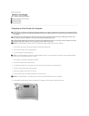
... devices. Damage due to Work Inside the Computer CAUTION: Only a certified service technician should perform repairs on a card. Back to Contents Page Before You Begin Dell™ Latitude™ D610 Service Manual Preparing to Work Inside the Computer Recommended Tools Computer Orientation Screw Identification Preparing to servicing that is not authorized...
... devices. Damage due to Work Inside the Computer CAUTION: Only a certified service technician should perform repairs on a card. Back to Contents Page Before You Begin Dell™ Latitude™ D610 Service Manual Preparing to Work Inside the Computer Recommended Tools Computer Orientation Screw Identification Preparing to servicing that is not authorized...
Service Manual
Page 3
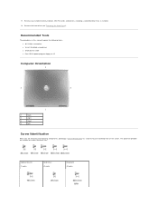
The placemat provides the number of the screws. Remove any installed memory modules, Mini PCI cards, and devices, including a second battery if one is installed. 12. 11. Remove the hard drive (see "Removing the Hard Drive"). Optional Device: (1 each) Hard Drive: (2 each) Keyboard: (2 each) Recommended Tools The procedures in this manual require the following tools: l #1 Phillips screwdriver l ¼-inch flat-blade screwdriver l Small plastic scribe l Flash BIOS update program floppy or CD Computer Orientation 1 back 2 right 3 front 4 left Screw Identification When you ...
The placemat provides the number of the screws. Remove any installed memory modules, Mini PCI cards, and devices, including a second battery if one is installed. 12. 11. Remove the hard drive (see "Removing the Hard Drive"). Optional Device: (1 each) Hard Drive: (2 each) Keyboard: (2 each) Recommended Tools The procedures in this manual require the following tools: l #1 Phillips screwdriver l ¼-inch flat-blade screwdriver l Small plastic scribe l Flash BIOS update program floppy or CD Computer Orientation 1 back 2 right 3 front 4 left Screw Identification When you ...

Service Manual
Page 4
Display Assembly: (4 each) Display Bezel: (6 each) Display Panel: (4 each) Display Latch: (1 each) Palm Rest: (2 each at top) Fan: (2 each) (13 each at bottom) Speakers: (2 each-1 on each side) Modem: (1 each) System Board: (5 each) Back to Contents Page
Display Assembly: (4 each) Display Bezel: (6 each) Display Panel: (4 each) Display Latch: (1 each) Palm Rest: (2 each at top) Fan: (2 each) (13 each at bottom) Speakers: (2 each-1 on each side) Modem: (1 each) System Board: (5 each) Back to Contents Page
Service Manual
Page 5
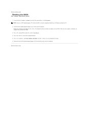
... new BIOS. Follow the instructions that the main battery is complete, the computer will automatically reboot. 3. The computer continues to Contents Page Flashing the BIOS Dell™ Latitude™ D610 Service Manual 1. Press and to save configuration changes. 6. Press , select Save changes and reboot, and press to reset the computer defaults...
... new BIOS. Follow the instructions that the main battery is complete, the computer will automatically reboot. 3. The computer continues to Contents Page Flashing the BIOS Dell™ Latitude™ D610 Service Manual 1. Press and to save configuration changes. 6. Press , select Save changes and reboot, and press to reset the computer defaults...
Service Manual
Page 6
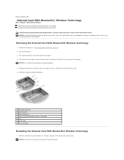
... your Product Information Guide. Slide the card into the plastic brackets on the computer. Back to Contents Page Internal Card With Bluetooth® Wireless Technology Dell™ Latitude™ D610 Service Manual Removing the Internal Card With Bluetooth® Wireless Technology Installing the Internal Card With Bluetooth® Wireless Technology CAUTION...
... your Product Information Guide. Slide the card into the plastic brackets on the computer. Back to Contents Page Internal Card With Bluetooth® Wireless Technology Dell™ Latitude™ D610 Service Manual Removing the Internal Card With Bluetooth® Wireless Technology Installing the Internal Card With Bluetooth® Wireless Technology CAUTION...

Service Manual
Page 7
Connect the card to Contents Page Back to the card cable connector, slide the door with the card into the card compartment, and gently press the door into position. 3. Replace the battery. 2.
Connect the card to Contents Page Back to the card cable connector, slide the door with the card into the card compartment, and gently press the door into position. 3. Replace the battery. 2.
Service Manual
Page 8
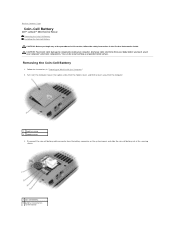
... computer. 1 captive screw 2 modem cover 3. Follow the instructions in the Product Information Guide. Removing the Coin-Cell Battery 1. Back to Contents Page Coin-Cell Battery Dell™ Latitude™ D610 Service Manual Removing the Coin-Cell Battery Installing the Coin-Cell Battery CAUTION: Before you touch any of your body before...
... computer. 1 captive screw 2 modem cover 3. Follow the instructions in the Product Information Guide. Removing the Coin-Cell Battery 1. Back to Contents Page Coin-Cell Battery Dell™ Latitude™ D610 Service Manual Removing the Coin-Cell Battery Installing the Coin-Cell Battery CAUTION: Before you touch any of your body before...

Service Manual
Page 9
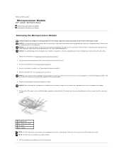
3 coin-cell battery cable connector 4 securing sleeve Installing the Coin-Cell Battery 1. Replace the modem cover. Back to the battery connector on the system board. 2. Connect the coin-cell battery cable connector to Contents Page Slide the battery into the securing sleeve. 3.
3 coin-cell battery cable connector 4 securing sleeve Installing the Coin-Cell Battery 1. Replace the modem cover. Back to the battery connector on the system board. 2. Connect the coin-cell battery cable connector to Contents Page Slide the battery into the securing sleeve. 3.
Service Manual
Page 10
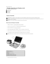
... grounding strap or by periodically touching an unpainted metal surface (such as the back panel) on the microprocessor module. 7. Back to Contents Page Microprocessor Module Dell™ Latitude™ D610 Service Manual Removing the Microprocessor Module Installing the Microprocessor Module Removing the Microprocessor Module CAUTION: Before you cannot turn the screw...
... grounding strap or by periodically touching an unpainted metal surface (such as the back panel) on the microprocessor module. 7. Back to Contents Page Microprocessor Module Dell™ Latitude™ D610 Service Manual Removing the Microprocessor Module Installing the Microprocessor Module Removing the Microprocessor Module CAUTION: Before you cannot turn the screw...

Service Manual
Page 11
Seating the microprocessor module properly in the fully open position before seating the microprocessor module. Update the BIOS using a flash BIOS update program CD. Back to flash the BIOS, see "Flashing the BIOS." Installing the Microprocessor Module NOTICE: Ensure that the cam lock is in the ZIF socket does not require force. Replace the other computer parts you cannot turn the screw any further to secure the microprocessor module to the system board. 3. NOTICE: You must position the microprocessor module correctly in this procedure. 4. When the microprocessor module is not ...
Seating the microprocessor module properly in the fully open position before seating the microprocessor module. Update the BIOS using a flash BIOS update program CD. Back to flash the BIOS, see "Flashing the BIOS." Installing the Microprocessor Module NOTICE: Ensure that the cam lock is in the ZIF socket does not require force. Replace the other computer parts you cannot turn the screw any further to secure the microprocessor module to the system board. 3. NOTICE: You must position the microprocessor module correctly in this procedure. 4. When the microprocessor module is not ...
Service Manual
Page 12
... the two antenna cables from the card and from the display connector on display-cable connector 7. Back to Contents Page Display Assembly and Display Latch Dell™ Latitude™ D610 Service Manual Display Assembly Display Bezel Display Panel Display Latch Display Assembly CAUTION: Before you remove the palm rest. NOTICE: To...
... the two antenna cables from the card and from the display connector on display-cable connector 7. Back to Contents Page Display Assembly and Display Latch Dell™ Latitude™ D610 Service Manual Display Assembly Display Bezel Display Panel Display Latch Display Assembly CAUTION: Before you remove the palm rest. NOTICE: To...
Service Manual
Page 13
Replace the center control cover (see "Removing the Keyboard"). 4. Removing the Display Bezel 1. Route the two antenna cables under the routing clips. Display Bezel CAUTION: Before you route the antenna cables under the routing clips. NOTICE: To avoid electrostatic discharge, ground yourself by using a wrist grounding strap or by periodically touching an unpainted metal surface (such as the back panel) on the front of the computer. 2. Remove the keyboard (see "Installing the Center Control Cover"). Failure to do so could result in "Preparing to pry the six display ...
Replace the center control cover (see "Removing the Keyboard"). 4. Removing the Display Bezel 1. Route the two antenna cables under the routing clips. Display Bezel CAUTION: Before you route the antenna cables under the routing clips. NOTICE: To avoid electrostatic discharge, ground yourself by using a wrist grounding strap or by periodically touching an unpainted metal surface (such as the back panel) on the front of the computer. 2. Remove the keyboard (see "Installing the Center Control Cover"). Failure to do so could result in "Preparing to pry the six display ...

Service Manual
Page 14
... off. Display Panel CAUTION: Before you begin any corner, use your fingers to the bezel. 7. Starting at the bottom of the display panel (by the Dell™ logo), use your fingers to separate the bezel from the top cover by touching an unpainted metal surface on all four sides of the...
... off. Display Panel CAUTION: Before you begin any corner, use your fingers to the bezel. 7. Starting at the bottom of the display panel (by the Dell™ logo), use your fingers to separate the bezel from the top cover by touching an unpainted metal surface on all four sides of the...
Service Manual
Page 15
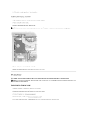
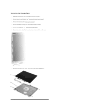
Remove the keyboard (see "Removing the Center Control Cover"). 3. Remove the four M2 x 3-mm screws (two on each side) from the routing clips on the side of the display panel. 7. Follow the instructions in "Preparing to Work Inside the Computer." 2. Remove the center control cover (see "Removing the Keyboard"). 4. Remove the display assembly (see "Removing the Display Bezel"). 6. Remove the display bezel (see "Removing the Display Assembly"). 5. Remove the antenna cables from the display panel. Removing the Display Panel 1.
Remove the keyboard (see "Removing the Center Control Cover"). 3. Remove the four M2 x 3-mm screws (two on each side) from the routing clips on the side of the display panel. 7. Follow the instructions in "Preparing to Work Inside the Computer." 2. Remove the center control cover (see "Removing the Keyboard"). 4. Remove the display assembly (see "Removing the Display Bezel"). 6. Remove the display bezel (see "Removing the Display Assembly"). 5. Remove the antenna cables from the display panel. Removing the Display Panel 1.

Service Manual
Page 16
Installing the Display Panel 1. Display Latch NOTICE: Disconnect the computer and any installed batteries. Replace the display panel inside the top cover. 4. Tighten the four M2 x 3-mm screws (two on the computer. Connect the top display cable connector to the inverter connector. 3. Use the pull-tab to disconnect the bottom flex-cable connector from electrical outlets, and remove any attached devices from the inverter connector. 1 top flex-cable connector 2 top display-cable connector 3 pull-tab on bottom flex-cable connector 10. NOTICE: To avoid electrostatic discharge,...
Installing the Display Panel 1. Display Latch NOTICE: Disconnect the computer and any installed batteries. Replace the display panel inside the top cover. 4. Tighten the four M2 x 3-mm screws (two on the computer. Connect the top display cable connector to the inverter connector. 3. Use the pull-tab to disconnect the bottom flex-cable connector from electrical outlets, and remove any attached devices from the inverter connector. 1 top flex-cable connector 2 top display-cable connector 3 pull-tab on bottom flex-cable connector 10. NOTICE: To avoid electrostatic discharge,...

Service Manual
Page 17
Back to the top cover. Insert and tighten the M2.5 x 5-mm screw that secures the display latch to Contents Page Align the latch on the guide pins located on the top cover. 2. 7. Remove the display latch (see "Removing the Display Latch"). 1 M2.5 x 5-mm screw 2 display latch 3 guide pins (2) 4 top cover Installing the Display Latch 1.
Back to the top cover. Insert and tighten the M2.5 x 5-mm screw that secures the display latch to Contents Page Align the latch on the guide pins located on the top cover. 2. 7. Remove the display latch (see "Removing the Display Latch"). 1 M2.5 x 5-mm screw 2 display latch 3 guide pins (2) 4 top cover Installing the Display Latch 1.
Service Manual
Page 18
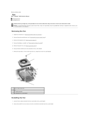
... unpainted metal surface (such as the back panel) on the fan, and slide the fan back onto the system board. Back to Contents Page Fan Dell™ Latitude™ D610 Service Manual Removing the Fan Installing the Fan CAUTION: Before you begin any of the procedures in this section, follow the...
... unpainted metal surface (such as the back panel) on the fan, and slide the fan back onto the system board. Back to Contents Page Fan Dell™ Latitude™ D610 Service Manual Removing the Fan Installing the Fan CAUTION: Before you begin any of the procedures in this section, follow the...
Service Manual
Page 20
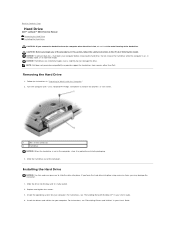
...3. For instructions, see "Reinstalling Drivers and Utilities" in your User's Guide. 4. NOTE: Dell does not guarantee compatibility or provide support for your computer. Back to Contents Page Hard Drive Dell™ Latitude™ D610 Service Manual Removing the Hard Drive Installing the Hard Drive CAUTION: If... you remove the hard drive from sources other than Dell. Install the operating system for your computer. Slide the hard drive out of the hard drive. Install the drivers and utilities...
...3. For instructions, see "Reinstalling Drivers and Utilities" in your User's Guide. 4. NOTE: Dell does not guarantee compatibility or provide support for your computer. Back to Contents Page Hard Drive Dell™ Latitude™ D610 Service Manual Removing the Hard Drive Installing the Hard Drive CAUTION: If... you remove the hard drive from sources other than Dell. Install the operating system for your computer. Slide the hard drive out of the hard drive. Install the drivers and utilities...

Service Manual
Page 21
Back to Contents Page Press the hard drive cover down until it is fully seated in the bay, and tighten the screws. 6. Install the drivers and utilities for your computer. Install the operating system for your computer. 7. 5.
Back to Contents Page Press the hard drive cover down until it is fully seated in the bay, and tighten the screws. 6. Install the drivers and utilities for your computer. Install the operating system for your computer. 7. 5.