Product Manual
Page 1
All rights reserved. Web/Installation Guide Product Model: TM DWS/DXS-3200 Series Layer 2+ Stackable Gigabit Ethernet Switches with optional XG uplinks Release 2.0 ©Copyright 2006.
All rights reserved. Web/Installation Guide Product Model: TM DWS/DXS-3200 Series Layer 2+ Stackable Gigabit Ethernet Switches with optional XG uplinks Release 2.0 ©Copyright 2006.
Product Manual
Page 2
Table of Contents Table of Contents DXS/DWS-3227/3227P, DXS/DWS-3250 User Guide Overview 7 Intended Audience...8 Device Description ...9 Viewing the Device ...9 DXS-3250/DWS Front Panel ...9 DXS/DWS-3227 Front Panel ...10 DXS/DWS-3227P Front Panel...10 Back Panels...11 Ports Description ...12 1000Base-T ......26 Installing the Device ...27 Desktop or Shelf Installation ...27 Rack Installation ...27 Connecting the Device ...30 Connecting the Switch to a Terminal ...30 AC Power Connection ...30 Initial Configuration ...31 General Configuration Information 31 Auto-Negotiation ...31 Device Port Default...
Table of Contents Table of Contents DXS/DWS-3227/3227P, DXS/DWS-3250 User Guide Overview 7 Intended Audience...8 Device Description ...9 Viewing the Device ...9 DXS-3250/DWS Front Panel ...9 DXS/DWS-3227 Front Panel ...10 DXS/DWS-3227P Front Panel...10 Back Panels...11 Ports Description ...12 1000Base-T ......26 Installing the Device ...27 Desktop or Shelf Installation ...27 Rack Installation ...27 Connecting the Device ...30 Connecting the Switch to a Terminal ...30 AC Power Connection ...30 Initial Configuration ...31 General Configuration Information 31 Auto-Negotiation ...31 Device Port Default...
Product Manual
Page 3
... Erase FLASH Sectors...47 Password Recovery ...48 WLAN Licence Key ...48 Getting Started...51 Starting the D-Link Embedded Web Interface 52 Understanding the D-Link Embedded Web Interface 54 Device Representation...55 Using the D-Link Embedded Web Interface Management Buttons 56 Using Screen and Table Options 57 Adding Configuration Information ...57 Modifying ... Stack Topology 72 Stacking Failover Topology...72 Stacking Members and Unit ID ...72 Removing and Replacing Stacking Members 73 Exchanging Stacking Members...74 Switching the Stacking Master ...74 Configuring Stacking ...75 Page 2
... Erase FLASH Sectors...47 Password Recovery ...48 WLAN Licence Key ...48 Getting Started...51 Starting the D-Link Embedded Web Interface 52 Understanding the D-Link Embedded Web Interface 54 Device Representation...55 Using the D-Link Embedded Web Interface Management Buttons 56 Using Screen and Table Options 57 Adding Configuration Information ...57 Modifying ... Stack Topology 72 Stacking Failover Topology...72 Stacking Members and Unit ID ...72 Removing and Replacing Stacking Members 73 Exchanging Stacking Members...74 Switching the Stacking Master ...74 Configuring Stacking ...75 Page 2
Product Manual
Page 10
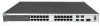
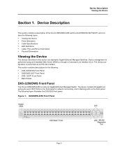
... panel for the following: • DXS-3250/DWS Front Panel • DXS/DWS-3227 Front Panel • DXS- 3227P Front Panel • Back Panels DXS-3250/DWS Front Panel The D-Link DXS/DWS-3250 is a 48 port Gigabit Ethernet Managed Switch. The device configuration is performed using an Embedded ...8226; Cable, Port, and Pinout Information • Physical Dimensions Viewing the Device The devices described in this section are stackable Gigabit Ethernet Managed Switches. Figure 1: DXS/DWS-3250 Front Panel Page 9 The device contains 48 gigabit network ports and 4 SFP Ports on the back panel.
... panel for the following: • DXS-3250/DWS Front Panel • DXS/DWS-3227 Front Panel • DXS- 3227P Front Panel • Back Panels DXS-3250/DWS Front Panel The D-Link DXS/DWS-3250 is a 48 port Gigabit Ethernet Managed Switch. The device configuration is performed using an Embedded ...8226; Cable, Port, and Pinout Information • Physical Dimensions Viewing the Device The devices described in this section are stackable Gigabit Ethernet Managed Switches. Figure 1: DXS/DWS-3250 Front Panel Page 9 The device contains 48 gigabit network ports and 4 SFP Ports on the back panel.
Product Manual
Page 11
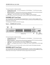
...follows: • 24 Gigabit Ethernet ports - The RJ-45 ports are desig- The following figure illustrates the DXS-3227 front panel: Figure 2: DXS/DWS-3227 Front Panel The device front panel is configured as 10/100/1000Base-T . On the front panel there are four ...designated as follows: • 48 Gigabit Ethernet ports - DXS/DWS-3227P Front Panel The D-Link DXS-3227P is a 24 port Gigabit Ethernet Managed Switch. DXS/DWS-3227 Front Panel The D-Link DXS-3227 is a 24 port Gigabit Ethernet Managed Switch. cations. Hot-swappable optical interface for network connectivity, and 2 ...
...follows: • 24 Gigabit Ethernet ports - The RJ-45 ports are desig- The following figure illustrates the DXS-3227 front panel: Figure 2: DXS/DWS-3227 Front Panel The device front panel is configured as 10/100/1000Base-T . On the front panel there are four ...designated as follows: • 48 Gigabit Ethernet ports - DXS/DWS-3227P Front Panel The D-Link DXS-3227P is a 24 port Gigabit Ethernet Managed Switch. DXS/DWS-3227 Front Panel The D-Link DXS-3227 is a 24 port Gigabit Ethernet Managed Switch. cations. Hot-swappable optical interface for network connectivity, and 2 ...
Product Manual
Page 21
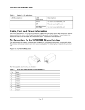
...Base-TX Pin Use 1 TxRx 1+ 2 TxRx 1- 3 TxRx 2+ 4 TxRx 2- 5 TxRx 3+ 6 TxRx 3- 7 TxRx 4+ 8 TxRx 4- DXS/DWS 3200 Series User Guide Table 4: System's LED Indications LED Description LED Indication Amber Off alternating Green and Amber Description An error is occurred at this ... cables. The following table describes the pin allocation: Table 5: RJ-45 Pin Connections for the 10/100/1000 Ethernet Interface The switching port can connect to stations wired in standard RJ-45 Ethernet station mode using straight cables. Transmission devices connected to the device ports...
...Base-TX Pin Use 1 TxRx 1+ 2 TxRx 1- 3 TxRx 2+ 4 TxRx 2- 5 TxRx 3+ 6 TxRx 3- 7 TxRx 4+ 8 TxRx 4- DXS/DWS 3200 Series User Guide Table 4: System's LED Indications LED Description LED Indication Amber Off alternating Green and Amber Description An error is occurred at this ... cables. The following table describes the pin allocation: Table 5: RJ-45 Pin Connections for the 10/100/1000 Ethernet Interface The switching port can connect to stations wired in standard RJ-45 Ethernet station mode using straight cables. Transmission devices connected to the device ports...
Product Manual
Page 26
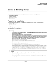
... exceed 40ºC (104ºF). To determine the possibility of overloading the supply circuits, add together the ampere ratings of the switch is not exposed to prevent it may cause electrical shock. Mounting Device This section contains information for installing the device, and includes ...plug is not damaged. • Ensure the product is not exposed to cool before removing covers or touching internal equipment. • Ensure the switch does not overload the power circuits, wiring, and over . • Ensure the power source circuits are properly grounded. • Observe and ...
... exceed 40ºC (104ºF). To determine the possibility of overloading the supply circuits, add together the ampere ratings of the switch is not exposed to prevent it may cause electrical shock. Mounting Device This section contains information for installing the device, and includes ...plug is not damaged. • Ensure the product is not exposed to cool before removing covers or touching internal equipment. • Ensure the switch does not overload the power circuits, wiring, and over . • Ensure the power source circuits are properly grounded. • Observe and ...
Product Manual
Page 28
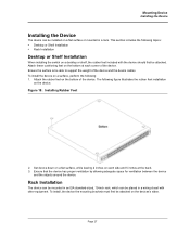
... the rubber feet installation on a surface, perform the following topics: • Desktop or Shelf Installation • Rack Installation Desktop or Shelf Installation When installing the switch on the bottom at each side and 5 inches at the back. 3. Attach the rubber feet on each corner of the device. Attach these cushioning feet...
... the rubber feet installation on a surface, perform the following topics: • Desktop or Shelf Installation • Rack Installation Desktop or Shelf Installation When installing the switch on the bottom at each side and 5 inches at the back. 3. Attach the rubber feet on each corner of the device. Attach these cushioning feet...
Product Manual
Page 31
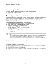
... the appropriate port to connect to the device. Go to www.microsoft.com for monitoring and configuring the device. DXS/DWS 3200 Series User Guide Connecting the Device This section describes how to connect the device, and includes the following sections: • ...Connecting the Switch to a Terminal • AC Power Connection Connecting the Switch to a Terminal The device is connected to a terminal through an console port on the front panel, which enables...
... the appropriate port to connect to the device. Go to www.microsoft.com for monitoring and configuring the device. DXS/DWS 3200 Series User Guide Connecting the Device This section describes how to connect the device, and includes the following sections: • ...Connecting the Switch to a Terminal • AC Power Connection Connecting the Switch to a Terminal The device is connected to a terminal through an console port on the front panel, which enables...
Product Manual
Page 32
... configuration, the standard device configuration is described later in the following topics: • General Configuration Information • Booting the Switch • Configuration Overview • Advanced Configuration • Software Download and Reboot • Configuring Stacking • Startup Menu ...Functions After completing all external connections, connect a terminal to the device to -point link segment. Performing other procedures. This automatically configures both devices to take maximum advantage of their abilities • Acknowledge ...
... configuration, the standard device configuration is described later in the following topics: • General Configuration Information • Booting the Switch • Configuration Overview • Advanced Configuration • Software Download and Reboot • Configuring Stacking • Startup Menu ...Functions After completing all external connections, connect a terminal to the device to -point link segment. Performing other procedures. This automatically configures both devices to take maximum advantage of their abilities • Acknowledge ...
Product Manual
Page 33
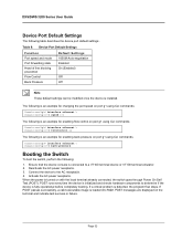
... through Power On Self Test (POST). Page 32 Console(config)# interface ethernet 1 Console(config-if)# back-pressure Booting the Switch To boot the switch, perform the following table describes the device port default settings:. Deactivate the AC power receptacle. 3. POST runs every time the device is turned on the ... example for enabling flow control on port g1 using CLI commands: Console(config)# interface ethernet 1 Console(config-if)# flowcontrol on The following is installed. DXS/DWS 3200 Series User Guide Device Port Default Settings The following : 1.
... through Power On Self Test (POST). Page 32 Console(config)# interface ethernet 1 Console(config-if)# back-pressure Booting the Switch To boot the switch, perform the following table describes the device port default settings:. Deactivate the AC power receptacle. 3. POST runs every time the device is turned on the ... example for enabling flow control on port g1 using CLI commands: Console(config)# interface ethernet 1 Console(config-if)# flowcontrol on The following is installed. DXS/DWS 3200 Series User Guide Device Port Default Settings The following : 1.
Product Manual
Page 34
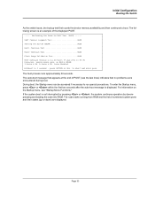
... that appears at the end of POST (see "Startup Menu Functions." Page 33 Autoboot in 2 seconds - to run special procedures. Initial Configuration Booting the Switch As the switch boots, the bootup test first counts the device memory availability and then continues to boot. Performing the Power-On Self Test (POST) -----UART Channel...
... that appears at the end of POST (see "Startup Menu Functions." Page 33 Autoboot in 2 seconds - to run special procedures. Initial Configuration Booting the Switch As the switch boots, the bootup test first counts the device memory availability and then continues to boot. Performing the Power-On Self Test (POST) -----UART Channel...
Product Manual
Page 35
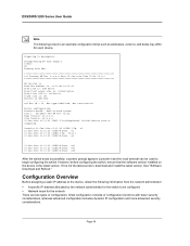
...is: 47104K bytes Dram first PTR is: 0x1200000 Flash size is not the latest version, download and install the latest version. Running SW Ver. DXS/DWS 3200 Series User Guide Note The following information from RAM... DB-DX240-24G HW Rev. See "Software Download and Reboot." Preparing to -back system ...: e2 01-Jan-200x 01:01:23 %LINK-I-Up: Vlan 1 01-Jan-200x 01:01:23 %LINK-W-Down: e4 . . . 01-Jan-200x 01:01:23 %LINK-W-Down: e46 01-Jan-200x 01:01:23 %LINK-W-Down: e47 01-Jan-200x 01:01:23 %LINK-W-Down: e48 After the switch boots successfully, a system prompt appears (console>) ...
...is: 47104K bytes Dram first PTR is: 0x1200000 Flash size is not the latest version, download and install the latest version. Running SW Ver. DXS/DWS 3200 Series User Guide Note The following information from RAM... DB-DX240-24G HW Rev. See "Software Download and Reboot." Preparing to -back system ...: e2 01-Jan-200x 01:01:23 %LINK-I-Up: Vlan 1 01-Jan-200x 01:01:23 %LINK-W-Down: e4 . . . 01-Jan-200x 01:01:23 %LINK-W-Down: e46 01-Jan-200x 01:01:23 %LINK-W-Down: e47 01-Jan-200x 01:01:23 %LINK-W-Down: e48 After the switch boots successfully, a system prompt appears (console>) ...
Product Manual
Page 36
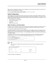
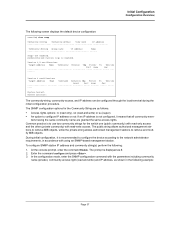
... Directed Broadcast disable The above example is the IP address of the next hop that can be used to allow remote management. To manage the switch from a remote network, a static route must be changed from an SNMP-based management station, SNMP community strings must belong to router. To use the ip... on each port of the device IP interfaces. To save the configuration, enter the following configurations are port specific. The commands to be managed from switch to the same subnet as shown in the device tables.
... Directed Broadcast disable The above example is the IP address of the next hop that can be used to allow remote management. To manage the switch from a remote network, a static route must be changed from an SNMP-based management station, SNMP community strings must belong to router. To use the ip... on each port of the device IP interfaces. To save the configuration, enter the following configurations are port specific. The commands to be managed from switch to the same subnet as shown in the device tables.
Product Manual
Page 37
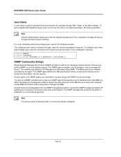
...username admin password lee privilege 15 SNMP Community Strings Simple Network Management Protocol (SNMP) provides a method for managing network devices. Note The device switch is delivered with the highest privilege level (15) is allowed to manage the device through SSH, Telnet, or the Web interface. For more ... from any SNMP management platform, except the SNMP management station IP address and community (community name and access rights). DXS/DWS 3200 Series User Guide User Name A user name is used to manage the device remotely, for example through the Web browser interface.
...username admin password lee privilege 15 SNMP Community Strings Simple Network Management Protocol (SNMP) provides a method for managing network devices. Note The device switch is delivered with the highest privilege level (15) is allowed to manage the device through SSH, Telnet, or the Web interface. For more ... from any SNMP management platform, except the SNMP management station IP address and community (community name and access rights). DXS/DWS 3200 Series User Guide User Name A user name is used to manage the device remotely, for example through the Web browser interface.
Product Manual
Page 38
...: ro (read only), rw (read -only access and the other (private community) with using an SNMP-based management station. The SNMP configuration options for the switch one (public community) with read -and-write) or su (super). • An option to configure IP address or not: If an IP address is recommended...
...: ro (read only), rw (read -only access and the other (private community) with using an SNMP-based management station. The SNMP configuration options for the switch one (public community) with read -and-write) or su (super). • An option to configure IP address or not: If an IP address is recommended...
Product Manual
Page 40
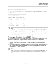
...this case, the device acts as a BOOTP client. Receiving an IP Address From a BOOTP Server The standard BOOTP protocol is supported and enables the switch to delete the startup configuration from any port to a BOOTP server or subnet containing such a server, to one with no configuration and in the... cancels the BOOTP process before completion and the device does not receive an IP address from a BOOTP server: 1. In this instance, the switch retrieves the new configuration file and boots from it to reload the same file again. Select and connect any standard BOOTP server in the new...
...this case, the device acts as a BOOTP client. Receiving an IP Address From a BOOTP Server The standard BOOTP protocol is supported and enables the switch to delete the startup configuration from any port to a BOOTP server or subnet containing such a server, to one with no configuration and in the... cancels the BOOTP process before completion and the device does not receive an IP address from a BOOTP server: 1. In this instance, the switch retrieves the new configuration file and boots from it to reload the same file again. Select and connect any standard BOOTP server in the new...
Product Manual
Page 43
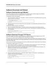
...saved on the Flash Image-1 active (selected for downloading device software (system and boot images) through a TFTP server. On the next boot, the switch decompresses and runs the currently active system image unless chosen otherwise. Ensure that appears: Console# copy xmodem:image Please download program using XModem, which is...images) using XMODEM console# Software Download Through TFTP Server This section contains instructions for next boot)Image-2 not active Console# Page 42 DXS/DWS 3200 Series User Guide Software Download and Reboot Software Download through the TFTP server: 1.
...saved on the Flash Image-1 active (selected for downloading device software (system and boot images) through a TFTP server. On the next boot, the switch decompresses and runs the currently active system image unless chosen otherwise. Ensure that appears: Console# copy xmodem:image Please download program using XModem, which is...images) using XMODEM console# Software Download Through TFTP Server This section contains instructions for next boot)Image-2 not active Console# Page 42 DXS/DWS 3200 Series User Guide Software Download and Reboot Software Download through the TFTP server: 1.
Product Manual
Page 44
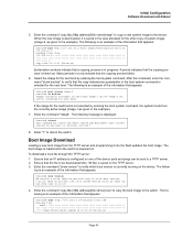
...mm:ss] Exclamation symbols indicate that a copying process is powered on. Enter the command "reload". The boot image is loaded when the switch is in the boot system command is selected for the next boot is currently running on the Flash Image-1 active Image-2 not active (selected...an example of the information that appears: Console# boot system image-2 Console# sh bootvar Images currently available on the device. Enter "Y" to the switch. ing is saved in the example). 7. When the new image is downloaded, it into the flash updates the boot image. The following message...
...mm:ss] Exclamation symbols indicate that a copying process is powered on. Enter the command "reload". The boot image is loaded when the switch is in the boot system command is selected for the next boot is currently running on the Flash Image-1 active Image-2 not active (selected...an example of the information that appears: Console# boot system image-2 Console# sh bootvar Images currently available on the device. Enter "Y" to the switch. ing is saved in the example). 7. When the new image is downloaded, it into the flash updates the boot image. The following message...
Product Manual
Page 45
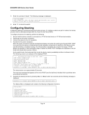
... through POST. to reboot the switch. The auto-boot message that appears at the end of POST (see the last lines) indicates that the device console is fully operational before completely booting. The Startup Menu is performed during boot. 5. DXS/DWS 3200 Series User Guide 5. Configuring Stacking... device to boot. If POST passes successfully, a valid executable image is turned on the terminal and indicate test success or failure. As the switch boots, the bootup test first counts the device memory availability and then continues to the AC receptacle. 4. Do you want to exit: Page ...
... through POST. to reboot the switch. The auto-boot message that appears at the end of POST (see the last lines) indicates that the device console is fully operational before completely booting. The Startup Menu is performed during boot. 5. DXS/DWS 3200 Series User Guide 5. Configuring Stacking... device to boot. If POST passes successfully, a valid executable image is turned on the terminal and indicate test success or failure. As the switch boots, the bootup test first counts the device memory availability and then continues to the AC receptacle. 4. Do you want to exit: Page ...

