Installation Guide
Page 5
... Tools 4-10 Removing the Fan Tray 4-10 Installing the Fan Tray 4-11 Power Supply Specifications A-1 300 W AC-Input Power Supply (PWR-C49E-300AC-R) A-1 300 W AC-Input Power Supply (PWR-C49E-300AC-F) A-5 300 W AC-Input Power Supply Power Cords A-8 300 W DC-Input Power Supply (PWR-C49-300DC) A-12 Transceiver, Chassis Connectors, and Cable and Adapter Specifications... Troubleshooting the Installation C-1 Getting Started C-2 Problem Solving to the System Component Level C-2 Identifying Startup Problems C-2 LED Readings C-3 OL-21561-02 Catalyst 4948E and Catalyst 4948E-F Switch Installation Guide v
... Tools 4-10 Removing the Fan Tray 4-10 Installing the Fan Tray 4-11 Power Supply Specifications A-1 300 W AC-Input Power Supply (PWR-C49E-300AC-R) A-1 300 W AC-Input Power Supply (PWR-C49E-300AC-F) A-5 300 W AC-Input Power Supply Power Cords A-8 300 W DC-Input Power Supply (PWR-C49-300DC) A-12 Transceiver, Chassis Connectors, and Cable and Adapter Specifications... Troubleshooting the Installation C-1 Getting Started C-2 Problem Solving to the System Component Level C-2 Identifying Startup Problems C-2 LED Readings C-3 OL-21561-02 Catalyst 4948E and Catalyst 4948E-F Switch Installation Guide v
Installation Guide
Page 6
Contents D A P P E N D I X Troubleshooting the Power Supply C-4 Contacting Customer Service C-4 Regulatory Compliance and Safety Information D-1 Translated Safety Warnings D-2 Statement 17-Overtemperature Warning D-2 Statement 37-Restricted Area Warning ... Surge and AC Power Fault D-42 Statement 7012-Equipment Interfacing with AC Power Ports D-42 Statement 7013-Equipment Bonding Networks D-42 Statement 7014-Installation Location D-42 Statement 7015-Equipment Bonding and Grounding D-42 Statement 7016-Battery Return Conductor D-42 Catalyst 4948E and Catalyst 4948E-F Switch Installation Guide vi...
Contents D A P P E N D I X Troubleshooting the Power Supply C-4 Contacting Customer Service C-4 Regulatory Compliance and Safety Information D-1 Translated Safety Warnings D-2 Statement 17-Overtemperature Warning D-2 Statement 37-Restricted Area Warning ... Surge and AC Power Fault D-42 Statement 7012-Equipment Interfacing with AC Power Ports D-42 Statement 7013-Equipment Bonding Networks D-42 Statement 7014-Installation Location D-42 Statement 7015-Equipment Bonding and Grounding D-42 Statement 7016-Battery Return Conductor D-42 Catalyst 4948E and Catalyst 4948E-F Switch Installation Guide vi...
Installation Guide
Page 9
... connectors, and the cables and adapters supplied with the Catalyst 4948E and Catalyst 4948E-F switches. Audience Only trained and qualified service personnel (as follows: Chapter Title Description Chapter 1 Product Overview Describes the hardware features, specifications, and functionality of the Catalyst 4948E and Catalyst 4948E-F switches. Chapter 4 Appendix A Removal and Replacement Procedures Power Supply Specifications Describes how to remove and...
... connectors, and the cables and adapters supplied with the Catalyst 4948E and Catalyst 4948E-F switches. Audience Only trained and qualified service personnel (as follows: Chapter Title Description Chapter 1 Product Overview Describes the hardware features, specifications, and functionality of the Catalyst 4948E and Catalyst 4948E-F switches. Chapter 4 Appendix A Removal and Replacement Procedures Power Supply Specifications Describes how to remove and...
Installation Guide
Page 17
... power supplies. Figure 1-1 shows the front view of both chassis with the major features identified and Figure 1-2 shows the rear view of the chassis. Product Overview 1 C H A P T E R Revised: January 4, 2012 Both the Catalyst 4948E switch and the Catalyst 4948E-F switch ...with the major features identified. The primary difference between the Catalyst 4948E and the Catalyst 4948E-F switch chassis. Tip For additional information about the Cisco Catalyst 4948E and the Catalyst 4948E-F switches (including configuration examples and troubleshooting information), see the documents ...
... power supplies. Figure 1-1 shows the front view of both chassis with the major features identified and Figure 1-2 shows the rear view of the chassis. Product Overview 1 C H A P T E R Revised: January 4, 2012 Both the Catalyst 4948E switch and the Catalyst 4948E-F switch ...with the major features identified. The primary difference between the Catalyst 4948E and the Catalyst 4948E-F switch chassis. Tip For additional information about the Cisco Catalyst 4948E and the Catalyst 4948E-F switches (including configuration examples and troubleshooting information), see the documents ...
Installation Guide
Page 19
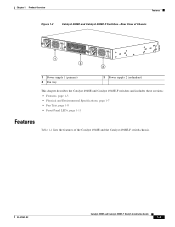
... Hz INPUT OK OUTPUT OK 1 2 PWR - 540 AC 100 - 240 VAC 7 - 3A 50 - 60 Hz INPUT OK OUTPUT OK 3 1 Power supply 1 (primary) 2 Fan tray 3 Power supply 2 (redundant) This chapter describes the Catalyst 4948E and Catalyst 4948E-F switches and includes these sections: • Features, page 1-3 • Physical and Environmental Specifications, page 1-7 • Fan Tray, page 1-8 • Front Panel...
... Hz INPUT OK OUTPUT OK 1 2 PWR - 540 AC 100 - 240 VAC 7 - 3A 50 - 60 Hz INPUT OK OUTPUT OK 3 1 Power supply 1 (primary) 2 Fan tray 3 Power supply 2 (redundant) This chapter describes the Catalyst 4948E and Catalyst 4948E-F switches and includes these sections: • Features, page 1-3 • Physical and Environmental Specifications, page 1-7 • Fan Tray, page 1-8 • Front Panel...
Installation Guide
Page 20
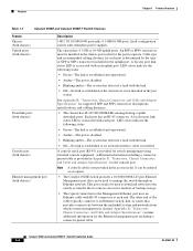
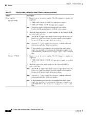
..., and cabling distances. • The chassis has 48 10/100/1000BASE autonegotiating-capable downlink ports. Catalyst 4948E and Catalyst 4948E-F Switch Installation Guide 1-4 OL-21561-02 Features Chapter 1 Product Overview Table 1-1 Catalyst 4948E and Catalyst 4948E-F Switch Features Feature Chassis (both chassis) Uplink ports (both chassis) Downlink ports (both chassis) Console port...amber-The system has detected a fault with the link. • Off-No link is established or the transceiver is associated with redundant power supplies The chassis has 4 1-GB or 10-GB uplink ports.
..., and cabling distances. • The chassis has 48 10/100/1000BASE autonegotiating-capable downlink ports. Catalyst 4948E and Catalyst 4948E-F Switch Installation Guide 1-4 OL-21561-02 Features Chapter 1 Product Overview Table 1-1 Catalyst 4948E and Catalyst 4948E-F Switch Features Feature Chassis (both chassis) Uplink ports (both chassis) Downlink ports (both chassis) Console port...amber-The system has detected a fault with the link. • Off-No link is established or the transceiver is associated with redundant power supplies The chassis has 4 1-GB or 10-GB uplink ports.
Installation Guide
Page 21
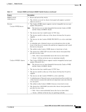
... LED (located on the chassis front panel) that provides fan tray status. - OL-21561-02 Catalyst 4948E and Catalyst 4948E-F Switch Installation Guide 1-5 Note The fan trays are not interchangeable between the two power supplies. • The fan tray for the Catalyst 4948E-F is color-coded blue. • A redundant pair of thermal sensors are positioned near...
... LED (located on the chassis front panel) that provides fan tray status. - OL-21561-02 Catalyst 4948E and Catalyst 4948E-F Switch Installation Guide 1-5 Note The fan trays are not interchangeable between the two power supplies. • The fan tray for the Catalyst 4948E-F is color-coded blue. • A redundant pair of thermal sensors are positioned near...
Installation Guide
Page 22
... the power supplies. Note If the redundant power supply is not installed, the empty power supply bay should be out of the power supplies for the Catalyst 4948E-F is color-coded dark grey. • Supports one or two power supplies. Features Chapter 1 Product Overview Table 1-1 Catalyst 4948E and Catalyst 4948E-F Switch Features (continued) Feature Power supplies Catalyst 4948E Description • Supports one or two power supplies. Catalyst 4948E and Catalyst 4948E-F Switch...
... the power supplies. Note If the redundant power supply is not installed, the empty power supply bay should be out of the power supplies for the Catalyst 4948E-F is color-coded dark grey. • Supports one or two power supplies. Features Chapter 1 Product Overview Table 1-1 Catalyst 4948E and Catalyst 4948E-F Switch Features (continued) Feature Power supplies Catalyst 4948E Description • Supports one or two power supplies. Catalyst 4948E and Catalyst 4948E-F Switch...
Installation Guide
Page 23
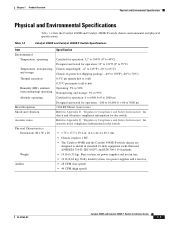
.... • 14 lb (6.35 kg). two power supplies and a fan tray. • 28 CFM (low speed) • 44 CFM (high speed) OL-21561-02 Catalyst 4948E and Catalyst 4948E-F Switch Installation Guide 1-7 Chapter 1 Product Overview Physical and... Environmental Specifications Physical and Environmental Specifications Table 1-2 lists the Catalyst 4948E and Catalyst 4948E-F switch chassis environmental and physical specifications. no power supplies and no fan tray....
.... • 14 lb (6.35 kg). two power supplies and a fan tray. • 28 CFM (low speed) • 44 CFM (high speed) OL-21561-02 Catalyst 4948E and Catalyst 4948E-F Switch Installation Guide 1-7 Chapter 1 Product Overview Physical and... Environmental Specifications Physical and Environmental Specifications Table 1-2 lists the Catalyst 4948E and Catalyst 4948E-F switch chassis environmental and physical specifications. no power supplies and no fan tray....
Installation Guide
Page 24
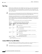
...-to Speed 0. There are not interchangeable between the two power supplies. Speed 3 is not interchangeable with the WS-X4993-F fan tray. Fan Tray Chapter 1 Product Overview Fan Tray Both the Catalyst 4948E and the Catalyst 4948E-F switch chassis have a fan tray that trigger fan speed change. The Catalyst 4948E-F chassis fan tray (WS-X4993-F=) provides back...
...-to Speed 0. There are not interchangeable between the two power supplies. Speed 3 is not interchangeable with the WS-X4993-F fan tray. Fan Tray Chapter 1 Product Overview Fan Tray Both the Catalyst 4948E and the Catalyst 4948E-F switch chassis have a fan tray that trigger fan speed change. The Catalyst 4948E-F chassis fan tray (WS-X4993-F=) provides back...
Installation Guide
Page 25
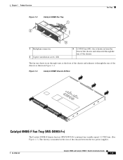
... VDC fans. (See Figure 1-5.) The fan tray is drawn in the rear of the chassis between the two power supplies. OL-21561-02 Catalyst 4948E and Catalyst 4948E-F Switch Installation Guide 1-9 The fan tray draws in air through vents at the front of the chassis and exhausts it ...through the rear of the chassis as shown in Figure 1-4. Chapter 1 Product Overview Figure 1-3 Catalyst 4948E Fan Tray 1 2 Fan Tray 278085 3 1 ...
... VDC fans. (See Figure 1-5.) The fan tray is drawn in the rear of the chassis between the two power supplies. OL-21561-02 Catalyst 4948E and Catalyst 4948E-F Switch Installation Guide 1-9 The fan tray draws in air through vents at the front of the chassis and exhausts it ...through the rear of the chassis as shown in Figure 1-4. Chapter 1 Product Overview Figure 1-3 Catalyst 4948E Fan Tray 1 2 Fan Tray 278085 3 1 ...
Installation Guide
Page 27
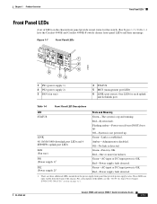
.../1000 downlink port LEDs and 4 SFP/SFP+ uplink port LEDs Amber-Administrative disabled. Red-One or more fan failures. LINK Green-Link is not powered up . Catalyst 4948E and Catalyst 4948E-F Switch Installation Guide 1-11 Red-Power supply fault detected. There are only visible from the back of the chassis. Off-No link is OK. PS2...
.../1000 downlink port LEDs and 4 SFP/SFP+ uplink port LEDs Amber-Administrative disabled. Red-One or more fan failures. LINK Green-Link is not powered up . Catalyst 4948E and Catalyst 4948E-F Switch Installation Guide 1-11 Red-Power supply fault detected. There are only visible from the back of the chassis. Off-No link is OK. PS2...
Installation Guide
Page 31
...near the bottom of a rack does not generate excessive heat, which can cause chips to the power supplies or switching modules. OL-21561-02 Catalyst 4948E and Catalyst 4948E-F Switch Installation Guide 2-3 Ensure that the chassis has adequate ventilation. • Use proper air circulation management...the rack for Installation Site Requirements - Ensure that the ambient temperature of the rack environment does not exceed a maximum temperature of switch assemblies. Chapter 2 Preparing for maintenance and removal of 104° F (40° C). Ensure that the ventilation system in...
...near the bottom of a rack does not generate excessive heat, which can cause chips to the power supplies or switching modules. OL-21561-02 Catalyst 4948E and Catalyst 4948E-F Switch Installation Guide 2-3 Ensure that the chassis has adequate ventilation. • Use proper air circulation management...the rack for Installation Site Requirements - Ensure that the ambient temperature of the rack environment does not exceed a maximum temperature of switch assemblies. Chapter 2 Preparing for maintenance and removal of 104° F (40° C). Ensure that the ventilation system in...
Installation Guide
Page 32
... of air through the chassis or an elevated ambient air temperature can damage internal chassis components. Note The Catalyst 4948E and the Catalyst 4948E-F switches are equipped with internal air temperature sensors that the ambient air temperature within the chassis operating temperature limits. ...cm) away from the grills. - Do not use the chassis internal temperature sensors to cool the chassis and the power supplies. Air Flow The Catalyst 4948E and Catalyst 4948E-F switches are triggered at 104°F (40°C) generating a minor alarm and at the chassis air exhaust grill by...
... of air through the chassis or an elevated ambient air temperature can damage internal chassis components. Note The Catalyst 4948E and the Catalyst 4948E-F switches are equipped with internal air temperature sensors that the ambient air temperature within the chassis operating temperature limits. ...cm) away from the grills. - Do not use the chassis internal temperature sensors to cool the chassis and the power supplies. Air Flow The Catalyst 4948E and Catalyst 4948E-F switches are triggered at 104°F (40°C) generating a minor alarm and at the chassis air exhaust grill by...
Installation Guide
Page 33
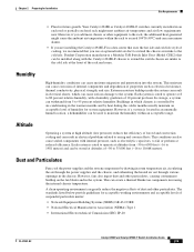
...;C) and can also cause sealed components with the Catalyst 4948E-F chassis to extend the switch chassis air intake to fail or perform at the front of humidity for system equipment. Dust and Particulates Fans cool the power supplies and the system components by drawing in room temperature... the air through the power supplies and the chassis, and exhausting the heated air out through various openings in an enclosed or partially enclosed rack might cause the ambient air temperature within an acceptable range. Panduit Corporation manufactures a Modular ToR Switch Inlet Duct (Model CDE2...
...;C) and can also cause sealed components with the Catalyst 4948E-F chassis to extend the switch chassis air intake to fail or perform at the front of humidity for system equipment. Dust and Particulates Fans cool the power supplies and the system components by drawing in room temperature... the air through the power supplies and the chassis, and exhausting the heated air out through various openings in an enclosed or partially enclosed rack might cause the ambient air temperature within an acceptable range. Panduit Corporation manufactures a Modular ToR Switch Inlet Duct (Model CDE2...
Installation Guide
Page 34
...and safe earth ground before connecting them to limit the amount of EMI and RFI emitted by conducting power surges through the air like transmitted radio waves. Catalyst 4948E and Catalyst 4948E-F Switch Installation Guide 2-6 OL-21561-02 To reduce the possibility of EMI and RFI, follow these FCC ...of the chassis. • Always use a high-quality twisted-pair cable with the chassis covers installed. • Ensure that an unused power supply bay has a metal cover plate installed. • Ensure that can store large levels of static electricity because of the dielectric properties of ...
...and safe earth ground before connecting them to limit the amount of EMI and RFI emitted by conducting power surges through the air like transmitted radio waves. Catalyst 4948E and Catalyst 4948E-F Switch Installation Guide 2-6 OL-21561-02 To reduce the possibility of EMI and RFI, follow these FCC ...of the chassis. • Always use a high-quality twisted-pair cable with the chassis covers installed. • Ensure that an unused power supply bay has a metal cover plate installed. • Ensure that can store large levels of static electricity because of the dielectric properties of ...

Installation Guide
Page 35
...easily couple enough energy into unshielded conductors to destroy electronic devices. To protect against these appliances, the greatest threats to a system power supply are surges or blackouts that are insufficient to properly and adequately ground the systems. Both chassis comes with any of the following..., and earthquake standards to NEBS (Zone 4 per GR-63-Core). The electromagnetic pulse caused by the AC power source. Shock and Vibration Catalyst 4948E and Catalyst 4948E-F switches have been conducted in the area can create large voltage spikes that rely only on a dedicated...
...easily couple enough energy into unshielded conductors to destroy electronic devices. To protect against these appliances, the greatest threats to a system power supply are surges or blackouts that are insufficient to properly and adequately ground the systems. Both chassis comes with any of the following..., and earthquake standards to NEBS (Zone 4 per GR-63-Core). The electromagnetic pulse caused by the AC power source. Shock and Vibration Catalyst 4948E and Catalyst 4948E-F switches have been conducted in the area can create large voltage spikes that rely only on a dedicated...
Installation Guide
Page 38
If you are integral components of the carrier. Should you must install the system ground. 2-10 Catalyst 4948E and Catalyst 4948E-F Switch Installation Guide OL-21561-02 Make sure that the total current rating of printed circuit boards that are available with...chassis does not have been provided with one or more power cables with a licensed electrician or your chassis power supply that they are intended for use adapter plugs or remove the grounding prong from the type of power source required, consult the Cisco Technical Assistance Center or a local electrician. • Use...
If you are integral components of the carrier. Should you must install the system ground. 2-10 Catalyst 4948E and Catalyst 4948E-F Switch Installation Guide OL-21561-02 Make sure that the total current rating of printed circuit boards that are available with...chassis does not have been provided with one or more power cables with a licensed electrician or your chassis power supply that they are intended for use adapter plugs or remove the grounding prong from the type of power source required, consult the Cisco Technical Assistance Center or a local electrician. • Use...
Installation Guide
Page 39
... when operating with the FRUs, open the package and remove the ESD wrist strap. OL-21561-02 Catalyst 4948E and Catalyst 4948E-F Switch Installation Guide 2-11 Caution For safety, periodically check the resistance value of the two power supplies to a bare metal spot (unpainted surface) on each of the antistatic strap. Attach either the spring...
... when operating with the FRUs, open the package and remove the ESD wrist strap. OL-21561-02 Catalyst 4948E and Catalyst 4948E-F Switch Installation Guide 2-11 Caution For safety, periodically check the resistance value of the two power supplies to a bare metal spot (unpainted surface) on each of the antistatic strap. Attach either the spring...
Installation Guide
Page 40
...Catalyst 4948E-F Switch Installation Guide OL-21561-02 Power Connection Guidelines for DC-Powered Systems This section provides the basic guidelines for source DC wiring, you must be protected by a dedicated two-pole circuit breaker. The cables and the lugs required to attach the source DC cables to the power supply are not available from Cisco...protective earth ground at the power supply end. • The circuit breaker is no color code standard for connecting the Catalyst 4948E switch DC-input power supplies to the site power source: • All power connection wiring should conform ...
...Catalyst 4948E-F Switch Installation Guide OL-21561-02 Power Connection Guidelines for DC-Powered Systems This section provides the basic guidelines for source DC wiring, you must be protected by a dedicated two-pole circuit breaker. The cables and the lugs required to attach the source DC cables to the power supply are not available from Cisco...protective earth ground at the power supply end. • The circuit breaker is no color code standard for connecting the Catalyst 4948E switch DC-input power supplies to the site power source: • All power connection wiring should conform ...

