Software Guide
Page 31
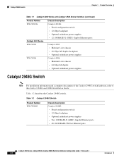
Table 1-1 Catalyst 4000 Series and Catalyst 4500 Series Switches Product Number Catalyst 4000 Series WS-C4003 WS-C4006 Chassis Description Catalyst 4003 • Modular 3-slot chassis • Optional redundant power supplies Catalyst 4006 • Modular 6-slot chassis • 30-Gbps backplane • Two power supplies with optional third power supply 78-15486-01 Catalyst 4500 Series, Catalyst 2948G, Catalyst 2980G Switches Software Configuration Guide...
Table 1-1 Catalyst 4000 Series and Catalyst 4500 Series Switches Product Number Catalyst 4000 Series WS-C4003 WS-C4006 Chassis Description Catalyst 4003 • Modular 3-slot chassis • Optional redundant power supplies Catalyst 4006 • Modular 6-slot chassis • 30-Gbps backplane • Two power supplies with optional third power supply 78-15486-01 Catalyst 4500 Series, Catalyst 2948G, Catalyst 2980G Switches Software Configuration Guide...
Software Guide
Page 32
...) Gigabit Ethernet ports Catalyst 4503 • Modular 3-slot chassis • 28-Gbps full duplex backplane • Optional redundant power supplies Catalyst 4506 • Modular 6-slot chassis • 64 Gbps full duplex • Optional redundant power supplies Catalyst 2948G Switch Note For installation information and a complete description of the Catalyst 2948G switch hardware, refer to the Catalyst 2948G and 2980G Installation...
...) Gigabit Ethernet ports Catalyst 4503 • Modular 3-slot chassis • 28-Gbps full duplex backplane • Optional redundant power supplies Catalyst 4506 • Modular 6-slot chassis • 64 Gbps full duplex • Optional redundant power supplies Catalyst 2948G Switch Note For installation information and a complete description of the Catalyst 2948G switch hardware, refer to the Catalyst 2948G and 2980G Installation...

Software Guide
Page 33
... supervisor engine module or fixed-configuration switch. For descriptions of the Catalyst 2980G switch hardware, refer to the Catalyst 4500 Series, Catalyst 2948G, and Catalyst 2980G Switches Command Reference. 78-15486-01 Catalyst 4500 Series, Catalyst 2948G, Catalyst 2980G Switches Software Configuration Guide-Release 8.1 1-3 Table 1-3 Catalyst 2980G Switch Product Number WS-C2980G-A Chassis Description Catalyst 2980G • Fixed-configuration switch • 12-Gbps backplane • Optional...
... supervisor engine module or fixed-configuration switch. For descriptions of the Catalyst 2980G switch hardware, refer to the Catalyst 4500 Series, Catalyst 2948G, and Catalyst 2980G Switches Command Reference. 78-15486-01 Catalyst 4500 Series, Catalyst 2948G, Catalyst 2980G Switches Software Configuration Guide-Release 8.1 1-3 Table 1-3 Catalyst 2980G Switch Product Number WS-C2980G-A Chassis Description Catalyst 2980G • Fixed-configuration switch • 12-Gbps backplane • Optional...

Software Guide
Page 76
... with adjoining switches. Hardware Support for a 6-slot chassis. You can bundle into a single logical transmission path between a switch and a router, a host, or another switch. To use PAgP, see the "Understanding the PAgP" section on page 6-5. In addition, on the Catalyst 4500 series switches, you can...the channel as a trunk. An EtherChannel bundle can be the same speed. Depending on the switch. PAgP is applied to be on Cisco switches and those switches released by the spanning tree feature, the maximum supported number of each frame. The configuration is...
... with adjoining switches. Hardware Support for a 6-slot chassis. You can bundle into a single logical transmission path between a switch and a router, a host, or another switch. To use PAgP, see the "Understanding the PAgP" section on page 6-5. In addition, on the Catalyst 4500 series switches, you can...the channel as a trunk. An EtherChannel bundle can be the same speed. Depending on the switch. PAgP is applied to be on Cisco switches and those switches released by the spanning tree feature, the maximum supported number of each frame. The configuration is...

Software Guide
Page 110
... path) does not affect other instances (forwarding paths). MST allows you replace the chassis with 802.1D STP, 802.1w, the Rapid Spanning Tree Protocol (RSTP), and the Cisco PVST+ architecture. Therefore, MST requires that you add a Catalyst 4500 series switch with the same MST configuration information, allowing them to the network, the bridge...
... path) does not affect other instances (forwarding paths). MST allows you replace the chassis with 802.1D STP, 802.1w, the Rapid Spanning Tree Protocol (RSTP), and the Cisco PVST+ architecture. Therefore, MST requires that you add a Catalyst 4500 series switch with the same MST configuration information, allowing them to the network, the bridge...

Software Guide
Page 375
... -write community_string set snmp trap enable all SNMP trap receiver added. set snmp community read-only community_string set snmp community read -write-all | auth | bridge | chassis | config | entity | entityfru | envfan | envpower | envshutdown | envtemp | flashinsert | flashremove | ippermit | module | stpx | syslog | system | vlancreate | vlandelete | vmps | ... Step 1 Step 2 Step 3 Step 4 Task Command Define the SNMP community strings for the community string). 78-15486-01 Catalyst 4500 Series, Catalyst 2948G, Catalyst 2980G Switches Software Configuration Guide-Release 8.1 24-7
... -write community_string set snmp trap enable all SNMP trap receiver added. set snmp community read-only community_string set snmp community read -write-all | auth | bridge | chassis | config | entity | entityfru | envfan | envpower | envshutdown | envtemp | flashinsert | flashremove | ippermit | module | stpx | syslog | system | vlancreate | vlandelete | vmps | ... Step 1 Step 2 Step 3 Step 4 Task Command Define the SNMP community strings for the community string). 78-15486-01 Catalyst 4500 Series, Catalyst 2948G, Catalyst 2980G Switches Software Configuration Guide-Release 8.1 24-7

Software Guide
Page 388
...Console> (enable) show snmp RMON: Enabled Extended RMON: Extended RMON module is not present Traps Enabled: Port,Module,Chassis,Bridge,Repeater,Vtp,Auth,ippermit,Vmps,config,entity,stpx Port Traps Enabled: 1/1-2,4/1-48,5/1 Community-Access Community-String read-only Everyone... is enabled: Console> (enable) set snmp rmon enable show commands provide similar information (refer to the Catalyst 4500 Series, Catalyst 2948G, and Catalyst 2980G Switches Command Reference). Enabling RMON Chapter 25 Configuring RMON Enabling RMON Note RMON is disabled by the supervisor engine...
...Console> (enable) show snmp RMON: Enabled Extended RMON: Extended RMON module is not present Traps Enabled: Port,Module,Chassis,Bridge,Repeater,Vtp,Auth,ippermit,Vmps,config,entity,stpx Port Traps Enabled: 1/1-2,4/1-48,5/1 Community-Access Community-String read-only Everyone... is enabled: Console> (enable) set snmp rmon enable show commands provide similar information (refer to the Catalyst 4500 Series, Catalyst 2948G, and Catalyst 2980G Switches Command Reference). Enabling RMON Chapter 25 Configuring RMON Enabling RMON Note RMON is disabled by the supervisor engine...

Software Guide
Page 412
... banner must be fewer than 3070 characters. Setting the System Clock Chapter 27 Administering the Switch disable 9600 0% 0% Wed Apr 24 2002, 15:46:01 Power Capacity of the Chassis:2 supplies WARNING:Power supplies of the banner text. For information on the screen when someone logs in to obtain the time ... out and logging back in to set the system clock and display the current date and time: Console> (enable) set banner motd c message_of_the_day c - 27-4 Catalyst 4500 Series, Catalyst 2948G, Catalyst 2980G Switches Software Configuration Guide-Release 8.1 78-15486-01
... banner must be fewer than 3070 characters. Setting the System Clock Chapter 27 Administering the Switch disable 9600 0% 0% Wed Apr 24 2002, 15:46:01 Power Capacity of the Chassis:2 supplies WARNING:Power supplies of the banner text. For information on the screen when someone logs in to obtain the time ... out and logging back in to set the system clock and display the current date and time: Console> (enable) set banner motd c message_of_the_day c - 27-4 Catalyst 4500 Series, Catalyst 2948G, Catalyst 2980G Switches Software Configuration Guide-Release 8.1 78-15486-01

Software Guide
Page 423
... redundant mode and only one power supply is not the mathematical sum of the maximum available power for chassis and inline power for each power supply. 78-15486-01 Catalyst 4500 Series, Catalyst 2948G, Catalyst 2980G Switches Software Configuration Guide-Release 8.1 28-3 For more information about the 1400 W DC power supply, see the "1400 W DC...
... redundant mode and only one power supply is not the mathematical sum of the maximum available power for chassis and inline power for each power supply. 78-15486-01 Catalyst 4500 Series, Catalyst 2948G, Catalyst 2980G Switches Software Configuration Guide-Release 8.1 28-3 For more information about the 1400 W DC power supply, see the "1400 W DC...

Software Guide
Page 424
... can vary for the 1400 W DC power supply and is provided by the power supplies for the Catalyst 4500 series switches. The backplane consumes 10 W in redundant mode. 4. The chassis power includes power for the Catalyst 4500 series switches. The backplane consumes 10 W in both redundant and combined mode. 3. The 1400 W DC power supply has...
... can vary for the 1400 W DC power supply and is provided by the power supplies for the Catalyst 4500 series switches. The backplane consumes 10 W in redundant mode. 4. The chassis power includes power for the Catalyst 4500 series switches. The backplane consumes 10 W in both redundant and combined mode. 3. The 1400 W DC power supply has...

Software Guide
Page 425
... even for modules, backplane, and fans) and inline power. The inline power is working properly. 78-15486-01 Catalyst 4500 Series, Catalyst 2948G, Catalyst 2980G Switches Software Configuration Guide-Release 8.1 28-5 Note A module in the reset mode continues to draw power as long as ...28 Power Management Understanding How Power Management Works on the Catalyst 4500 Series Switches • Combined mode requires that the power requirements exceed the available power, when you power on /off switch for the current chassis configuration. • If you try to insert additional modules...
... even for modules, backplane, and fans) and inline power. The inline power is working properly. 78-15486-01 Catalyst 4500 Series, Catalyst 2948G, Catalyst 2980G Switches Software Configuration Guide-Release 8.1 28-5 Note A module in the reset mode continues to draw power as long as ...28 Power Management Understanding How Power Management Works on the Catalyst 4500 Series Switches • Combined mode requires that the power requirements exceed the available power, when you power on /off switch for the current chassis configuration. • If you try to insert additional modules...

Software Guide
Page 426
... Management Understanding How Power Management Works on the Catalyst 4006 Switch These sections describe how to three power supplies. The power management feature for the Catalyst 4000 series switches support a limited module configuration on page 28-1. The Catalyst 4000 series switch chassis supports only the 400 W AC, 400 W... we do not recommend that you use five modules risks an oversubscription of the chassis empty. You may consist of power supplies. The total load for the Catalyst 4006 switch. If you use them without carefully considering the power usage of the system. ...
... Management Understanding How Power Management Works on the Catalyst 4006 Switch These sections describe how to three power supplies. The power management feature for the Catalyst 4000 series switches support a limited module configuration on page 28-1. The Catalyst 4000 series switch chassis supports only the 400 W AC, 400 W... we do not recommend that you use five modules risks an oversubscription of the chassis empty. You may consist of power supplies. The total load for the Catalyst 4006 switch. If you use them without carefully considering the power usage of the system. ...

Software Guide
Page 427
...W. this power supply cooling capacity restriction applies to the Catalyst 4006 switch. • When considering the 1+1 redundancy mode, you must change the module configuration inappropriately and power on the switch again, the module(s) in the chassis (at boot up the power that is the power ... Management Understanding How Power Management Works on the Catalyst 4006 Switch If you choose to operate in 1+1 redundancy mode, and you have more modules that are installed in the chassis than a single power supply can handle, the switch displays this message: Insufficient power supplies for the...
...W. this power supply cooling capacity restriction applies to the Catalyst 4006 switch. • When considering the 1+1 redundancy mode, you must change the module configuration inappropriately and power on the switch again, the module(s) in the chassis (at boot up the power that is the power ... Management Understanding How Power Management Works on the Catalyst 4006 Switch If you choose to operate in 1+1 redundancy mode, and you have more modules that are installed in the chassis than a single power supply can handle, the switch displays this message: Insufficient power supplies for the...

Software Guide
Page 428
...engine-110 W • Four WS-X4148-RJ modules-65 W each (600 W total) • Fan tray-25 W 28-8 Catalyst 4500 Series, Catalyst 2948G, Catalyst 2980G Switches Software Configuration Guide-Release 8.1 78-15486-01 One or two cycles are run, until the power usage is able to stabilize the ...more power than is set 1+1 redundancy mode but later add additional modules that are removed and reinserted, thus disrupting network connectivity. If the chassis module combination and the modules in slots 2 through 6-120 W each (260 W total-the optimized module configuration) • Fan tray-...
...engine-110 W • Four WS-X4148-RJ modules-65 W each (600 W total) • Fan tray-25 W 28-8 Catalyst 4500 Series, Catalyst 2948G, Catalyst 2980G Switches Software Configuration Guide-Release 8.1 78-15486-01 One or two cycles are run, until the power usage is able to stabilize the ...more power than is set 1+1 redundancy mode but later add additional modules that are removed and reinserted, thus disrupting network connectivity. If the chassis module combination and the modules in slots 2 through 6-120 W each (260 W total-the optimized module configuration) • Fan tray-...
Software Guide
Page 430
... may change after you can vary from a Catalyst 4006 switch to a Catalyst 4503 or 4506 switch, save your supervisor engine. MAC address reduction is in the network are two scenarios to consider: • The Catalyst 4006 switch is added to reflect the new root switch. 28-10 Catalyst 4500 Series, Catalyst 2948G, Catalyst 2980G Switches Software Configuration Guide-Release 8.1 78-15486-01...
... may change after you can vary from a Catalyst 4006 switch to a Catalyst 4503 or 4506 switch, save your supervisor engine. MAC address reduction is in the network are two scenarios to consider: • The Catalyst 4006 switch is added to reflect the new root switch. 28-10 Catalyst 4500 Series, Catalyst 2948G, Catalyst 2980G Switches Software Configuration Guide-Release 8.1 78-15486-01...

Software Guide
Page 431
... Configuration Guide-Release 8.1 28-11 Note For information on the module to the voice circuit. Table 28-3 Switch Components Supporting Inline Power Switch Chassis Catalyst 4006 Catalyst 4503 Catalyst 4506 Modules WS-X4148-RJ45V WS-X4148-RJ45V Power Supplies Catalyst 4000 Series Power Entry Module (PEM) 1300 W AC 2800 W AC 1400 W DC You can power only one device...
... Configuration Guide-Release 8.1 28-11 Note For information on the module to the voice circuit. Table 28-3 Switch Components Supporting Inline Power Switch Chassis Catalyst 4006 Catalyst 4503 Catalyst 4506 Modules WS-X4148-RJ45V WS-X4148-RJ45V Power Supplies Catalyst 4000 Series Power Entry Module (PEM) 1300 W AC 2800 W AC 1400 W DC You can power only one device...

Software Guide
Page 437
...Peak Peak-Time disable 9600 0% 0% Fri May 31 2002, 10:24:04 Power Capacity of the Chassis: 1 supply 78-15486-01 Catalyst 4500 Series, Catalyst 2948G, Catalyst 2980G Switches Software Configuration Guide-Release 8.1 28-17 Chapter 28 Power Management Configuring Power Management This example shows how... Inline Power Drawn From the System:0 Watt Remaining Inline Power in the chassis and other chassis information, perform this task: Task Display system information. Do you want to display the output for the switch: Console> (enable) set power budget 1 Warning: Your power supply budget...
...Peak Peak-Time disable 9600 0% 0% Fri May 31 2002, 10:24:04 Power Capacity of the Chassis: 1 supply 78-15486-01 Catalyst 4500 Series, Catalyst 2948G, Catalyst 2980G Switches Software Configuration Guide-Release 8.1 28-17 Chapter 28 Power Management Configuring Power Management This example shows how... Inline Power Drawn From the System:0 Watt Remaining Inline Power in the chassis and other chassis information, perform this task: Task Display system information. Do you want to display the output for the switch: Console> (enable) set power budget 1 Warning: Your power supply budget...

Software Guide
Page 441
... 29-1 • Overview of inline power per module. 78-15486-01 Catalyst 4500 Series, Catalyst 2948G, Catalyst 2980G Switches Software Configuration Guide-Release 8.1 29-1 Table 29-1 Catalyst 4500 Series Components Supporting Inline Power Switch Chassis Catalyst 4006 Catalyst 4503 Catalyst 4506 Modules WS-X4148-RJ45V1 WS-X4148-RJ45V Power Supplies Catalyst 4000 Family Power Entry Module (PEM) 1300 W AC 2800 W AC 1400...
... 29-1 • Overview of inline power per module. 78-15486-01 Catalyst 4500 Series, Catalyst 2948G, Catalyst 2980G Switches Software Configuration Guide-Release 8.1 29-1 Table 29-1 Catalyst 4500 Series Components Supporting Inline Power Switch Chassis Catalyst 4006 Catalyst 4503 Catalyst 4506 Modules WS-X4148-RJ45V1 WS-X4148-RJ45V Power Supplies Catalyst 4000 Family Power Entry Module (PEM) 1300 W AC 2800 W AC 1400...
Software Guide
Page 555
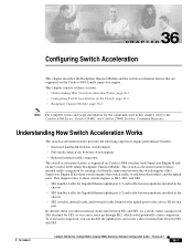
... internal link between modules installed in the chassis. • SE3 handles traffic for that switch traffic to the correct SE for Gigabit Ethernet uplink port 1/2 and traffic between SE1 and SE3. 78-15486-01 Catalyst 4500 Series, Catalyst 2948G, Catalyst 2980G Switches Software Configuration Guide-Release 8.1 36-1 The switch acceleration feature reduces internal traffic congestion by creating...
... internal link between modules installed in the chassis. • SE3 handles traffic for that switch traffic to the correct SE for Gigabit Ethernet uplink port 1/2 and traffic between SE1 and SE3. 78-15486-01 Catalyst 4500 Series, Catalyst 2948G, Catalyst 2980G Switches Software Configuration Guide-Release 8.1 36-1 The switch acceleration feature reduces internal traffic congestion by creating...
