
Installation Guide
Page 2
... B digital devices. IF YOU ARE UNABLE TO LOCATE THE SOFTWARE LICENSE OR LIMITED WARRANTY, CONTACT YOUR CISCO REPRESENTATIVE FOR A COPY. THE SPECIFICATIONS AND INFORMATION REGARDING THE PRODUCTS IN THIS MANUAL ARE SUBJECT TO CHANGE WITHOUT NOTICE. Operation of California.... CISCO AND THE ABOVE-NAMED SUPPLIERS DISCLAIM ALL WARRANTIES, EXPRESSED OR IMPLIED, INCLUDING, WITHOUT LIMITATION, THOSE OF ...
... B digital devices. IF YOU ARE UNABLE TO LOCATE THE SOFTWARE LICENSE OR LIMITED WARRANTY, CONTACT YOUR CISCO REPRESENTATIVE FOR A COPY. THE SPECIFICATIONS AND INFORMATION REGARDING THE PRODUCTS IN THIS MANUAL ARE SUBJECT TO CHANGE WITHOUT NOTICE. Operation of California.... CISCO AND THE ABOVE-NAMED SUPPLIERS DISCLAIM ALL WARRANTIES, EXPRESSED OR IMPLIED, INCLUDING, WITHOUT LIMITATION, THOSE OF ...

Installation Guide
Page 8
... B-1 1000BaseX Ports B-2 Gigastack Port B-3 Console Port B-3 Cable and Adapter Specifications B-4 Crossover and Straight-Through Cable Pinouts B-4 Rollover Cable and Adapter Pinouts B-5 Identifying a Rollover Cable B-5 Connecting to a PC B-6 Connecting to a Terminal B-7 Translated Safety Warnings C-1 Attaching the Cisco RPS (model PWR600-AC-RPS) C-2 Attaching the Cisco RPS (model PWR300-AC-RPS-N1) C-4 Service Personnel Warning...
... B-1 1000BaseX Ports B-2 Gigastack Port B-3 Console Port B-3 Cable and Adapter Specifications B-4 Crossover and Straight-Through Cable Pinouts B-4 Rollover Cable and Adapter Pinouts B-5 Identifying a Rollover Cable B-5 Connecting to a PC B-6 Connecting to a Terminal B-7 Translated Safety Warnings C-1 Attaching the Cisco RPS (model PWR600-AC-RPS) C-2 Attaching the Cisco RPS (model PWR300-AC-RPS-N1) C-4 Service Personnel Warning...

Installation Guide
Page 12
... font. • Information you enter is a physical and functional overview of the switch. Appendix A, "Technical Specifications," lists the physical and environmental specifications for installing a switch on a rack, wall, table, or shelf. Chapter 3, "Troubleshooting," describes how...Switch," contains the procedures for the switches and the regulatory agency approvals. Organization Preface Organization This guide is organized into the following conventions to identify and resolve some of the problems that can be installed suggest possible deployment strategies. Catalyst...
... font. • Information you enter is a physical and functional overview of the switch. Appendix A, "Technical Specifications," lists the physical and environmental specifications for installing a switch on a rack, wall, table, or shelf. Chapter 3, "Troubleshooting," describes how...Switch," contains the procedures for the switches and the regulatory agency approvals. Organization Preface Organization This guide is organized into the following conventions to identify and resolve some of the problems that can be installed suggest possible deployment strategies. Catalyst...

Installation Guide
Page 25
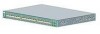
... specific to the Catalyst 3524-PWR XL switch is its ability to provide inline power to Cisco IP Phones. (Phone adapters are not required when connecting to the Catalyst 3524-PWR XL 10/100 switch ports.) Figure 1-1 shows the switch models in different network topologies Features The Catalyst 3500 series XL switches-also referred to as Catalyst 3500 XL switches-are...
... specific to the Catalyst 3524-PWR XL switch is its ability to provide inline power to Cisco IP Phones. (Phone adapters are not required when connecting to the Catalyst 3524-PWR XL 10/100 switch ports.) Figure 1-1 shows the switch models in different network topologies Features The Catalyst 3500 series XL switches-also referred to as Catalyst 3500 XL switches-are...

Installation Guide
Page 32
... a Catalyst 3524-PWR XL 10/100 port automatically provides power when a Cisco IP Phone is connected On a per -port priority override. When connecting the switch to the following phones: Cisco IP Phone 7960, Cisco IP Phone 7940, and Cisco IP Phone 7910 • Automatically detect if a Cisco IP ... capabilities. The 10/100 ports on the Catalyst 3512, 3524, and 3548 XL switches-must be sure that both devices support and full-duplex transmission, if the attached device supports it) and configures itself accordingly. Refer to operate in Appendix B, "Connector and Cable Specifications."
... a Catalyst 3524-PWR XL 10/100 port automatically provides power when a Cisco IP Phone is connected On a per -port priority override. When connecting the switch to the following phones: Cisco IP Phone 7960, Cisco IP Phone 7940, and Cisco IP Phone 7910 • Automatically detect if a Cisco IP ... capabilities. The 10/100 ports on the Catalyst 3512, 3524, and 3548 XL switches-must be sure that both devices support and full-duplex transmission, if the attached device supports it) and configures itself accordingly. Refer to operate in Appendix B, "Connector and Cable Specifications."

Installation Guide
Page 47
... the four DC output power modules. Cisco RPS Connector Specific Cisco RPS models support specific Catalyst 3500 XL switches: • Cisco RPS 600 (model PWR600-AC-RPS)-Supports the Catalyst 3512, 3524, 3548, and 3508 XL switches • Cisco RPS 300 (model PWR300-AC-RPS)-Supports the Catalyst 3524-PWR XL switch RPS Connector on the Catalyst 3508, 3512, 3524, and 3548 XL...
... the four DC output power modules. Cisco RPS Connector Specific Cisco RPS models support specific Catalyst 3500 XL switches: • Cisco RPS 600 (model PWR600-AC-RPS)-Supports the Catalyst 3512, 3524, 3548, and 3508 XL switches • Cisco RPS 300 (model PWR300-AC-RPS)-Supports the Catalyst 3524-PWR XL switch RPS Connector on the Catalyst 3508, 3512, 3524, and 3548 XL...

Installation Guide
Page 48
... the "Cable and Adapter Specifications" section on page B-4. You use to create, monitor, and configure a cluster of four web-based applications that adapter from Cisco. Warning Attach only the Cisco RPS (model PWR300-AC-RPS) to manage individual and standalone switches. Management Options Catalyst 3500 XL switches offer several management options: • Cisco Cluster Management Suite This...
... the "Cable and Adapter Specifications" section on page B-4. You use to create, monitor, and configure a cluster of four web-based applications that adapter from Cisco. Warning Attach only the Cisco RPS (model PWR300-AC-RPS) to manage individual and standalone switches. Management Options Catalyst 3500 XL switches offer several management options: • Cisco Cluster Management Suite This...

Installation Guide
Page 65
... that came with the GigaStack GBIC. • Operating environment is within the ranges listed in Appendix A, "Technical Specifications." 78-6456-04 Catalyst 3500 Series XL Hardware Installation Guide 2-7 Chapter 2 Installing and Starting Up the Switch Hungary Preparing for which special conditions of installation and protection distance are up to the Hungarian EMC Class...
... that came with the GigaStack GBIC. • Operating environment is within the ranges listed in Appendix A, "Technical Specifications." 78-6456-04 Catalyst 3500 Series XL Hardware Installation Guide 2-7 Chapter 2 Installing and Starting Up the Switch Hungary Preparing for which special conditions of installation and protection distance are up to the Hungarian EMC Class...

Installation Guide
Page 81
Chapter 2 Installing and Starting Up the Switch Connecting a PC or Terminal to the Console Port For more information on the GigaStack GBIC connections and configuration scenarios, see the "Cable and Adapter Specifications" section on page B-4. You need to provide a RJ-45-to-DB-25 ...-frequently a PC application such as Hyperterminal or Procomm Plus-makes communication between the switch and your PC- See the Cisco IOS Desktop Switching Software Configuration Guide for instructions. 78-6456-04 Catalyst 3500 Series XL Hardware Installation Guide 2-23 Connecting a PC or Terminal to the...
Chapter 2 Installing and Starting Up the Switch Connecting a PC or Terminal to the Console Port For more information on the GigaStack GBIC connections and configuration scenarios, see the "Cable and Adapter Specifications" section on page B-4. You need to provide a RJ-45-to-DB-25 ...-frequently a PC application such as Hyperterminal or Procomm Plus-makes communication between the switch and your PC- See the Cisco IOS Desktop Switching Software Configuration Guide for instructions. 78-6456-04 Catalyst 3500 Series XL Hardware Installation Guide 2-23 Connecting a PC or Terminal to the...

Installation Guide
Page 84
... Return to a terminal. For console port and adapter pinout information, see the "Cable and Adapter Specifications" section on page B-4. Step 1 Step 2 Step 3 Step 4 Step 5 Step 6 Enter... DTE adapter if you like to the switch console port. You can order a kit (part number ACS-DSBUASYN=) containing that adapter from Cisco. Enter the switch IP address, and press Return: Enter ...bit, and no ]: y If this procedure to create an initial configuration for the switch, and press Return: 2-26 Catalyst 3500 Series XL Hardware Installation Guide 78-6456-04 Use the supplied rollover cable and DB...
... Return to a terminal. For console port and adapter pinout information, see the "Cable and Adapter Specifications" section on page B-4. Step 1 Step 2 Step 3 Step 4 Step 5 Step 6 Enter... DTE adapter if you like to the switch console port. You can order a kit (part number ACS-DSBUASYN=) containing that adapter from Cisco. Enter the switch IP address, and press Return: Enter ...bit, and no ]: y If this procedure to create an initial configuration for the switch, and press Return: 2-26 Catalyst 3500 Series XL Hardware Installation Guide 78-6456-04 Use the supplied rollover cable and DB...

Installation Guide
Page 97
Table A-4 lists the regulatory agency approvals. A A P P E N D I X Technical Specifications 78-6456-04 Table A-1, Table A-2, and Table A-3, list the technical specifications for the Catalyst 3508G XL Switch Environmental Ranges Operating temperature Storage temperature Operating humidity Operating altitude Storage altitude Power Requirements AC input voltage DC ...3A 82.2W 280 Btus per hour 12 lb (5.45 kg) 1.75 x 16 x 17.5 in. (4.45 x 40.46 x 44.45 cm) Catalyst 3500 Series XL Hardware Installation Guide A-1 Table A-1 Technical Specifications for the Catalyst 3500 series XL switches.
Table A-4 lists the regulatory agency approvals. A A P P E N D I X Technical Specifications 78-6456-04 Table A-1, Table A-2, and Table A-3, list the technical specifications for the Catalyst 3508G XL Switch Environmental Ranges Operating temperature Storage temperature Operating humidity Operating altitude Storage altitude Power Requirements AC input voltage DC ...3A 82.2W 280 Btus per hour 12 lb (5.45 kg) 1.75 x 16 x 17.5 in. (4.45 x 40.46 x 44.45 cm) Catalyst 3500 Series XL Hardware Installation Guide A-1 Table A-1 Technical Specifications for the Catalyst 3500 series XL switches.

Installation Guide
Page 98
Appendix A Technical Specifications Table A-2 Technical Specifications for the Catalyst 3512, 3524, and 3548 XL Switches Catalyst 3512 XL Catalyst 3524 XL Catalyst 3548 XL Environmental Ranges Operating temperature 32 to 113°F (0 to 45°C) 32 to 113°F (0 to 45°C) 32 to 113°F (0 to ....82 x 17.5 in. 1.73 x 15.34 x 17.5 in D x W) (4.45 x 30.02 x 44.45 cm) (4.45 x 30.02 x 44.45 cm) (4.39 x 39.0 x 44.45 cm) Catalyst 3500 Series XL Hardware Installation Guide A-2 78-6456-04
Appendix A Technical Specifications Table A-2 Technical Specifications for the Catalyst 3512, 3524, and 3548 XL Switches Catalyst 3512 XL Catalyst 3524 XL Catalyst 3548 XL Environmental Ranges Operating temperature 32 to 113°F (0 to 45°C) 32 to 113°F (0 to 45°C) 32 to 113°F (0 to ....82 x 17.5 in. 1.73 x 15.34 x 17.5 in D x W) (4.45 x 30.02 x 44.45 cm) (4.45 x 30.02 x 44.45 cm) (4.39 x 39.0 x 44.45 cm) Catalyst 3500 Series XL Hardware Installation Guide A-2 78-6456-04

Installation Guide
Page 99
Appendix A Technical Specifications Table A-3 Technical Specifications for the Catalyst 3524-PWR XL Switch Environmental Ranges Operating temperature 32 to 113°F (0 to 45°C) Storage temperature -4 to 149°F (-10 to 65°C) Operating humidity 10 to 85% (... Power consumption 100 to 127/200 to 240 VAC (autoranging) 50 to NOM-019-SCFI CE Marking CE Marking 78-6456-04 Catalyst 3500 Series XL Hardware Installation Guide A-3 Table A-4 Catalyst 3500 Series XL Agency Approvals Safety EMC UL to UL 1950, Third Edition FCC Part 15 Class A c-UL to CAN/CSA...
Appendix A Technical Specifications Table A-3 Technical Specifications for the Catalyst 3524-PWR XL Switch Environmental Ranges Operating temperature 32 to 113°F (0 to 45°C) Storage temperature -4 to 149°F (-10 to 65°C) Operating humidity 10 to 85% (... Power consumption 100 to 127/200 to 240 VAC (autoranging) 50 to NOM-019-SCFI CE Marking CE Marking 78-6456-04 Catalyst 3500 Series XL Hardware Installation Guide A-3 Table A-4 Catalyst 3500 Series XL Agency Approvals Safety EMC UL to UL 1950, Third Edition FCC Part 15 Class A c-UL to CAN/CSA...

Installation Guide
Page 100
Appendix A Technical Specifications Catalyst 3500 Series XL Hardware Installation Guide A-4 78-6456-04
Appendix A Technical Specifications Catalyst 3500 Series XL Hardware Installation Guide A-4 78-6456-04

Installation Guide
Page 101
... adapter can be attached to compatible workstations, servers, routers, and Cisco IP Phones, you must use a crossover cable. (Figure B-4 illustrates the crossover cable schematics.) Note Use a straight-through cable schematics). APPENDIX B Connector and Cable Specifications This appendix describes the Catalyst 3500 XL switch ports and the cables and adapters that you use standard RJ...
... adapter can be attached to compatible workstations, servers, routers, and Cisco IP Phones, you must use a crossover cable. (Figure B-4 illustrates the crossover cable schematics.) Note Use a straight-through cable schematics). APPENDIX B Connector and Cable Specifications This appendix describes the Catalyst 3500 XL switch ports and the cables and adapters that you use standard RJ...

Installation Guide
Page 102
Connector Specifications Appendix B Connector and Cable Specifications Figure B-1 10/100 Port Pinouts Pin Label 1 RD+ 2 RD- 3 TD+ 4 NC 5 NC 6 TD- 7 NC 8 NC 12345678 H5318 1000BaseX Ports 1000BaseX ports use duplex SC connectors, as shown in Figure B-2. Figure B-2 1000BaseX SC Connector H8707 Tx Rx Catalyst 3500 Series XL Hardware Installation Guide B-2 78-6456-04
Connector Specifications Appendix B Connector and Cable Specifications Figure B-1 10/100 Port Pinouts Pin Label 1 RD+ 2 RD- 3 TD+ 4 NC 5 NC 6 TD- 7 NC 8 NC 12345678 H5318 1000BaseX Ports 1000BaseX ports use duplex SC connectors, as shown in Figure B-2. Figure B-2 1000BaseX SC Connector H8707 Tx Rx Catalyst 3500 Series XL Hardware Installation Guide B-2 78-6456-04

Installation Guide
Page 103
... the GigaStack GBIC. Figure B-3 GigaStack Connector 22084 The GigaStack GBIC cables are used to connect the console port of the switch to a terminal. Console Port The console port uses an 8-pin RJ-45 connector, described in Figure B-3. You need to...switch console port to a console PC. You can order a kit (part number ACS-DSBUASYN=) containing that adapter from Cisco. For console port and adapter pinout information, see Table B-1 and Table B-2. 78-6456-04 Catalyst 3500 Series XL Hardware Installation Guide B-3 Appendix B Connector and Cable Specifications Connector Specifications...
... the GigaStack GBIC. Figure B-3 GigaStack Connector 22084 The GigaStack GBIC cables are used to connect the console port of the switch to a terminal. Console Port The console port uses an 8-pin RJ-45 connector, described in Figure B-3. You need to...switch console port to a console PC. You can order a kit (part number ACS-DSBUASYN=) containing that adapter from Cisco. For console port and adapter pinout information, see Table B-1 and Table B-2. 78-6456-04 Catalyst 3500 Series XL Hardware Installation Guide B-3 Appendix B Connector and Cable Specifications Connector Specifications...

Installation Guide
Page 104
Cable and Adapter Specifications Appendix B Connector and Cable Specifications Cable and Adapter Specifications Crossover and Straight-Through Cable Pinouts The schematics of crossover and straight-through cables are shown in Figure B-4 and Figure B-5. H5579 Figure B-5 Straight-Through Cable Schematic Switch 3 TD+ 6 TD- Figure B-4 Crossover Cable Schematic Switch 3 TD+ 6 TD- Switch 3 TD+ 6 TD- 1 RD+ 2 RD- 1 RD+ 2 RD- Switch 3 RD+ 6 RD- 1 RD+ 2 RD- 1 TD+ 2 TD- H5578 Catalyst 3500 Series XL Hardware Installation Guide B-4 78-6456-04
Cable and Adapter Specifications Appendix B Connector and Cable Specifications Cable and Adapter Specifications Crossover and Straight-Through Cable Pinouts The schematics of crossover and straight-through cables are shown in Figure B-4 and Figure B-5. H5579 Figure B-5 Straight-Through Cable Schematic Switch 3 TD+ 6 TD- Figure B-4 Crossover Cable Schematic Switch 3 TD+ 6 TD- Switch 3 TD+ 6 TD- 1 RD+ 2 RD- 1 RD+ 2 RD- Switch 3 RD+ 6 RD- 1 RD+ 2 RD- 1 TD+ 2 TD- H5578 Catalyst 3500 Series XL Hardware Installation Guide B-4 78-6456-04

Installation Guide
Page 105
Figure B-6 Identifying a Rollover Cable Pin 1 Pin 1 on one connector and pin 8 on the other connector should be the same color. Appendix B Connector and Cable Specifications Cable and Adapter Specifications Rollover Cable and Adapter Pinouts Identifying a Rollover Cable To identify a rollover cable, compare the two modular ends of the right plug (see Figure B-6). Hold... left plug should be the same color as the wire connected to the pin on the outside of the cable. Pin 8 H10632 78-6456-04 Catalyst 3500 Series XL Hardware Installation Guide B-5
Figure B-6 Identifying a Rollover Cable Pin 1 Pin 1 on one connector and pin 8 on the other connector should be the same color. Appendix B Connector and Cable Specifications Cable and Adapter Specifications Rollover Cable and Adapter Pinouts Identifying a Rollover Cable To identify a rollover cable, compare the two modular ends of the right plug (see Figure B-6). Hold... left plug should be the same color as the wire connected to the pin on the outside of the cable. Pin 8 H10632 78-6456-04 Catalyst 3500 Series XL Hardware Installation Guide B-5

Installation Guide
Page 106
Figure B-7 Connecting the Console Port to a PC PC Catalyst 3500 series XL switch 22003 RJ-45-to-RJ-45 rollover cable RJ-45-to-DB-9 adapter (labeled TERMINAL) Table B-1 Console Port Signaling and Cabling Using a DB-9 Adapter Console ... Device Signal CTS DSR RxD GND GND TxD DTR RTS Catalyst 3500 Series XL Hardware Installation Guide B-6 78-6456-04 Figure B-7 shows how to connect the console port to a PC running terminal-emulation software. Cable and Adapter Specifications Appendix B Connector and Cable Specifications Connecting to a PC Use the supplied thin, flat, RJ-45...
Figure B-7 Connecting the Console Port to a PC PC Catalyst 3500 series XL switch 22003 RJ-45-to-RJ-45 rollover cable RJ-45-to-DB-9 adapter (labeled TERMINAL) Table B-1 Console Port Signaling and Cabling Using a DB-9 Adapter Console ... Device Signal CTS DSR RxD GND GND TxD DTR RTS Catalyst 3500 Series XL Hardware Installation Guide B-6 78-6456-04 Figure B-7 shows how to connect the console port to a PC running terminal-emulation software. Cable and Adapter Specifications Appendix B Connector and Cable Specifications Connecting to a PC Use the supplied thin, flat, RJ-45...