Installation Guide
Page 13
... de waarschuwing die bij het apparaat wordt geleverd, wilt raadplegen. Use the statement number provided at the end of each warning to materials not contained in this device. BEWAAR DEZE INSTRUCTIES 78-6456-04 Catalyst 3500 Series XL Hardware Installation Guide xiii You are in een situatie die lichamelijk letsel kan veroorzaken...
... de waarschuwing die bij het apparaat wordt geleverd, wilt raadplegen. Use the statement number provided at the end of each warning to materials not contained in this device. BEWAAR DEZE INSTRUCTIES 78-6456-04 Catalyst 3500 Series XL Hardware Installation Guide xiii You are in een situatie die lichamelijk letsel kan veroorzaken...

Installation Guide
Page 47
..., and 3508 XL switches • Cisco RPS 300 (model PWR300-AC-RPS)-Supports the Catalyst 3524-PWR XL switch RPS Connector on the Catalyst 3508, 3512, 3524, and 3548 XL Switches The Cisco RPS 600 (model PWR600-AC-RPS) provides a quasi-redundant power source for the Cisco RPS and one connector at each cable end) to connect four external...
..., and 3508 XL switches • Cisco RPS 300 (model PWR300-AC-RPS)-Supports the Catalyst 3524-PWR XL switch RPS Connector on the Catalyst 3508, 3512, 3524, and 3548 XL Switches The Cisco RPS 600 (model PWR600-AC-RPS) provides a quasi-redundant power source for the Cisco RPS and one connector at each cable end) to connect four external...
Installation Guide
Page 75
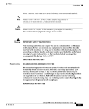
If you are using the RPS, see the "Power Connectors" section on page 1-22 and the Cisco RPS documentation. When the switch begins POST, the port LEDs turn amber for 2 seconds, and then they turn as ProComm, HyperTerminal, tip, or minicom) from your configuration has... software program (such as the system completes a test. 78-6456-04 Catalyst 3500 Series XL Hardware Installation Guide 2-17 Connect the other end of the unit. The port LEDs for installation instructions. Attach the four rubber feet to install the switch on a table or shelf: Step 1 Step 2 Step 3 Locate the...
If you are using the RPS, see the "Power Connectors" section on page 1-22 and the Cisco RPS documentation. When the switch begins POST, the port LEDs turn amber for 2 seconds, and then they turn as ProComm, HyperTerminal, tip, or minicom) from your configuration has... software program (such as the system completes a test. 78-6456-04 Catalyst 3500 Series XL Hardware Installation Guide 2-17 Connect the other end of the unit. The port LEDs for installation instructions. Attach the four rubber feet to install the switch on a table or shelf: Step 1 Step 2 Step 3 Locate the...
Installation Guide
Page 76
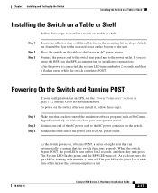
... the 10/100 ports on both ends of these methods for configuring the 10/100 Ethernet ports: • Let the ports autonegotiate both speed and duplex. • Set the port speed and duplex parameters on the Catalyst 3524-PWR XL switch to either automatically provide inline power when a Cisco IP Phone is connected or...
... the 10/100 ports on both ends of these methods for configuring the 10/100 Ethernet ports: • Let the ports autonegotiate both speed and duplex. • Set the port speed and duplex parameters on the Catalyst 3524-PWR XL switch to either automatically provide inline power when a Cisco IP Phone is connected or...
Installation Guide
Page 78
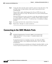
... for loops. Connecting to the GBIC Module Ports Chapter 2 Installing and Starting Up the Switch Step 2 Step 3 Step 4 Connect the other end of the cable to an RJ-45 connector of the other end might not be a cable problem or a problem with the adapter installed in the "... section on installing and cabling the GigaStack GBICs, see the Catalyst GigaStack Gigabit Interface Converter Hardware Installation Guide. 2-20 Catalyst 3500 Series XL Hardware Installation Guide 78-6456-04 The port LED comes on when both the switch and the connected device have established link. Repeat steps 1 ...
... for loops. Connecting to the GBIC Module Ports Chapter 2 Installing and Starting Up the Switch Step 2 Step 3 Step 4 Connect the other end of the cable to an RJ-45 connector of the other end might not be a cable problem or a problem with the adapter installed in the "... section on installing and cabling the GigaStack GBICs, see the Catalyst GigaStack Gigabit Interface Converter Hardware Installation Guide. 2-20 Catalyst 3500 Series XL Hardware Installation Guide 78-6456-04 The port LED comes on when both the switch and the connected device have established link. Repeat steps 1 ...
Installation Guide
Page 82
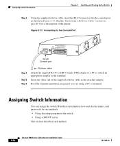
Insert the other end of the pinout. See the "Identifying a Rollover Cable" section on page B-5 for a description of the supplied rollover cable in the switch • Using a BOOTP server This section describes each method. 2-24 Catalyst 3500 Series XL Hardware Installation Guide 78-6456-04 Assigning Switch Information You can assign the switch IP address information...
Insert the other end of the pinout. See the "Identifying a Rollover Cable" section on page B-5 for a description of the supplied rollover cable in the switch • Using a BOOTP server This section describes each method. 2-24 Catalyst 3500 Series XL Hardware Installation Guide 78-6456-04 Assigning Switch Information You can assign the switch IP address information...
Installation Guide
Page 86
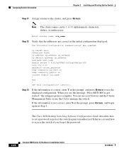
... password. 2-28 Catalyst 3500 Series XL Hardware Installation Guide 78-6456-04 If the information is complete. end ! The Cisco IOS Desktop Switching Software Configuration Guide describes how to set a password to protect the switch against unauthorized Telnet access and how to access the switch if you see the... the prompt, and press Return to use the CLI to 31 alphanumeric characters, dashes, or underscores. Assigning Switch Information Chapter 2 Installing and Starting Up the Switch Step 11 Assign a name to the cluster, and press Return: Note The cluster name can use your ...
... password. 2-28 Catalyst 3500 Series XL Hardware Installation Guide 78-6456-04 If the information is complete. end ! The Cisco IOS Desktop Switching Software Configuration Guide describes how to set a password to protect the switch against unauthorized Telnet access and how to access the switch if you see the... the prompt, and press Return to use the CLI to 31 alphanumeric characters, dashes, or underscores. Assigning Switch Information Chapter 2 Installing and Starting Up the Switch Step 11 Assign a name to the cluster, and press Return: Note The cluster name can use your ...
Installation Guide
Page 94
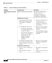
...Catalyst 3500 Series XL Hardware Installation Guide 3-4 78-6456-04 See the Cisco IOS Desktop Switching Software Configuration Guide for information on identifying autonegotiation mismatches. Cabling distance exceeded. • Port statistics show excessive frame check sequence (FCS), late-collision, or alignment errors. • See the Cisco IOS Desktop Switching... Software Configuration Guide for information on displaying port statistics. • For 100BaseTX connections: - The distance between the two end stations exceeds the 100BaseT...
...Catalyst 3500 Series XL Hardware Installation Guide 3-4 78-6456-04 See the Cisco IOS Desktop Switching Software Configuration Guide for information on identifying autonegotiation mismatches. Cabling distance exceeded. • Port statistics show excessive frame check sequence (FCS), late-collision, or alignment errors. • See the Cisco IOS Desktop Switching... Software Configuration Guide for information on displaying port statistics. • For 100BaseTX connections: - The distance between the two end stations exceeds the 100BaseT...
Installation Guide
Page 95
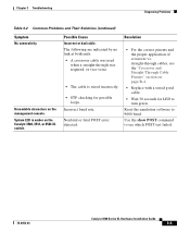
.... Incorrect baud rate. Nonfatal or fatal POST error detected. Possible Cause Incorrect or bad cable. The following are indicated by no link at both ends: • A crossover cable was required, or vice-versa. • The cable is amber on the management console. System LED is wired ... • STP checking for LED to turn green. Use the show POST command to 9600 baud. Unreadable characters on the Catalyst 3508, 3512, or 3524 XL switch. Resolution • For the correct pinouts and the proper application of crossover vs. Reset the emulation software to see the ...
.... Incorrect baud rate. Nonfatal or fatal POST error detected. Possible Cause Incorrect or bad cable. The following are indicated by no link at both ends: • A crossover cable was required, or vice-versa. • The cable is amber on the management console. System LED is wired ... • STP checking for LED to turn green. Use the show POST command to 9600 baud. Unreadable characters on the Catalyst 3508, 3512, or 3524 XL switch. Resolution • For the correct pinouts and the proper application of crossover vs. Reset the emulation software to see the ...

Installation Guide
Page 105
... and Adapter Pinouts Identifying a Rollover Cable To identify a rollover cable, compare the two modular ends of the right plug (see Figure B-6). Hold the cable ends side-by-side, with the tab at the back. Pin 8 H10632 78-6456-04 Catalyst 3500 Series XL Hardware Installation Guide B-5 Figure B-6 Identifying a Rollover Cable Pin 1 Pin 1 on...
... and Adapter Pinouts Identifying a Rollover Cable To identify a rollover cable, compare the two modular ends of the right plug (see Figure B-6). Hold the cable ends side-by-side, with the tab at the back. Pin 8 H10632 78-6456-04 Catalyst 3500 Series XL Hardware Installation Guide B-5 Figure B-6 Identifying a Rollover Cable Pin 1 Pin 1 on...