Hardware Installation Guide
Page 19
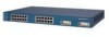
... Catalyst 3500 Series XL Hardware Installation Guide 1-1 A feature specific to the Catalyst 3524-PWR XL switch is its ability to provide inline power to Cisco IP Phones. (Phone adapters are stackable 10/100 Ethernet switches to the Catalyst 3524-PWR XL 10/100 switch ports.) Figure 1-1 shows the switch models in different network topologies Features The Catalyst 3500 series XL switches-also referred to as Catalyst 3500 XL switches...
... Catalyst 3500 Series XL Hardware Installation Guide 1-1 A feature specific to the Catalyst 3524-PWR XL switch is its ability to provide inline power to Cisco IP Phones. (Phone adapters are stackable 10/100 Ethernet switches to the Catalyst 3524-PWR XL 10/100 switch ports.) Figure 1-1 shows the switch models in different network topologies Features The Catalyst 3500 series XL switches-also referred to as Catalyst 3500 XL switches...
Hardware Installation Guide
Page 23
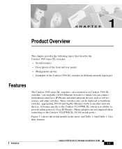
... on AC input and supplies DC output to the Catalyst 3512, 3524, and 3548 XL switches • Connection for optional Cisco RPS 300 that operates on AC input and supplies DC output to the Catalyst 3524-PWR XL switch Inline Power (Catalyst 3524-PWR XL switch only) • Ability to provide inline power for Cisco IP Phones from all 24 10/100 Ethernet ports...
... on AC input and supplies DC output to the Catalyst 3512, 3524, and 3548 XL switches • Connection for optional Cisco RPS 300 that operates on AC input and supplies DC output to the Catalyst 3524-PWR XL switch Inline Power (Catalyst 3524-PWR XL switch only) • Ability to provide inline power for Cisco IP Phones from all 24 10/100 Ethernet ports...
Hardware Installation Guide
Page 24
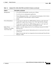
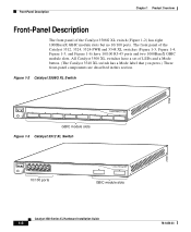
... panel of LEDs and a Mode button. (The Catalyst 3548 XL switch has a Mode label that you press.) These front-panel components are described in this section. The front panel of the Catalyst 3512, 3524, 3524-PWR and 3548 XL switches (Figure 1-3, Figure 1-4, Figure 1-5, and Figure 1-6) have a set of the Catalyst 3508G XL switch (Figure 1-2) has eight 1000BaseX GBIC module slots but...
... panel of LEDs and a Mode button. (The Catalyst 3548 XL switch has a Mode label that you press.) These front-panel components are described in this section. The front panel of the Catalyst 3512, 3524, 3524-PWR and 3548 XL switches (Figure 1-3, Figure 1-4, Figure 1-5, and Figure 1-6) have a set of the Catalyst 3508G XL switch (Figure 1-2) has eight 1000BaseX GBIC module slots but...
Hardware Installation Guide
Page 25
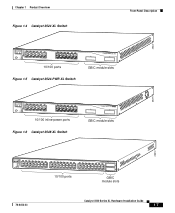
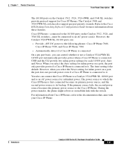
Chapter 1 Product Overview Figure 1-4 Catalyst 3524 XL Switch Front-Panel Description 26237 12 1X 34 56 78 MODE SYSTEM RPS STATUS 2X UTIL DUPLX SPEED 9 10 11 12 11X 12X 13 14 13X 15 16 17 18 19 20 21 22 23 24 23X 14X 24X 10/100 ports Figure 1-5 Catalyst 3524-PWR XL Switch 1 2 GBIC module slots 30291...
Chapter 1 Product Overview Figure 1-4 Catalyst 3524 XL Switch Front-Panel Description 26237 12 1X 34 56 78 MODE SYSTEM RPS STATUS 2X UTIL DUPLX SPEED 9 10 11 12 11X 12X 13 14 13X 15 16 17 18 19 20 21 22 23 24 23X 14X 24X 10/100 ports Figure 1-5 Catalyst 3524-PWR XL Switch 1 2 GBIC module slots 30291...
Hardware Installation Guide
Page 27
... a Catalyst 3524-PWR XL 10/100 port and to it . CMS and the CLI provide two inline power settings for Cisco IP Phones. Chapter 1 Product Overview Front-Panel Description The 10/100 ports on the Catalyst 3512, 3524, 3524-PWR, and 3548 XL switches provide protocol support for each 10/100 port: Auto and Never. The Catalyst 3548 and 3524-PWR XL switches...
... a Catalyst 3524-PWR XL 10/100 port and to it . CMS and the CLI provide two inline power settings for Cisco IP Phones. Chapter 1 Product Overview Front-Panel Description The 10/100 ports on the Catalyst 3512, 3524, 3524-PWR, and 3548 XL switches provide protocol support for each 10/100 port: Auto and Never. The Catalyst 3548 and 3524-PWR XL switches...
Hardware Installation Guide
Page 28
... • 1000BaseZX GBIC module for fiber connections of up to nine Catalyst 3500 XL switches. Using the required Cisco proprietary signaling and cabling, the maximum distance for a GigaStack GBIC-to eight GBICs in the Catalyst 3508G XL switch. The GigaStack GBIC supports one full-duplex link (in a point-to...) or up to -GigaStack GBIC connection is inserted into a GBIC module slot on these switches, but you can install up to two GBICs in the Catalyst 3512, 3524, 3524-PWR and 3548 XL switches and up to nine half-duplex links (in a stack configuration) to other Gigabit Ethernet devices...
... • 1000BaseZX GBIC module for fiber connections of up to nine Catalyst 3500 XL switches. Using the required Cisco proprietary signaling and cabling, the maximum distance for a GigaStack GBIC-to eight GBICs in the Catalyst 3508G XL switch. The GigaStack GBIC supports one full-duplex link (in a point-to...) or up to -GigaStack GBIC connection is inserted into a GBIC module slot on these switches, but you can install up to two GBICs in the Catalyst 3512, 3524, 3524-PWR and 3548 XL switches and up to nine half-duplex links (in a stack configuration) to other Gigabit Ethernet devices...
Hardware Installation Guide
Page 31
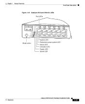
Chapter 1 Product Overview Figure 1-10 Catalyst 3512 and 3524 XL LEDs Port LEDs Front-Panel Description 22028 MODE SYSTEM RPS STATUS UTIL DUPLX SPEED Mode button 12 1X 34 56 78 9 10 11 12 11X 2X 12X System LED Redundant power system LED Status LED Utilization LED Duplex LED Speed LED 78-6456-03 Catalyst 3500 Series XL Hardware Installation Guide 1-13
Chapter 1 Product Overview Figure 1-10 Catalyst 3512 and 3524 XL LEDs Port LEDs Front-Panel Description 22028 MODE SYSTEM RPS STATUS UTIL DUPLX SPEED Mode button 12 1X 34 56 78 9 10 11 12 11X 2X 12X System LED Redundant power system LED Status LED Utilization LED Duplex LED Speed LED 78-6456-03 Catalyst 3500 Series XL Hardware Installation Guide 1-13
Hardware Installation Guide
Page 32
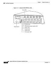
Front-Panel Description Figure 1-11 Catalyst 3524-PWR XL LEDs Port LEDs Chapter 1 Product Overview 30292 MODE SYSTEM RPS STATUS DUPLX SPEED LINE PWR Mode button 12 1X 34 56 78 9 10 11 12 11X 2X 12X System LED Redundant power system LED Status LED Duplex LED Speed LED Line power LED 1-14 Catalyst 3500 Series XL Hardware Installation Guide 78-6456-03
Front-Panel Description Figure 1-11 Catalyst 3524-PWR XL LEDs Port LEDs Chapter 1 Product Overview 30292 MODE SYSTEM RPS STATUS DUPLX SPEED LINE PWR Mode button 12 1X 34 56 78 9 10 11 12 11X 2X 12X System LED Redundant power system LED Status LED Duplex LED Speed LED Line power LED 1-14 Catalyst 3500 Series XL Hardware Installation Guide 78-6456-03
Hardware Installation Guide
Page 34
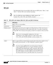
...LED colors and their meanings. Note This is connected but not functioning properly. Note The Cisco RPS 600 (model PWR600-AC-RPS) supports the Catalyst 3512, 3524, 3548, and 3508 XL switches. RPS and the switch AC power supply are using power from the RPS. One of the RPS shows the ...revision level. 1-16 Catalyst 3500 Series XL Hardware Installation Guide 78-6456-03 For more information see the "RPS Connector on the Catalyst 3508, 3512, 3524, and 3548 XL Switches" section on . Amber RPS is not a recommended configuration. The label ...
...LED colors and their meanings. Note This is connected but not functioning properly. Note The Cisco RPS 600 (model PWR600-AC-RPS) supports the Catalyst 3512, 3524, 3548, and 3508 XL switches. RPS and the switch AC power supply are using power from the RPS. One of the RPS shows the ...revision level. 1-16 Catalyst 3500 Series XL Hardware Installation Guide 78-6456-03 For more information see the "RPS Connector on the Catalyst 3508, 3512, 3524, and 3548 XL Switches" section on . Amber RPS is not a recommended configuration. The label ...
Hardware Installation Guide
Page 35
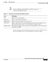
Chapter 1 Product Overview Front-Panel Description Note The Cisco RPS 300 (model PWR300-AC-RPS) supports the Catalyst 3524-PWR XL switch. RPS is connected but not functioning properly. RPS is connected and operational. One of the switch is down , or a fan on the RPS could have failed. For more information about the failure conditions on the...
Chapter 1 Product Overview Front-Panel Description Note The Cisco RPS 300 (model PWR300-AC-RPS) supports the Catalyst 3524-PWR XL switch. RPS is connected but not functioning properly. RPS is connected and operational. One of the switch is down , or a fan on the RPS could have failed. For more information about the failure conditions on the...
Hardware Installation Guide
Page 38
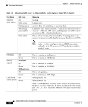
... only when the switch port is transmitting or receiving data. Port is not operating. DUPLEX Off Green SPEED (speed) 10/100 ports Off Green 1000BaseX ports Off Green LINE PWR Off (inline power) Green Port is off . Port is not forwarding. If the Cisco IP Phone is...Mbps. Port is reconfigured, the port LED can affect connectivity, and errors such as STP checks the switch for up to the switch port. Activity. Port is on the Catalyst 3524-PWR XL Switch Port Mode STATUS (port status) LED Color Off Solid green Flashing green Alternating green-amber Solid amber ...
... only when the switch port is transmitting or receiving data. Port is not operating. DUPLEX Off Green SPEED (speed) 10/100 ports Off Green 1000BaseX ports Off Green LINE PWR Off (inline power) Green Port is off . Port is not forwarding. If the Cisco IP Phone is...Mbps. Port is reconfigured, the port LED can affect connectivity, and errors such as STP checks the switch for up to the switch port. Activity. Port is on the Catalyst 3524-PWR XL Switch Port Mode STATUS (port status) LED Color Off Solid green Flashing green Alternating green-amber Solid amber ...
Hardware Installation Guide
Page 39
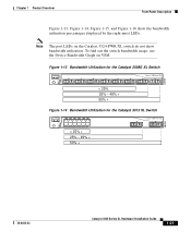
... utilization. Figure 1-13 Bandwidth Utilization for the Catalyst 3508G XL Switch 1 MODE SYSTEM RPS STATUS UTIL DUPLX SPEED 2 3 4 5 Catalyst 3500 XL 6 7 8 < 25% 25% - 49% + 50% + Figure 1-14 Bandwidth Utilization for the Catalyst 3512 XL Switch MODE SYSTEM RPS STATUS UTIL DUPLX SPEED 12 ...25% - 49% + 50% + Catalyst 3500 XL 1 2 38399 78-6456-03 Catalyst 3500 Series XL Hardware Installation Guide 1-21 To find out the switch bandwidth usage, use the Device Bandwidth Graph on the Catalyst 3524-PWR XL switch do not show the bandwidth utilization percentages displayed...
... utilization. Figure 1-13 Bandwidth Utilization for the Catalyst 3508G XL Switch 1 MODE SYSTEM RPS STATUS UTIL DUPLX SPEED 2 3 4 5 Catalyst 3500 XL 6 7 8 < 25% 25% - 49% + 50% + Figure 1-14 Bandwidth Utilization for the Catalyst 3512 XL Switch MODE SYSTEM RPS STATUS UTIL DUPLX SPEED 12 ...25% - 49% + 50% + Catalyst 3500 XL 1 2 38399 78-6456-03 Catalyst 3500 Series XL Hardware Installation Guide 1-21 To find out the switch bandwidth usage, use the Device Bandwidth Graph on the Catalyst 3524-PWR XL switch do not show the bandwidth utilization percentages displayed...
Hardware Installation Guide
Page 40
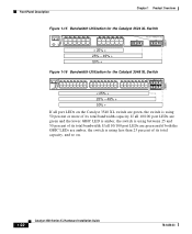
... using 50 percent or more of its total bandwidth capacity. Front-Panel Description Chapter 1 Product Overview 22007 Figure 1-15 Bandwidth Utilization for the Catalyst 3524 XL Switch MODE SYSTEM RPS STATUS UTIL DUPLX SPEED 12 1X 34 56 78 9 10 11 12 11X 2X 12X 13 14 15 16 13X 17 18 ...19 20 21 22 23 24 15X 14X 16X < 25% + 25% - 49% + 50% + Catalyst 3500 XL 1 2 Figure 1-16 Bandwidth Utilization for the Catalyst 3548 XL Switch 28366 SYSTEM RPS STATUS UTIL DUPLX SPEED MODE 12 1X 3 24 56 78 9 10 11 12 13 14 15 16 15X...
... using 50 percent or more of its total bandwidth capacity. Front-Panel Description Chapter 1 Product Overview 22007 Figure 1-15 Bandwidth Utilization for the Catalyst 3524 XL Switch MODE SYSTEM RPS STATUS UTIL DUPLX SPEED 12 1X 34 56 78 9 10 11 12 11X 2X 12X 13 14 15 16 13X 17 18 ...19 20 21 22 23 24 15X 14X 16X < 25% + 25% - 49% + 50% + Catalyst 3500 XL 1 2 Figure 1-16 Bandwidth Utilization for the Catalyst 3548 XL Switch 28366 SYSTEM RPS STATUS UTIL DUPLX SPEED MODE 12 1X 3 24 56 78 9 10 11 12 13 14 15 16 15X...
Hardware Installation Guide
Page 41
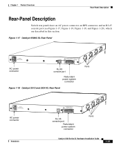
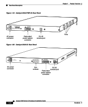
....T+E3P.3OVW***E@R1S4UAP, PLY DC INPUT +12V***@3A AC power connector RJ-45 console port Redundant power system connector Figure 1-18 Catalyst 3512 and 3524 XL Rear Panel Fans 18964 RATING 100-127/200-240V~ 1.0A/0.5A 50-60HZ AC power connector 78-6456-03 CONSOLE DC INPUTS... MANUAL. +5V @24A, +12V @.5A RJ-45 console port Redundant power system connector Fans Catalyst 3500 Series XL Hardware Installation Guide 1-23 Chapter 1 Product Overview Rear-Panel Description Rear-Panel Description Switch rear panels have an AC power connector, an RPS connector, and an RJ-45 console port ...
....T+E3P.3OVW***E@R1S4UAP, PLY DC INPUT +12V***@3A AC power connector RJ-45 console port Redundant power system connector Figure 1-18 Catalyst 3512 and 3524 XL Rear Panel Fans 18964 RATING 100-127/200-240V~ 1.0A/0.5A 50-60HZ AC power connector 78-6456-03 CONSOLE DC INPUTS... MANUAL. +5V @24A, +12V @.5A RJ-45 console port Redundant power system connector Fans Catalyst 3500 Series XL Hardware Installation Guide 1-23 Chapter 1 Product Overview Rear-Panel Description Rear-Panel Description Switch rear panels have an AC power connector, an RPS connector, and an RJ-45 console port ...
Hardware Installation Guide
Page 42
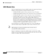
Rear-Panel Description Figure 1-19 Catalyst 3524-PWR XL Rear Panel RATING 100-127/200-240V~ 3.5A/1.8A 50-60HZ DC INPUTS FOR REMOTE POWER SUPPLY SPECIFIED IN MANUAL. -48V @3A, +12V @6A CONSOLE AC power connector Redundant power system connector RJ-45 console port Figure 1-20 Catalyst 3548 XL Rear Panel Chapter 1 Product Overview Fans... DC INPUTS FOR REMOTE POWER SUPPLY SPECIFIED IN MANUAL +3.3V @17A, +12 @1.1A CONSOLE Fan exhaust RJ-45 console port Redundant power system connector 1-24 Catalyst 3500 Series XL Hardware Installation Guide 78-6456-03
Rear-Panel Description Figure 1-19 Catalyst 3524-PWR XL Rear Panel RATING 100-127/200-240V~ 3.5A/1.8A 50-60HZ DC INPUTS FOR REMOTE POWER SUPPLY SPECIFIED IN MANUAL. -48V @3A, +12V @6A CONSOLE AC power connector Redundant power system connector RJ-45 console port Figure 1-20 Catalyst 3548 XL Rear Panel Chapter 1 Product Overview Fans... DC INPUTS FOR REMOTE POWER SUPPLY SPECIFIED IN MANUAL +3.3V @17A, +12 @1.1A CONSOLE Fan exhaust RJ-45 console port Redundant power system connector 1-24 Catalyst 3500 Series XL Hardware Installation Guide 78-6456-03

Hardware Installation Guide
Page 43
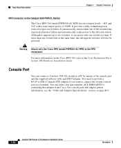
... external devices is not recommended. Cisco RPS Connector Specific Cisco RPS models support specific Catalyst 3500 XL switches: • Cisco RPS 600 (model PWR600-AC-RPS)-Supports the Catalyst 3512, 3524, 3548, and 3508 XL switches • Cisco RPS 300 (model PWR300-AC-RPS)-Supports the Catalyst 3524-PWR XL switch RPS Connector on the Catalyst 3508, 3512, 3524, and 3548 XL Switches The Cisco RPS 600 (model PWR600-AC...
... external devices is not recommended. Cisco RPS Connector Specific Cisco RPS models support specific Catalyst 3500 XL switches: • Cisco RPS 600 (model PWR600-AC-RPS)-Supports the Catalyst 3512, 3524, 3548, and 3508 XL switches • Cisco RPS 300 (model PWR300-AC-RPS)-Supports the Catalyst 3524-PWR XL switch RPS Connector on the Catalyst 3508, 3512, 3524, and 3548 XL Switches The Cisco RPS 600 (model PWR600-AC...
Hardware Installation Guide
Page 44
... 1 Product Overview RPS Connector on the Catalyst 3524-PWR XL Switch The Cisco RPS 300 (model PWR300-AC-RPS) has two output levels: -48V and 12V with a total output power of the switches has experienced power failure and automatically sends power to the affected switch. You can connect a Catalyst 3500 XL switch to the Cisco Redundant Power System 300 Hardware Installation...
... 1 Product Overview RPS Connector on the Catalyst 3524-PWR XL Switch The Cisco RPS 300 (model PWR300-AC-RPS) has two output levels: -48V and 12V with a total output power of the switches has experienced power failure and automatically sends power to the affected switch. You can connect a Catalyst 3500 XL switch to the Cisco Redundant Power System 300 Hardware Installation...
Hardware Installation Guide
Page 52
...1p/Q QoS to give forwarding priority to switches other than the Catalyst 3524-PWR XL switches receive power from an AC power source. Users with RJ-45 connectors-to the 10/100 inline-power ports on the Catalyst 3524-PWR XL switches and to the Cisco IP Phone. The IP phone can ...inter-VLAN routing and allows the router to focus on the Catalyst 3524-PWR XL switches provides -48V DC power to the 10/100 ports on the Catalyst 3500 and 2900 XL switches. Using Cisco IP Phones, Cisco CallManager software, and Cisco SoftPhone software integrates telephony and IP networks, where the IP network...
...1p/Q QoS to give forwarding priority to switches other than the Catalyst 3524-PWR XL switches receive power from an AC power source. Users with RJ-45 connectors-to the 10/100 inline-power ports on the Catalyst 3524-PWR XL switches and to the Cisco IP Phone. The IP phone can ...inter-VLAN routing and allows the router to focus on the Catalyst 3524-PWR XL switches provides -48V DC power to the 10/100 ports on the Catalyst 3500 and 2900 XL switches. Using Cisco IP Phones, Cisco CallManager software, and Cisco SoftPhone software integrates telephony and IP networks, where the IP network...

Hardware Installation Guide
Page 53
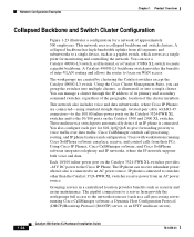
... in full duplex). Figure 1-23 Collapsed Backbone and Switch Cluster Configuration Gigabit servers Cisco CallManager Catalyst 4908G-L3 switch Cisco 2600 router 1 Gbps (2 Gbps full duplex) Catalyst 3500 XL and 2900 XL GigaStack cluster Catalyst 2900 XL, 1900, and 2820 cluster 200 Mbps Fast EtherChannel (400 Mbps full duplex Fast EtherChannel) Catalyst 3524-PWR XL GigaStack cluster IP IP AC power source Workstations...
... in full duplex). Figure 1-23 Collapsed Backbone and Switch Cluster Configuration Gigabit servers Cisco CallManager Catalyst 4908G-L3 switch Cisco 2600 router 1 Gbps (2 Gbps full duplex) Catalyst 3500 XL and 2900 XL GigaStack cluster Catalyst 2900 XL, 1900, and 2820 cluster 200 Mbps Fast EtherChannel (400 Mbps full duplex Fast EtherChannel) Catalyst 3524-PWR XL GigaStack cluster IP IP AC power source Workstations...
Hardware Installation Guide
Page 94
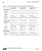
Appendix A Technical Specifications Table A-2 Technical Specifications for the Catalyst 3512, 3524, and 3548 XL Switches Catalyst 3512 XL Catalyst 3524 XL Catalyst 3548 XL Environmental Ranges Operating temperature 32 to 113°F (0 to 45°C) 32 to 113°F (0 to 45°C) 32 to 113°F (0 to 45°C) ....82 x 17.5 in. 1.73 x 15.34 x 17.5 in D x W) (4.45 x 30.02 x 44.45 cm) (4.45 x 30.02 x 44.45 cm) (4.39 x 39.0 x 44.45 cm) Catalyst 3500 Series XL Hardware Installation Guide A-2 78-6456-03
Appendix A Technical Specifications Table A-2 Technical Specifications for the Catalyst 3512, 3524, and 3548 XL Switches Catalyst 3512 XL Catalyst 3524 XL Catalyst 3548 XL Environmental Ranges Operating temperature 32 to 113°F (0 to 45°C) 32 to 113°F (0 to 45°C) 32 to 113°F (0 to 45°C) ....82 x 17.5 in. 1.73 x 15.34 x 17.5 in D x W) (4.45 x 30.02 x 44.45 cm) (4.45 x 30.02 x 44.45 cm) (4.39 x 39.0 x 44.45 cm) Catalyst 3500 Series XL Hardware Installation Guide A-2 78-6456-03

