Hardware Installation Guide
Page 19
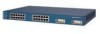
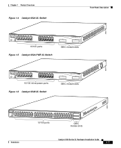
... deployed as servers, routers, and other network devices. A feature specific to the Catalyst 3524-PWR XL switch is its ability to provide inline power to Cisco IP Phones. (Phone adapters are stackable 10/100 Ethernet switches to the Catalyst 3524-PWR XL 10/100 switch ports.) Figure 1-1 shows the switch models in the series, and Table 1-1 and Table 1-2 list their features...
... deployed as servers, routers, and other network devices. A feature specific to the Catalyst 3524-PWR XL switch is its ability to provide inline power to Cisco IP Phones. (Phone adapters are stackable 10/100 Ethernet switches to the Catalyst 3524-PWR XL 10/100 switch ports.) Figure 1-1 shows the switch models in the series, and Table 1-1 and Table 1-2 list their features...
Hardware Installation Guide
Page 23
... on AC input and supplies DC output to the Catalyst 3512, 3524, and 3548 XL switches • Connection for optional Cisco RPS 300 that operates on AC input and supplies DC output to the Catalyst 3524-PWR XL switch Inline Power (Catalyst 3524-PWR XL switch only) • Ability to provide inline power for Cisco IP Phones from all 24 10/100 Ethernet ports...
... on AC input and supplies DC output to the Catalyst 3512, 3524, and 3548 XL switches • Connection for optional Cisco RPS 300 that operates on AC input and supplies DC output to the Catalyst 3524-PWR XL switch Inline Power (Catalyst 3524-PWR XL switch only) • Ability to provide inline power for Cisco IP Phones from all 24 10/100 Ethernet ports...
Hardware Installation Guide
Page 24
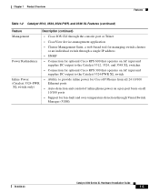
.../100 ports. Front-Panel Description Chapter 1 Product Overview Front-Panel Description The front panel of the Catalyst 3512, 3524, 3524-PWR and 3548 XL switches (Figure 1-3, Figure 1-4, Figure 1-5, and Figure 1-6) have a set of LEDs and a Mode button. (The Catalyst 3548 XL switch has a Mode label that you press.) These front-panel components are described in this section. All...
.../100 ports. Front-Panel Description Chapter 1 Product Overview Front-Panel Description The front panel of the Catalyst 3512, 3524, 3524-PWR and 3548 XL switches (Figure 1-3, Figure 1-4, Figure 1-5, and Figure 1-6) have a set of LEDs and a Mode button. (The Catalyst 3548 XL switch has a Mode label that you press.) These front-panel components are described in this section. All...
Hardware Installation Guide
Page 25
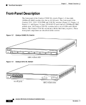
Chapter 1 Product Overview Figure 1-4 Catalyst 3524 XL Switch Front-Panel Description 26237 12 1X 34 56 78 MODE SYSTEM RPS STATUS 2X UTIL DUPLX SPEED 9 10 11 12 11X 12X 13 14 13X 15 16 17 18 19 20 21 22 23 24 23X 14X 24X 10/100 ports Figure 1-5 Catalyst 3524-PWR XL Switch 1 2 GBIC module slots 30291...
Chapter 1 Product Overview Figure 1-4 Catalyst 3524 XL Switch Front-Panel Description 26237 12 1X 34 56 78 MODE SYSTEM RPS STATUS 2X UTIL DUPLX SPEED 9 10 11 12 11X 12X 13 14 13X 15 16 17 18 19 20 21 22 23 24 23X 14X 24X 10/100 ports Figure 1-5 Catalyst 3524-PWR XL Switch 1 2 GBIC module slots 30291...

Hardware Installation Guide
Page 26
...through standard RJ-45 connectors and Category 3, 4, or 5 cabling • 100BaseTX-compatible devices such as high-speed workstations, Cisco IP Phones, servers, hubs, routers, and other switches through , twisted-pair cable. For example, in Figure 1-3, Figure 1-4, Figure 1-5, and Figure 1-6, ports 1 and 2 ... If the connected device also supports autonegotiation, the switch port negotiates the best connection (that is, the fastest line speed that the cable is above port 4, and so on the Catalyst 3512, 3524, 3524-PWR, and 3548 XL switches are grouped in Appendix B, "Connector and Cable ...
...through standard RJ-45 connectors and Category 3, 4, or 5 cabling • 100BaseTX-compatible devices such as high-speed workstations, Cisco IP Phones, servers, hubs, routers, and other switches through , twisted-pair cable. For example, in Figure 1-3, Figure 1-4, Figure 1-5, and Figure 1-6, ports 1 and 2 ... If the connected device also supports autonegotiation, the switch port negotiates the best connection (that is, the fastest line speed that the cable is above port 4, and so on the Catalyst 3512, 3524, 3524-PWR, and 3548 XL switches are grouped in Appendix B, "Connector and Cable ...
Hardware Installation Guide
Page 27
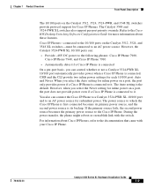
...on a port, the port does not provide power even if a Cisco IP Phone is connected to it . Cisco IP Phones-connected to the 10/100 ports on the Catalyst 3512, 3524, and 3548 XL switches-must be connected to the Cisco IP Phone. However, when you select the Auto setting for redundant ...Description The 10/100 ports on the Catalyst 3512, 3524, 3524-PWR, and 3548 XL switches provide protocol support for each 10/100 port: Auto and Never. The Catalyst 3548 and 3524-PWR XL switches also support per -port basis, you can connect the Cisco IP Phone to a Catalyst 3524-PWR XL 10/100 port and to an ...
...on a port, the port does not provide power even if a Cisco IP Phone is connected to it . Cisco IP Phones-connected to the 10/100 ports on the Catalyst 3512, 3524, and 3548 XL switches-must be connected to the Cisco IP Phone. However, when you select the Auto setting for redundant ...Description The 10/100 ports on the Catalyst 3512, 3524, 3524-PWR, and 3548 XL switches provide protocol support for each 10/100 port: Auto and Never. The Catalyst 3548 and 3524-PWR XL switches also support per -port basis, you can connect the Cisco IP Phone to a Catalyst 3524-PWR XL 10/100 port and to an ...
Hardware Installation Guide
Page 28
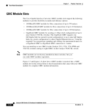
...Cisco proprietary signaling and cabling, the maximum distance for a GigaStack GBIC-to eight GBICs in the Catalyst 3512, 3524, 3524-PWR and 3548 XL switches and up to -GigaStack GBIC connection is inserted into a GBIC module slot on these switches, but you can install up to nine Catalyst 3500 XL switches... module for creating a 1-Gbps stack configuration of up to two GBICs in the Catalyst 3508G XL switch. Front-Panel Description Chapter 1 Product Overview GBIC Module Slots The Cisco Gigabit Interface Converter (GBIC) module slots support the following modules to provide flexibility in...
...Cisco proprietary signaling and cabling, the maximum distance for a GigaStack GBIC-to eight GBICs in the Catalyst 3512, 3524, 3524-PWR and 3548 XL switches and up to -GigaStack GBIC connection is inserted into a GBIC module slot on these switches, but you can install up to nine Catalyst 3500 XL switches... module for creating a 1-Gbps stack configuration of up to two GBICs in the Catalyst 3508G XL switch. Front-Panel Description Chapter 1 Product Overview GBIC Module Slots The Cisco Gigabit Interface Converter (GBIC) module slots support the following modules to provide flexibility in...
Hardware Installation Guide
Page 34
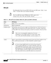
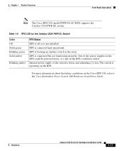
... on the bottom of the power supplies in the RPS could have failed. The LEDs display correctly for the Catalyst 3508, 3512, 3524, and 3548 XL Switches Color Off Solid green Blinking green RPS Status RPS is off or is not installed. Table 1-4 RPS LED for ... RPS with a revision level lower than Z3 with a Catalyst 3508G XL or a Catalyst 3548 XL switch, the switch RPS LED might display amber (normally indicating an RPS malfunction) even when the RPS is not a recommended configuration. Note The Cisco RPS 600 (model PWR600-AC-RPS) supports the Catalyst 3512, 3524, 3548, and 3508 XL switches.
... on the bottom of the power supplies in the RPS could have failed. The LEDs display correctly for the Catalyst 3508, 3512, 3524, and 3548 XL Switches Color Off Solid green Blinking green RPS Status RPS is off or is not installed. Table 1-4 RPS LED for ... RPS with a revision level lower than Z3 with a Catalyst 3508G XL or a Catalyst 3548 XL switch, the switch RPS LED might display amber (normally indicating an RPS malfunction) even when the RPS is not a recommended configuration. Note The Cisco RPS 600 (model PWR600-AC-RPS) supports the Catalyst 3512, 3524, 3548, and 3508 XL switches.
Hardware Installation Guide
Page 35
... Catalyst 3500 Series XL Hardware Installation Guide 1-17 RPS is not installed. One of the switch is down , or a fan on the RPS could be powered down , and redundancy is connected and operational. RPS is lost. Chapter 1 Product Overview Front-Panel Description Note The Cisco RPS 300 (model PWR300-AC-RPS) supports the Catalyst 3524-PWR XL switch...
... Catalyst 3500 Series XL Hardware Installation Guide 1-17 RPS is not installed. One of the switch is down , or a fan on the RPS could be powered down , and redundancy is connected and operational. RPS is lost. Chapter 1 Product Overview Front-Panel Description Note The Cisco RPS 300 (model PWR300-AC-RPS) supports the Catalyst 3524-PWR XL switch...
Hardware Installation Guide
Page 37
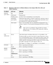
...LED to 30 seconds as excessive collisions, CRC errors, and alignment and jabber errors are green, the switch is operating at 1000 Mbps. 78-6456-03 Catalyst 3500 Series XL Hardware Installation Guide 1-19 Port is using less than 50 percent of the right-most LED is amber,...SPEED (speed) Green Off Green 10/100 ports Off Green 1000BaseX ports Off Green The LEDs display backplane utilization on the Catalyst 3508, 3512, 3524, and 3548 XL Switches Port Mode STATUS (port status) LED Color Off Solid green Flashing green Alternating green-amber Solid amber Meaning No link. ...
...LED to 30 seconds as excessive collisions, CRC errors, and alignment and jabber errors are green, the switch is operating at 1000 Mbps. 78-6456-03 Catalyst 3500 Series XL Hardware Installation Guide 1-19 Port is using less than 50 percent of the right-most LED is amber,...SPEED (speed) Green Off Green 10/100 ports Off Green 1000BaseX ports Off Green The LEDs display backplane utilization on the Catalyst 3508, 3512, 3524, and 3548 XL Switches Port Mode STATUS (port status) LED Color Off Solid green Flashing green Alternating green-amber Solid amber Meaning No link. ...
Hardware Installation Guide
Page 38
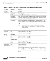
... a port is connected to 30 seconds as excessive collisions, CRC errors, and alignment and jabber errors are monitored for possible loops. If the Cisco IP Phone is receiving power from an AC power source, the port LED is off . Link present. DUPLEX Off Green SPEED (speed) 10...management or an address violation or was blocked by Spanning Tree Protocol (STP). Port is operating at 10 Mbps. Port is on the Catalyst 3524-PWR XL Switch Port Mode STATUS (port status) LED Color Off Solid green Flashing green Alternating green-amber Solid amber Meaning No link. Error frames ...
... a port is connected to 30 seconds as excessive collisions, CRC errors, and alignment and jabber errors are monitored for possible loops. If the Cisco IP Phone is receiving power from an AC power source, the port LED is off . Link present. DUPLEX Off Green SPEED (speed) 10...management or an address violation or was blocked by Spanning Tree Protocol (STP). Port is operating at 10 Mbps. Port is on the Catalyst 3524-PWR XL Switch Port Mode STATUS (port status) LED Color Off Solid green Flashing green Alternating green-amber Solid amber Meaning No link. Error frames ...
Hardware Installation Guide
Page 39
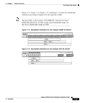
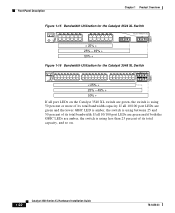
... usage, use the Device Bandwidth Graph on the Catalyst 3524-PWR XL switch do not show bandwidth utilization. Figure 1-13 Bandwidth Utilization for the Catalyst 3508G XL Switch 1 MODE SYSTEM RPS STATUS UTIL DUPLX SPEED 2 3 4 5 Catalyst 3500 XL 6 7 8 < 25% 25% - 49% + 50% + Figure 1-14 Bandwidth Utilization for the Catalyst 3512 XL Switch MODE SYSTEM RPS STATUS UTIL DUPLX SPEED 12 1X 34...
... usage, use the Device Bandwidth Graph on the Catalyst 3524-PWR XL switch do not show bandwidth utilization. Figure 1-13 Bandwidth Utilization for the Catalyst 3508G XL Switch 1 MODE SYSTEM RPS STATUS UTIL DUPLX SPEED 2 3 4 5 Catalyst 3500 XL 6 7 8 < 25% 25% - 49% + 50% + Figure 1-14 Bandwidth Utilization for the Catalyst 3512 XL Switch MODE SYSTEM RPS STATUS UTIL DUPLX SPEED 12 1X 34...
Hardware Installation Guide
Page 40
... using between 25 and 50 percent of its total bandwidth capacity. Front-Panel Description Chapter 1 Product Overview 22007 Figure 1-15 Bandwidth Utilization for the Catalyst 3524 XL Switch MODE SYSTEM RPS STATUS UTIL DUPLX SPEED 12 1X 34 56 78 9 10 11 12 11X 2X 12X 13 14 15 16 13X 17 18 ...19 20 21 22 23 24 15X 14X 16X < 25% + 25% - 49% + 50% + Catalyst 3500 XL 1 2 Figure 1-16 Bandwidth Utilization for the Catalyst 3548 XL Switch 28366 SYSTEM RPS STATUS UTIL DUPLX SPEED MODE 12 1X 3 24 56 78 9 10 11 12 13 14 15 16 15X...
... using between 25 and 50 percent of its total bandwidth capacity. Front-Panel Description Chapter 1 Product Overview 22007 Figure 1-15 Bandwidth Utilization for the Catalyst 3524 XL Switch MODE SYSTEM RPS STATUS UTIL DUPLX SPEED 12 1X 34 56 78 9 10 11 12 11X 2X 12X 13 14 15 16 13X 17 18 ...19 20 21 22 23 24 15X 14X 16X < 25% + 25% - 49% + 50% + Catalyst 3500 XL 1 2 Figure 1-16 Bandwidth Utilization for the Catalyst 3548 XL Switch 28366 SYSTEM RPS STATUS UTIL DUPLX SPEED MODE 12 1X 3 24 56 78 9 10 11 12 13 14 15 16 15X...
Hardware Installation Guide
Page 41
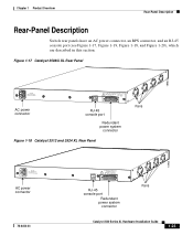
...Rear-Panel Description Rear-Panel Description Switch rear panels have an AC power connector, an RPS connector, and an RJ-45 console port (see Figure 1-17, Figure 1-19, Figure 1-18, and Figure 1-20), which are described in this section. Figure 1-17 Catalyst 3508G XL Rear Panel 18963 RATING 100-...IFNOMRARNEUMAOL.T+E3P.3OVW***E@R1S4UAP, PLY DC INPUT +12V***@3A AC power connector RJ-45 console port Redundant power system connector Figure 1-18 Catalyst 3512 and 3524 XL Rear Panel Fans 18964 RATING 100-127/200-240V~ 1.0A/0.5A 50-60HZ AC power connector 78-6456-03 CONSOLE DC INPUTS FOR...
...Rear-Panel Description Rear-Panel Description Switch rear panels have an AC power connector, an RPS connector, and an RJ-45 console port (see Figure 1-17, Figure 1-19, Figure 1-18, and Figure 1-20), which are described in this section. Figure 1-17 Catalyst 3508G XL Rear Panel 18963 RATING 100-...IFNOMRARNEUMAOL.T+E3P.3OVW***E@R1S4UAP, PLY DC INPUT +12V***@3A AC power connector RJ-45 console port Redundant power system connector Figure 1-18 Catalyst 3512 and 3524 XL Rear Panel Fans 18964 RATING 100-127/200-240V~ 1.0A/0.5A 50-60HZ AC power connector 78-6456-03 CONSOLE DC INPUTS FOR...

Hardware Installation Guide
Page 43
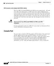
... supports input voltages between 100 and 240 VAC. Cisco RPS Connector Specific Cisco RPS models support specific Catalyst 3500 XL switches: • Cisco RPS 600 (model PWR600-AC-RPS)-Supports the Catalyst 3512, 3524, 3548, and 3508 XL switches • Cisco RPS 300 (model PWR300-AC-RPS)-Supports the Catalyst 3524-PWR XL switch RPS Connector on the Cisco RPS 600, refer to the RPS receptacle...
... supports input voltages between 100 and 240 VAC. Cisco RPS Connector Specific Cisco RPS models support specific Catalyst 3500 XL switches: • Cisco RPS 600 (model PWR600-AC-RPS)-Supports the Catalyst 3512, 3524, 3548, and 3508 XL switches • Cisco RPS 300 (model PWR300-AC-RPS)-Supports the Catalyst 3524-PWR XL switch RPS Connector on the Cisco RPS 600, refer to the RPS receptacle...
Hardware Installation Guide
Page 44
... port and the supplied rollover cable and DB-9 adapter. For console port and adapter pinout information, see the "Cable and Adapter Specifications" section on the Catalyst 3524-PWR XL Switch The Cisco RPS 300 (model PWR300-AC-RPS) has two output levels: -48V and 12V with a total output power of 300W. For more than one...
... port and the supplied rollover cable and DB-9 adapter. For console port and adapter pinout information, see the "Cable and Adapter Specifications" section on the Catalyst 3524-PWR XL Switch The Cisco RPS 300 (model PWR300-AC-RPS) has two output levels: -48V and 12V with a total output power of 300W. For more than one...
Hardware Installation Guide
Page 52
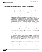
... features and configuration. You can group the switches into a single cluster. A Catalyst 4908G-L3 backbone switch provides the benefits of inter-VLAN routing and allows the router to focus on the Catalyst 3524-PWR XL switches provides -48V DC power to the Cisco IP Phone. You can receive redundant power ...when it also is connected. These multiservice switch ports automatically detect if an IP phone is connected to an...
... features and configuration. You can group the switches into a single cluster. A Catalyst 4908G-L3 backbone switch provides the benefits of inter-VLAN routing and allows the router to focus on the Catalyst 3524-PWR XL switches provides -48V DC power to the Cisco IP Phone. You can receive redundant power ...when it also is connected. These multiservice switch ports automatically detect if an IP phone is connected to an...

Hardware Installation Guide
Page 53
... in full duplex). Figure 1-23 Collapsed Backbone and Switch Cluster Configuration Gigabit servers Cisco CallManager Catalyst 4908G-L3 switch Cisco 2600 router 1 Gbps (2 Gbps full duplex) Catalyst 3500 XL and 2900 XL GigaStack cluster Catalyst 2900 XL, 1900, and 2820 cluster 200 Mbps Fast EtherChannel (400 Mbps full duplex Fast EtherChannel) Catalyst 3524-PWR XL GigaStack cluster IP IP AC power source Workstations...
... in full duplex). Figure 1-23 Collapsed Backbone and Switch Cluster Configuration Gigabit servers Cisco CallManager Catalyst 4908G-L3 switch Cisco 2600 router 1 Gbps (2 Gbps full duplex) Catalyst 3500 XL and 2900 XL GigaStack cluster Catalyst 2900 XL, 1900, and 2820 cluster 200 Mbps Fast EtherChannel (400 Mbps full duplex Fast EtherChannel) Catalyst 3524-PWR XL GigaStack cluster IP IP AC power source Workstations...
Hardware Installation Guide
Page 60
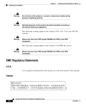
... (model PWR600-AC-RPS) to the RPS receptacle. Warning Ultimate disposal of this manual. 15456 Catalyst 3500 Series XL Hardware Installation Guide 2-4 78-6456-03 The following warning applies to the Catalyst 3524-PWR XL switch: Warning Attach only the Cisco RPS (model PWR300-AC-RPS) to the RPS receptacle. Preparing for this product is in the...
... (model PWR600-AC-RPS) to the RPS receptacle. Warning Ultimate disposal of this manual. 15456 Catalyst 3500 Series XL Hardware Installation Guide 2-4 78-6456-03 The following warning applies to the Catalyst 3524-PWR XL switch: Warning Attach only the Cisco RPS (model PWR300-AC-RPS) to the RPS receptacle. Preparing for this product is in the...
Hardware Installation Guide
Page 91
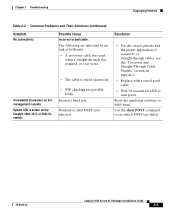
... 3-2 Common Problems and Their Solutions (continued) Symptom No connectivity. straight-through was used when a straight-through cables, see which POST test failed. 78-6456-03 Catalyst 3500 Series XL Hardware Installation Guide 3-5 Unreadable characters on the Catalyst 3508, 3512, or 3524 XL switch.
... 3-2 Common Problems and Their Solutions (continued) Symptom No connectivity. straight-through was used when a straight-through cables, see which POST test failed. 78-6456-03 Catalyst 3500 Series XL Hardware Installation Guide 3-5 Unreadable characters on the Catalyst 3508, 3512, or 3524 XL switch.


