Hardware Installation Guide
Page 2
..., FITNESS FOR A PARTICULAR PURPOSE AND NONINFRINGEMENT OR ARISING FROM A COURSE OF DEALING, USAGE, OR TRADE PRACTICE. and Aironet, ASIST, BPX, Catalyst, Cisco, Cisco The Cisco implementation of its peripheral devices. This equipment has been tested and found to comply with Me, CCDA, CCDE, CCDP, CCIE, CCNA, CCNP,... has been tested and found to comply with the limits for a Class B digital device in accordance with the specifications in accordance with FCC requirements for a Class A digital device, pursuant to radio or television communications at their own expense. These...
..., FITNESS FOR A PARTICULAR PURPOSE AND NONINFRINGEMENT OR ARISING FROM A COURSE OF DEALING, USAGE, OR TRADE PRACTICE. and Aironet, ASIST, BPX, Catalyst, Cisco, Cisco The Cisco implementation of its peripheral devices. This equipment has been tested and found to comply with Me, CCDA, CCDE, CCDP, CCIE, CCNA, CCNP,... has been tested and found to comply with the limits for a Class B digital device in accordance with the specifications in accordance with FCC requirements for a Class A digital device, pursuant to radio or television communications at their own expense. These...
Hardware Installation Guide
Page 7
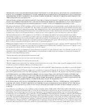
...Assigning Switch Information 2-24 Using the Setup Program 2-24 Using BOOTP 2-28 Default Configuration Settings 2-29 Where to Go Next 2-30 Troubleshooting 3-1 Understanding POST Results 3-2 Diagnosing Problems 3-3 Technical Specifications A-1 Connector and Cable Specifications B-1 Connector Specifications ...B-1 10/100 Ports B-1 1000BaseX Ports B-2 Gigastack Port B-3 Console Port B-3 Cable and Adapter Specifications B-4 Crossover and Straight-Through Cable Pinouts B-4 78-6456-03 Catalyst 3500 Series ...
...Assigning Switch Information 2-24 Using the Setup Program 2-24 Using BOOTP 2-28 Default Configuration Settings 2-29 Where to Go Next 2-30 Troubleshooting 3-1 Understanding POST Results 3-2 Diagnosing Problems 3-3 Technical Specifications A-1 Connector and Cable Specifications B-1 Connector Specifications ...B-1 10/100 Ports B-1 1000BaseX Ports B-2 Gigastack Port B-3 Console Port B-3 Cable and Adapter Specifications B-4 Crossover and Straight-Through Cable Pinouts B-4 78-6456-03 Catalyst 3500 Series ...
Hardware Installation Guide
Page 10
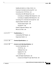
...in this guide. Appendix B, "Connector and Cable Specifications," describes the connectors, cables, and adapters that might arise when you are installing the switch. Chapter 2, "Installing and Starting Up the Switch," contains the procedures for the switches and the regulatory agency approvals. Examples use these...8226; Information you supply values are in italic. Catalyst 3500 Series XL Hardware Installation Guide x 78-6456-03 Organization Preface Organization This guide is organized into the following conventions to the switch. It also describes how to identify and resolve ...
...in this guide. Appendix B, "Connector and Cable Specifications," describes the connectors, cables, and adapters that might arise when you are installing the switch. Chapter 2, "Installing and Starting Up the Switch," contains the procedures for the switches and the regulatory agency approvals. Examples use these...8226; Information you supply values are in italic. Catalyst 3500 Series XL Hardware Installation Guide x 78-6456-03 Organization Preface Organization This guide is organized into the following conventions to the switch. It also describes how to identify and resolve ...
Hardware Installation Guide
Page 15
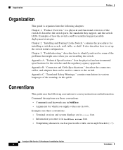
...networked services that provides immediate, open access to Cisco. Through CCO, you will find information about Cisco and our networking solutions, services, and programs. In addition, you can resolve technical issues with Cisco. 78-6456-03 Catalyst 3500 Series XL Hardware Installation Guide xv Customers ...stamped response card included in many printed docs, or by calling Cisco's corporate headquarters (California, USA) at 408 526-4000 or, in the world. CCO's broad range of an order and view benefits specific to -use the Technical Assistance Center. Registered users may order products...
...networked services that provides immediate, open access to Cisco. Through CCO, you will find information about Cisco and our networking solutions, services, and programs. In addition, you can resolve technical issues with Cisco. 78-6456-03 Catalyst 3500 Series XL Hardware Installation Guide xv Customers ...stamped response card included in many printed docs, or by calling Cisco's corporate headquarters (California, USA) at 408 526-4000 or, in the world. CCO's broad range of an order and view benefits specific to -use the Technical Assistance Center. Registered users may order products...
Hardware Installation Guide
Page 19
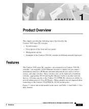
... as servers, routers, and other network devices. A feature specific to the Catalyst 3524-PWR XL switch is its ability to provide inline power to Cisco IP Phones. (Phone adapters are stackable 10/100 Ethernet switches to the Catalyst 3524-PWR XL 10/100 switch ports.) Figure 1-1 shows the switch models in the series, and Table 1-1 and Table 1-2 list...
... as servers, routers, and other network devices. A feature specific to the Catalyst 3524-PWR XL switch is its ability to provide inline power to Cisco IP Phones. (Phone adapters are stackable 10/100 Ethernet switches to the Catalyst 3524-PWR XL 10/100 switch ports.) Figure 1-1 shows the switch models in the series, and Table 1-1 and Table 1-2 list...

Hardware Installation Guide
Page 26
... cable is above port 4, and so on the Catalyst 3512, 3524, 3524-PWR, and 3548 XL switches are the left-most pair. Catalyst 3500 Series XL Hardware Installation Guide 1-8 78-6456-...4, or 5 cabling • 100BaseTX-compatible devices such as high-speed workstations, Cisco IP Phones, servers, hubs, routers, and other switches through , twisted-pair cable. These ports also can connect, up to a ... in Appendix B, "Connector and Cable Specifications." Front-Panel Description Chapter 1 Product Overview 10/100 Ports The 10/100 ports on . The 10/100 switch ports can be sure that both devices...
... cable is above port 4, and so on the Catalyst 3512, 3524, 3524-PWR, and 3548 XL switches are the left-most pair. Catalyst 3500 Series XL Hardware Installation Guide 1-8 78-6456-...4, or 5 cabling • 100BaseTX-compatible devices such as high-speed workstations, Cisco IP Phones, servers, hubs, routers, and other switches through , twisted-pair cable. These ports also can connect, up to a ... in Appendix B, "Connector and Cable Specifications." Front-Panel Description Chapter 1 Product Overview 10/100 Ports The 10/100 ports on . The 10/100 switch ports can be sure that both devices...

Hardware Installation Guide
Page 43
... through the Cisco RPS. Cisco RPS Connector Specific Cisco RPS models support specific Catalyst 3500 XL switches: • Cisco RPS 600 (model PWR600-AC-RPS)-Supports the Catalyst 3512, 3524, 3548, and 3508 XL switches • Cisco RPS 300 (model PWR300-AC-RPS)-Supports the Catalyst 3524-PWR XL switch RPS Connector on the Catalyst 3508, 3512, 3524, and 3548 XL Switches The Cisco RPS 600...
... through the Cisco RPS. Cisco RPS Connector Specific Cisco RPS models support specific Catalyst 3500 XL switches: • Cisco RPS 600 (model PWR600-AC-RPS)-Supports the Catalyst 3512, 3524, 3548, and 3508 XL switches • Cisco RPS 300 (model PWR300-AC-RPS)-Supports the Catalyst 3524-PWR XL switch RPS Connector on the Catalyst 3508, 3512, 3524, and 3548 XL Switches The Cisco RPS 600...
Hardware Installation Guide
Page 44
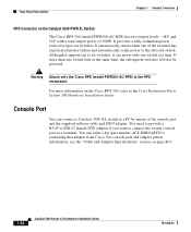
... port to the RPS receptacle. For console port and adapter pinout information, see the "Cable and Adapter Specifications" section on the Catalyst 3524-PWR XL Switch The Cisco RPS 300 (model PWR300-AC-RPS) has two output levels: -48V and 12V with a total output power of the console port and the supplied rollover ...
... port to the RPS receptacle. For console port and adapter pinout information, see the "Cable and Adapter Specifications" section on the Catalyst 3524-PWR XL Switch The Cisco RPS 300 (model PWR300-AC-RPS) has two output levels: -48V and 12V with a total output power of the console port and the supplied rollover ...
Hardware Installation Guide
Page 61
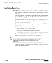
...2 Installing and Starting Up the Switch Preparing for unrestricted cabling. - Note If the switch is installed in Appendix A, "Technical Specifications." • Clearance to 1 meter. For specific cable lengths, refer to the ... When determining where to place the switch, be sure to observe these guidelines: • For 10/100 ports, cable lengths from the switch to connected devices are up to 100...; Airflow around the switch and through the vents is unrestricted. • Temperature around it might be easily read. - Access to the documents that - For specific cable lengths, refer to...
...2 Installing and Starting Up the Switch Preparing for unrestricted cabling. - Note If the switch is installed in Appendix A, "Technical Specifications." • Clearance to 1 meter. For specific cable lengths, refer to the ... When determining where to place the switch, be sure to observe these guidelines: • For 10/100 ports, cable lengths from the switch to connected devices are up to 100...; Airflow around the switch and through the vents is unrestricted. • Temperature around it might be easily read. - Access to the documents that - For specific cable lengths, refer to...
Hardware Installation Guide
Page 78
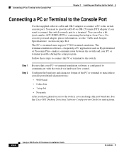
...supplied rollover cable and DB-9 adapter to connect a PC to communicate with the switch via hardware flow control. or terminal-emulation software is configured to the switch console port. The terminal-emulation software-frequently a PC application such as Hyperterminal ... the switch: Step 1 Step 2 Be sure that adapter from Cisco. See the Cisco IOS Desktop Switching Software Configuration Guide for instructions. 2-22 Catalyst 3500 Series XL Hardware Installation Guide 78-6456-03 For console port and adapter pinout information, see the "Cable and Adapter Specifications" section...
...supplied rollover cable and DB-9 adapter to connect a PC to communicate with the switch via hardware flow control. or terminal-emulation software is configured to the switch console port. The terminal-emulation software-frequently a PC application such as Hyperterminal ... the switch: Step 1 Step 2 Be sure that adapter from Cisco. See the Cisco IOS Desktop Switching Software Configuration Guide for instructions. 2-22 Catalyst 3500 Series XL Hardware Installation Guide 78-6456-03 For console port and adapter pinout information, see the "Cable and Adapter Specifications" section...
Hardware Installation Guide
Page 81
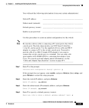
...connect a PC to restart the setup program. You need the following information from Cisco. Step 1 Step 2 Step 3 Step 4 Enter Y at the prompt: Continue with configuration dialog? [yes/no parity. Enter the switch IP address, and press Return: Enter IP address: ip_address Enter the subnet mask... "Cable and Adapter Specifications" section on page B-4. Chapter 2 Installing and Starting Up the Switch Assigning Switch Information You will need to provide a RJ-45-to-DB-25 female DTE adapter if you like to enter a default gateway address? [yes]: y 78-6456-03 Catalyst 3500 Series XL Hardware...
...connect a PC to restart the setup program. You need the following information from Cisco. Step 1 Step 2 Step 3 Step 4 Enter Y at the prompt: Continue with configuration dialog? [yes/no parity. Enter the switch IP address, and press Return: Enter IP address: ip_address Enter the subnet mask... "Cable and Adapter Specifications" section on page B-4. Chapter 2 Installing and Starting Up the Switch Assigning Switch Information You will need to provide a RJ-45-to-DB-25 female DTE adapter if you like to enter a default gateway address? [yes]: y 78-6456-03 Catalyst 3500 Series XL Hardware...
Hardware Installation Guide
Page 93
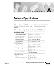
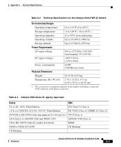
...-6456-03 Table A-1, Table A-2, and Table A-3, list the technical specifications for the Catalyst 3508G XL Switch Environmental Ranges Operating temperature Storage temperature Operating humidity Operating altitude Storage altitude Power Requirements AC input voltage DC input voltages Power consumption ...@14A, +12V @3A 82.2W 280 Btus per hour 12 lb (5.45 kg) 1.75 x 16 x 17.5 in. (4.45 x 40.46 x 44.45 cm) Catalyst 3500 Series XL Hardware Installation Guide A-1 Table A-1 Technical Specifications for the Catalyst 3500 series XL switches. Table A-4 lists the regulatory agency approvals.
...-6456-03 Table A-1, Table A-2, and Table A-3, list the technical specifications for the Catalyst 3508G XL Switch Environmental Ranges Operating temperature Storage temperature Operating humidity Operating altitude Storage altitude Power Requirements AC input voltage DC input voltages Power consumption ...@14A, +12V @3A 82.2W 280 Btus per hour 12 lb (5.45 kg) 1.75 x 16 x 17.5 in. (4.45 x 40.46 x 44.45 cm) Catalyst 3500 Series XL Hardware Installation Guide A-1 Table A-1 Technical Specifications for the Catalyst 3500 series XL switches. Table A-4 lists the regulatory agency approvals.
Hardware Installation Guide
Page 94
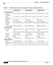
Appendix A Technical Specifications Table A-2 Technical Specifications for the Catalyst 3512, 3524, and 3548 XL Switches Catalyst 3512 XL Catalyst 3524 XL Catalyst 3548 XL Environmental Ranges Operating temperature 32 to 113°F (0 to 45°C) 32 to 113°F (0 to 45°C) 32 to 113°F (0 to ....82 x 17.5 in. 1.73 x 15.34 x 17.5 in D x W) (4.45 x 30.02 x 44.45 cm) (4.45 x 30.02 x 44.45 cm) (4.39 x 39.0 x 44.45 cm) Catalyst 3500 Series XL Hardware Installation Guide A-2 78-6456-03
Appendix A Technical Specifications Table A-2 Technical Specifications for the Catalyst 3512, 3524, and 3548 XL Switches Catalyst 3512 XL Catalyst 3524 XL Catalyst 3548 XL Environmental Ranges Operating temperature 32 to 113°F (0 to 45°C) 32 to 113°F (0 to 45°C) 32 to 113°F (0 to ....82 x 17.5 in. 1.73 x 15.34 x 17.5 in D x W) (4.45 x 30.02 x 44.45 cm) (4.45 x 30.02 x 44.45 cm) (4.39 x 39.0 x 44.45 cm) Catalyst 3500 Series XL Hardware Installation Guide A-2 78-6456-03
Hardware Installation Guide
Page 95
... power consumption depends on the number of IP phones connected. 325W represents 24 IP phones connected. Appendix A Technical Specifications Table A-3 Technical Specifications for the Catalyst 3524-PWR XL Switch Environmental Ranges Operating temperature 32 to 113°F (0 to 45°C) Storage temperature -4 to 149°F (-10...) 50 to NOM-019-SCFI CE Marking CE Marking 78-6456-03 Catalyst 3500 Series XL Hardware Installation Guide A-3 Table A-4 Catalyst 3500 Series XL Agency Approvals Safety EMC UL to UL 1950, Third Edition FCC Part 15 Class A c-UL to CAN/CSA 22.2 No. ...
... power consumption depends on the number of IP phones connected. 325W represents 24 IP phones connected. Appendix A Technical Specifications Table A-3 Technical Specifications for the Catalyst 3524-PWR XL Switch Environmental Ranges Operating temperature 32 to 113°F (0 to 45°C) Storage temperature -4 to 149°F (-10...) 50 to NOM-019-SCFI CE Marking CE Marking 78-6456-03 Catalyst 3500 Series XL Hardware Installation Guide A-3 Table A-4 Catalyst 3500 Series XL Agency Approvals Safety EMC UL to UL 1950, Third Edition FCC Part 15 Class A c-UL to CAN/CSA 22.2 No. ...

Hardware Installation Guide
Page 96
Appendix A Technical Specifications Catalyst 3500 Series XL Hardware Installation Guide A-4 78-6456-03
Appendix A Technical Specifications Catalyst 3500 Series XL Hardware Installation Guide A-4 78-6456-03
Hardware Installation Guide
Page 97
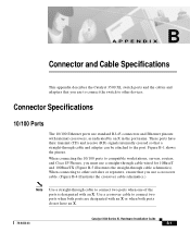
.../100 ports to compatible workstations, servers, routers, and Cisco IP Phones, you must use standard RJ-45 connectors and Ethernet pinouts with internal crossovers, as indicated by an X in the port name. APPENDIX B Connector and Cable Specifications This appendix describes the Catalyst 3500 XL switch ports and the cables and adapters that you use...
.../100 ports to compatible workstations, servers, routers, and Cisco IP Phones, you must use standard RJ-45 connectors and Ethernet pinouts with internal crossovers, as indicated by an X in the port name. APPENDIX B Connector and Cable Specifications This appendix describes the Catalyst 3500 XL switch ports and the cables and adapters that you use...
Hardware Installation Guide
Page 98
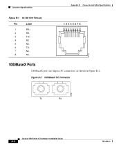
Connector Specifications Appendix B Connector and Cable Specifications Figure B-1 10/100 Port Pinouts Pin Label 1 RD+ 2 RD- 3 TD+ 4 NC 5 NC 6 TD- 7 NC 8 NC 12345678 H5318 1000BaseX Ports 1000BaseX ports use duplex SC connectors, as shown in Figure B-2. Figure B-2 1000BaseX SC Connector H8707 Tx Rx Catalyst 3500 Series XL Hardware Installation Guide B-2 78-6456-03
Connector Specifications Appendix B Connector and Cable Specifications Figure B-1 10/100 Port Pinouts Pin Label 1 RD+ 2 RD- 3 TD+ 4 NC 5 NC 6 TD- 7 NC 8 NC 12345678 H5318 1000BaseX Ports 1000BaseX ports use duplex SC connectors, as shown in Figure B-2. Figure B-2 1000BaseX SC Connector H8707 Tx Rx Catalyst 3500 Series XL Hardware Installation Guide B-2 78-6456-03
Hardware Installation Guide
Page 99
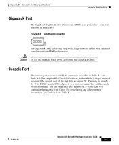
... if you want to connect the switch console port to -RJ-45 rollover cable and DB-9 adapter are proprietary, high-data-rate cables with the GigaStack GBIC. Appendix B Connector and Cable Specifications Connector Specifications Gigastack Port The GigaStack Gigabit Interface ...Converter (GBIC) uses proprietary connectors, as shown in Table B-1 and Table B-2. For console port and adapter pinout information, see Table B-1 and Table B-2. 78-6456-03 Catalyst 3500 Series XL Hardware...
... if you want to connect the switch console port to -RJ-45 rollover cable and DB-9 adapter are proprietary, high-data-rate cables with the GigaStack GBIC. Appendix B Connector and Cable Specifications Connector Specifications Gigastack Port The GigaStack Gigabit Interface ...Converter (GBIC) uses proprietary connectors, as shown in Table B-1 and Table B-2. For console port and adapter pinout information, see Table B-1 and Table B-2. 78-6456-03 Catalyst 3500 Series XL Hardware...
Hardware Installation Guide
Page 100
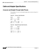
Figure B-4 Crossover Cable Schematic Switch 3 TD+ 6 TD- Switch 3 RD+ 6 RD- Switch 3 TD+ 6 TD- Figure B-5 Straight-Through Cable Schematic Switch 3 TD+ 6 TD- H5578 1 RD+ 2 RD- 1 TD+ 2 TD- Catalyst 3500 Series XL Hardware Installation Guide B-4 78-6456-03 Cable and Adapter Specifications Appendix B Connector and Cable Specifications Cable and Adapter Specifications Crossover and Straight-Through Cable Pinouts The schematics of crossover and straight-through cables are shown in Figure B-4 and Figure B-5. H5579 1 RD+ 2 RD- 1 RD+ 2 RD-
Figure B-4 Crossover Cable Schematic Switch 3 TD+ 6 TD- Switch 3 RD+ 6 RD- Switch 3 TD+ 6 TD- Figure B-5 Straight-Through Cable Schematic Switch 3 TD+ 6 TD- H5578 1 RD+ 2 RD- 1 TD+ 2 TD- Catalyst 3500 Series XL Hardware Installation Guide B-4 78-6456-03 Cable and Adapter Specifications Appendix B Connector and Cable Specifications Cable and Adapter Specifications Crossover and Straight-Through Cable Pinouts The schematics of crossover and straight-through cables are shown in Figure B-4 and Figure B-5. H5579 1 RD+ 2 RD- 1 RD+ 2 RD-
Hardware Installation Guide
Page 101
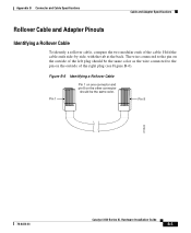
Appendix B Connector and Cable Specifications Cable and Adapter Specifications Rollover Cable and Adapter Pinouts Identifying a Rollover Cable To identify a rollover cable, compare the two modular ends of the left plug should be the same ... the outside of the right plug (see Figure B-6). The wire connected to the pin on the outside of the cable. Pin 8 H10632 78-6456-03 Catalyst 3500 Series XL Hardware Installation Guide B-5
Appendix B Connector and Cable Specifications Cable and Adapter Specifications Rollover Cable and Adapter Pinouts Identifying a Rollover Cable To identify a rollover cable, compare the two modular ends of the left plug should be the same ... the outside of the right plug (see Figure B-6). The wire connected to the pin on the outside of the cable. Pin 8 H10632 78-6456-03 Catalyst 3500 Series XL Hardware Installation Guide B-5