Hardware Installation Guide
Page 7
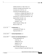
... a PC or Terminal to the Console Port 2-22 Assigning Switch Information 2-24 Using the Setup Program 2-24 Using BOOTP 2-28 Default Configuration Settings 2-29 Where to Go... Next 2-30 Troubleshooting 3-1 Understanding POST Results 3-2 Diagnosing Problems 3-3 Technical Specifications A-1 Connector and Cable Specifications B-1 Connector Specifications B-1 10/100 Ports B-1 1000BaseX Ports B-2 Gigastack Port B-3 Console Port B-3 Cable and Adapter Specifications B-4 Crossover and Straight-Through Cable Pinouts B-4 78-6456-03 Catalyst...
... a PC or Terminal to the Console Port 2-22 Assigning Switch Information 2-24 Using the Setup Program 2-24 Using BOOTP 2-28 Default Configuration Settings 2-29 Where to Go... Next 2-30 Troubleshooting 3-1 Understanding POST Results 3-2 Diagnosing Problems 3-3 Technical Specifications A-1 Connector and Cable Specifications B-1 Connector Specifications B-1 10/100 Ports B-1 1000BaseX Ports B-2 Gigastack Port B-3 Console Port B-3 Cable and Adapter Specifications B-4 Crossover and Straight-Through Cable Pinouts B-4 78-6456-03 Catalyst...

Hardware Installation Guide
Page 20
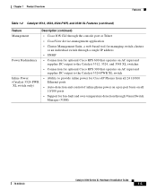
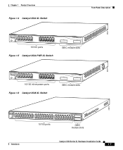
Features Chapter 1 Product Overview Figure 1-1 Catalyst 3500 Series XL Switches Switch Description WS-C3508G-XL 8 GBIC1-based gigabit module slots 1 SYSTEM 2 3 RPS 4 5 MODE STATUS UTIL DUPLX SPEED 6 7 8 WS-C3512-XL 12 autosensing10/100 Ethernet ports 2 GBIC-based gigabit module slots WS-C3524-XL 24 autosensing 10/100 Ethernet ports 2 fixed GBIC-based gigabit module slots...
Features Chapter 1 Product Overview Figure 1-1 Catalyst 3500 Series XL Switches Switch Description WS-C3508G-XL 8 GBIC1-based gigabit module slots 1 SYSTEM 2 3 RPS 4 5 MODE STATUS UTIL DUPLX SPEED 6 7 8 WS-C3512-XL 12 autosensing10/100 Ethernet ports 2 GBIC-based gigabit module slots WS-C3524-XL 24 autosensing 10/100 Ethernet ports 2 fixed GBIC-based gigabit module slots...
Hardware Installation Guide
Page 22
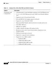
...Chapter 1 Product Overview Table 1-2 Catalyst 3512, 3524, 3524-PWR, and 3548 XL Features Feature Performance and Configuration Description • Autonegotiation of speed and duplex operation on 10/100 Ethernet ports • 12, 24, or 48 10/100 Ethernet ports...switches and servers • 8192 MAC addresses • IEEE 802.1p capable • CGMP to limit the flooding of IP multicast traffic • Broadcast storm control to prevent performance degradation from broadcast storms • SPAN port monitoring on any port • Support for command switch redundancy • Support for Cisco...
...Chapter 1 Product Overview Table 1-2 Catalyst 3512, 3524, 3524-PWR, and 3548 XL Features Feature Performance and Configuration Description • Autonegotiation of speed and duplex operation on 10/100 Ethernet ports • 12, 24, or 48 10/100 Ethernet ports...switches and servers • 8192 MAC addresses • IEEE 802.1p capable • CGMP to limit the flooding of IP multicast traffic • Broadcast storm control to prevent performance degradation from broadcast storms • SPAN port monitoring on any port • Support for command switch redundancy • Support for Cisco...
Hardware Installation Guide
Page 23
... 300 that operates on AC input and supplies DC output to the Catalyst 3524-PWR XL switch Inline Power (Catalyst 3524-PWR XL switch only) • Ability to provide inline power for Cisco IP Phones from all 24 10/100 Ethernet ports • Auto-detection and control of inline phone power on a per-port basis on...
... 300 that operates on AC input and supplies DC output to the Catalyst 3524-PWR XL switch Inline Power (Catalyst 3524-PWR XL switch only) • Ability to provide inline power for Cisco IP Phones from all 24 10/100 Ethernet ports • Auto-detection and control of inline phone power on a per-port basis on...
Hardware Installation Guide
Page 25
... UTIL DUPLX SPEED 9 10 11 12 11X 12X 13 14 13X 15 16 17 18 19 20 21 22 23 24 23X 14X 24X 10/100 ports Figure 1-5 Catalyst 3524-PWR XL Switch 1 2 GBIC module slots 30291 12 1X 34 56 78 MODE SYSTEM RPS STATUS 2X DUPLX SPEED LINE PWR 9 10 11... 12 11X 12X 13 14 13X 15 16 17 18 19 20 21 22 23 24 23X 14X 24X 10/100 inline-power ports Figure 1-6 Catalyst 3548 XL Switch 1 2 GBIC module slots 28010 SYSTEM RPS 12 1X 34 56 78 9 10 11 12 13 14 15 16 15X...
... UTIL DUPLX SPEED 9 10 11 12 11X 12X 13 14 13X 15 16 17 18 19 20 21 22 23 24 23X 14X 24X 10/100 ports Figure 1-5 Catalyst 3524-PWR XL Switch 1 2 GBIC module slots 30291 12 1X 34 56 78 MODE SYSTEM RPS STATUS 2X DUPLX SPEED LINE PWR 9 10 11... 12 11X 12X 13 14 13X 15 16 17 18 19 20 21 22 23 24 23X 14X 24X 10/100 inline-power ports Figure 1-6 Catalyst 3548 XL Switch 1 2 GBIC module slots 28010 SYSTEM RPS 12 1X 34 56 78 9 10 11 12 13 14 15 16 15X...
Hardware Installation Guide
Page 40
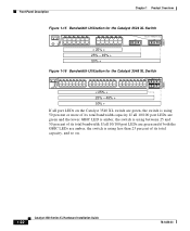
... 13 14 15 16 13X 17 18 19 20 21 22 23 24 15X 14X 16X < 25% + 25% - 49% + 50% + Catalyst 3500 XL 1 2 Figure 1-16 Bandwidth Utilization for the Catalyst 3548 XL Switch 28366 SYSTEM RPS STATUS UTIL DUPLX SPEED MODE 12 1X 3 24 56 78 9 10 11 12 13 14 15 16 15X 17... 18 17X 19 20 21 22 23 24 25 26 27 28 29 31...
... 13 14 15 16 13X 17 18 19 20 21 22 23 24 15X 14X 16X < 25% + 25% - 49% + 50% + Catalyst 3500 XL 1 2 Figure 1-16 Bandwidth Utilization for the Catalyst 3548 XL Switch 28366 SYSTEM RPS STATUS UTIL DUPLX SPEED MODE 12 1X 3 24 56 78 9 10 11 12 13 14 15 16 15X 17... 18 17X 19 20 21 22 23 24 25 26 27 28 29 31...
Hardware Installation Guide
Page 42
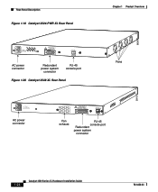
... FOR REMOTE POWER SUPPLY SPECIFIED IN MANUAL. -48V @3A, +12V @6A CONSOLE AC power connector Redundant power system connector RJ-45 console port Figure 1-20 Catalyst 3548 XL Rear Panel Chapter 1 Product Overview Fans 30293 28012 RATING 100-127/200-240V~ 1.6A/0.9A 50-60HZ AC power connector DC INPUTS FOR... REMOTE POWER SUPPLY SPECIFIED IN MANUAL +3.3V @17A, +12 @1.1A CONSOLE Fan exhaust RJ-45 console port Redundant power system connector 1-24 Catalyst 3500 Series XL Hardware Installation Guide 78-6456-03
... FOR REMOTE POWER SUPPLY SPECIFIED IN MANUAL. -48V @3A, +12V @6A CONSOLE AC power connector Redundant power system connector RJ-45 console port Figure 1-20 Catalyst 3548 XL Rear Panel Chapter 1 Product Overview Fans 30293 28012 RATING 100-127/200-240V~ 1.6A/0.9A 50-60HZ AC power connector DC INPUTS FOR... REMOTE POWER SUPPLY SPECIFIED IN MANUAL +3.3V @17A, +12 @1.1A CONSOLE Fan exhaust RJ-45 console port Redundant power system connector 1-24 Catalyst 3500 Series XL Hardware Installation Guide 78-6456-03
Hardware Installation Guide
Page 54
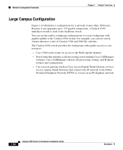
... Guide 78-6456-03 For example, you can aggregate up to 130 gigabit connections, a Catalyst 6500 multilayer switch is used as Cisco Access Digital Trunk Gateway or Cisco Access Analog Trunk Gateway) that have a mix of more than 1000 users. Because it ...use the earlier workgroup configurations to create workgroups with gigabit access to core resources: • Cisco 7000 series router for a network of Catalyst 3500 and 2900 XL switches. Network Configuration Examples Chapter 1 Product Overview Large Campus Configuration Figure 1-24 illustrates a configuration for access to the...
... Guide 78-6456-03 For example, you can aggregate up to 130 gigabit connections, a Catalyst 6500 multilayer switch is used as Cisco Access Digital Trunk Gateway or Cisco Access Analog Trunk Gateway) that have a mix of more than 1000 users. Because it ...use the earlier workgroup configurations to create workgroups with gigabit access to core resources: • Cisco 7000 series router for a network of Catalyst 3500 and 2900 XL switches. Network Configuration Examples Chapter 1 Product Overview Large Campus Configuration Figure 1-24 illustrates a configuration for access to the...
Hardware Installation Guide
Page 55
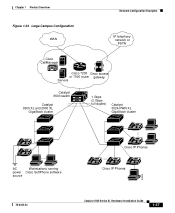
Chapter 1 Product Overview Network Configuration Examples Figure 1-24 Large Campus Configuration WAN IP telephony network or PSTN Cisco CallManager Cisco 7200 Cisco access or 7500 router gateway Servers Catalyst 6500 switch Catalyst 3500 XL and 2900 XL GigaStack cluster 1 Gbps (2 Gbps full duplex) Catalyst 3524-PWR XL GigaStack cluster IP IP AC Workstations running power Cisco SoftPhone software source IP IP Cisco IP Phones IP IP IP Cisco IP Phones 33093 78-6456-03 Catalyst 3500 Series XL Hardware Installation Guide 1-37
Chapter 1 Product Overview Network Configuration Examples Figure 1-24 Large Campus Configuration WAN IP telephony network or PSTN Cisco CallManager Cisco 7200 Cisco access or 7500 router gateway Servers Catalyst 6500 switch Catalyst 3500 XL and 2900 XL GigaStack cluster 1 Gbps (2 Gbps full duplex) Catalyst 3524-PWR XL GigaStack cluster IP IP AC Workstations running power Cisco SoftPhone software source IP IP Cisco IP Phones IP IP IP Cisco IP Phones 33093 78-6456-03 Catalyst 3500 Series XL Hardware Installation Guide 1-37
Hardware Installation Guide
Page 63
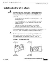
Figure 2-1 shows which mounting holes attach to ensure that the system remains stable. or 24-inch rack. Other switches in the series (Catalyst 3512, 3524, 3524-PWR, and 3548 XL) can be mounted at the bottom of the rack. • If the rack is provided with the heaviest ... with the switch can also be installed as an example. Note The illustrations in this unit in a partially filled rack, load the rack from the bottom to a 19- Figure 2-1 Bracket Mounting Points 19" rack mount point 24" rack mount point 38398 78-6456-03 19" rack mount point 24" rack mount point Catalyst 3500...
Figure 2-1 shows which mounting holes attach to ensure that the system remains stable. or 24-inch rack. Other switches in the series (Catalyst 3512, 3524, 3524-PWR, and 3548 XL) can be mounted at the bottom of the rack. • If the rack is provided with the heaviest ... with the switch can also be installed as an example. Note The illustrations in this unit in a partially filled rack, load the rack from the bottom to a 19- Figure 2-1 Bracket Mounting Points 19" rack mount point 24" rack mount point 38398 78-6456-03 19" rack mount point 24" rack mount point Catalyst 3500...
Hardware Installation Guide
Page 64
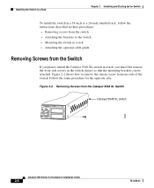
... 2 Installing and Starting Up the Switch To install the switch in a 19-inch or a 24-inch standard rack, follow the instructions described in these procedures: • Removing screws from the switch • Attaching the brackets to the switch • Mounting the switch in a rack • Attaching ... the Catalyst 3548 XL Switch 46 47 48 47X 1 2 48X Catalyst 3548 XL switch 30062 Catalyst 3500 Series XL Hardware Installation Guide 2-8 78-6456-03 Figure 2-2 Removing Screws from one side of the switch. Figure 2-2 shows how to install the Catalyst 3548 XL switch in the switch chassis ...
... 2 Installing and Starting Up the Switch To install the switch in a 19-inch or a 24-inch standard rack, follow the instructions described in these procedures: • Removing screws from the switch • Attaching the brackets to the switch • Mounting the switch in a rack • Attaching ... the Catalyst 3548 XL Switch 46 47 48 47X 1 2 48X Catalyst 3548 XL switch 30062 Catalyst 3500 Series XL Hardware Installation Guide 2-8 78-6456-03 Figure 2-2 Removing Screws from one side of the switch. Figure 2-2 shows how to install the Catalyst 3548 XL switch in the switch chassis ...

Hardware Installation Guide
Page 65
...inch rack, use the supplied number-8 Phillips flat-head screws to attach the long side of the bracket to the switch. • For a 24-inch rack, use depend on whether you use the supplied number-8 Phillips truss-head screws to attach the short side of...STATUS UTIL DUPLX SPEED 2 3 24" Configuration 22438 78-6456-03 Catalyst 3500 Series XL Hardware Installation Guide 2-9 Figure 2-3 Attaching Brackets for a 19-inch or a 24-inch rack. Chapter 2 Installing and Starting Up the Switch Installing the Switch in a Rack Attaching the Brackets to the Switch The bracket orientation and the ...
...inch rack, use the supplied number-8 Phillips flat-head screws to attach the long side of the bracket to the switch. • For a 24-inch rack, use depend on whether you use the supplied number-8 Phillips truss-head screws to attach the short side of...STATUS UTIL DUPLX SPEED 2 3 24" Configuration 22438 78-6456-03 Catalyst 3500 Series XL Hardware Installation Guide 2-9 Figure 2-3 Attaching Brackets for a 19-inch or a 24-inch rack. Chapter 2 Installing and Starting Up the Switch Installing the Switch in a Rack Attaching the Brackets to the Switch The bracket orientation and the ...
Hardware Installation Guide
Page 66
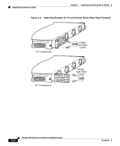
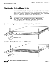
Installing the Switch in a Rack Chapter 2 Installing and Starting Up the Switch Figure 2-4 Attaching Brackets for 19- and 24-Inch Racks (Rear Panel Forward) 22439 DC INPUTS SPECIFIED IFNOMRARNEUMAOL.T+E3P.3OVW***E@R1S4UAP, PLY DC INPUT +12V***@3A 19" Configuration DC INPUTS SPECIFIED IFNOMRARNEUMAOL.T+E3P.3OVW***E@R1S4UAP, PLY DC INPUT +12V***@3A 24" Configuration Phillips flat-head screws Phillips truss-head screws 22440 2-10 Catalyst 3500 Series XL Hardware Installation Guide 78-6456-03
Installing the Switch in a Rack Chapter 2 Installing and Starting Up the Switch Figure 2-4 Attaching Brackets for 19- and 24-Inch Racks (Rear Panel Forward) 22439 DC INPUTS SPECIFIED IFNOMRARNEUMAOL.T+E3P.3OVW***E@R1S4UAP, PLY DC INPUT +12V***@3A 19" Configuration DC INPUTS SPECIFIED IFNOMRARNEUMAOL.T+E3P.3OVW***E@R1S4UAP, PLY DC INPUT +12V***@3A 24" Configuration Phillips flat-head screws Phillips truss-head screws 22440 2-10 Catalyst 3500 Series XL Hardware Installation Guide 78-6456-03
Hardware Installation Guide
Page 68
... mount it on the left or right bracket. Note The Catalyst 3548 XL switch ships with a special cable guide as shown in Figure 2-6, to attach the cable guide to the left bracket. Installing the Switch in a Rack Chapter 2 Installing and Starting Up the Switch Attaching the Optional Cable Guide We recommend attaching the cable... RPS 12 1X 34 56 78 9 10 11 12 13 14 15 16 15X 17 18 17X 19 20 21 22 23 24 25 26 27 28 29 30 31 32 31X 33 34 33X 35 36 37 38 39 40 41 42 43 44 45 46 47 ...
... mount it on the left or right bracket. Note The Catalyst 3548 XL switch ships with a special cable guide as shown in Figure 2-6, to attach the cable guide to the left bracket. Installing the Switch in a Rack Chapter 2 Installing and Starting Up the Switch Attaching the Optional Cable Guide We recommend attaching the cable... RPS 12 1X 34 56 78 9 10 11 12 13 14 15 16 15X 17 18 17X 19 20 21 22 23 24 25 26 27 28 29 30 31 32 31X 33 34 33X 35 36 37 38 39 40 41 42 43 44 45 46 47 ...
Hardware Installation Guide
Page 80
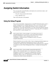
... create a default configuration for more information. 2-24 Catalyst 3500 Series XL Hardware Installation Guide 78-6456-03 Refer to assign IP information. Assigning Switch Information Chapter 2 Installing and Starting Up the Switch Assigning Switch Information You can use the Cluster Management Suite or... and the Internet. If you are configuring a command switch or standalone switch, you need to the Cisco IOS Desktop Switching Software Configuration Guide for continued operation. To run the setup program, access the switch from the PC terminal that prompts you must assign IP...
... create a default configuration for more information. 2-24 Catalyst 3500 Series XL Hardware Installation Guide 78-6456-03 Refer to assign IP information. Assigning Switch Information Chapter 2 Installing and Starting Up the Switch Assigning Switch Information You can use the Cluster Management Suite or... and the Internet. If you are configuring a command switch or standalone switch, you need to the Cisco IOS Desktop Switching Software Configuration Guide for continued operation. To run the setup program, access the switch from the PC terminal that prompts you must assign IP...
Hardware Installation Guide
Page 95
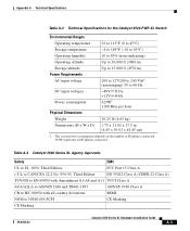
Table A-4 Catalyst 3500 Series XL Agency Approvals Safety EMC UL to UL 1950, Third Edition FCC Part 15 Class A c-UL to CAN/CSA 22.2 No. 950-95, Third Edition EN 55022 Class A (CISPR 22 Class A) TUV/GS to EN 60950 with Amendment A1-A4 and A11 VCCI...45 cm) 1. The actual power consumption depends on the number of IP phones connected. 325W represents 24 IP phones connected. Appendix A Technical Specifications Table A-3 Technical Specifications for the Catalyst 3524-PWR XL Switch Environmental Ranges Operating temperature 32 to 113°F (0 to 45°C) Storage temperature -4 to ...
Table A-4 Catalyst 3500 Series XL Agency Approvals Safety EMC UL to UL 1950, Third Edition FCC Part 15 Class A c-UL to CAN/CSA 22.2 No. 950-95, Third Edition EN 55022 Class A (CISPR 22 Class A) TUV/GS to EN 60950 with Amendment A1-A4 and A11 VCCI...45 cm) 1. The actual power consumption depends on the number of IP phones connected. 325W represents 24 IP phones connected. Appendix A Technical Specifications Table A-3 Technical Specifications for the Catalyst 3524-PWR XL Switch Environmental Ranges Operating temperature 32 to 113°F (0 to 45°C) Storage temperature -4 to ...
Hardware Installation Guide
Page 137
and 24-inch racks 2-7 A AC power connecting to 2-15 connector 1-25 specifications A-1, A-2, A-3 adapter pinouts, terminal RJ-45-to-DB-25 B-7 RJ-45-to-DB-9 B-6 78-6456-03 ... ports 1-10 cable lengths 2-5 connecting to 2-19 to 2-21 connectors and cables B-2 to B-3 GigaStack GBIC ports B-3 pinouts B-4 See also connectors and cables cautions xi CGMP 1-3 Catalyst 3500 Series XL Hardware Installation Guide 1
and 24-inch racks 2-7 A AC power connecting to 2-15 connector 1-25 specifications A-1, A-2, A-3 adapter pinouts, terminal RJ-45-to-DB-25 B-7 RJ-45-to-DB-9 B-6 78-6456-03 ... ports 1-10 cable lengths 2-5 connecting to 2-19 to 2-21 connectors and cables B-2 to B-3 GigaStack GBIC ports B-3 pinouts B-4 See also connectors and cables cautions xi CGMP 1-3 Catalyst 3500 Series XL Hardware Installation Guide 1

Hardware Installation Guide
Page 140
...also procedures warning C-7 Inter-Switch Link (ISL) 1-3 IOS command-line interface 1-27 IP address procedures 2-24 IP setup 2-25 J jewelry removal warning C-8 L LAN-to-phone jack 2-17 LEDs Catalyst 3508G XL front panel 1-12 Catalyst 3512 and 3524 XL front panel 1-13 Catalyst 3548 XL front panel 1-...activity warning C-25 line power See inline power M management features and defaults 2-29 Mode button 1-12, 1-18 Mode label (on Catalyst 3548 XL only) 1-18 models, switch 1-2 mounting, table or desk 2-15 mounting brackets 2-7 attaching 2-9, 2-13 rack-mount 2-11 wall-mount 2-14 N network configuration...
...also procedures warning C-7 Inter-Switch Link (ISL) 1-3 IOS command-line interface 1-27 IP address procedures 2-24 IP setup 2-25 J jewelry removal warning C-8 L LAN-to-phone jack 2-17 LEDs Catalyst 3508G XL front panel 1-12 Catalyst 3512 and 3524 XL front panel 1-13 Catalyst 3548 XL front panel 1-...activity warning C-25 line power See inline power M management features and defaults 2-29 Mode button 1-12, 1-18 Mode label (on Catalyst 3548 XL only) 1-18 models, switch 1-2 mounting, table or desk 2-15 mounting brackets 2-7 attaching 2-9, 2-13 rack-mount 2-11 wall-mount 2-14 N network configuration...
Hardware Installation Guide
Page 141
...10 See also 10/100, 1000BaseX, inline power POST LEDs 3-2 results 2-15, 3-1, 3-2 power connecting to 2-15 power connectors 1-23 to 1-24, 1-25 power on 2-15 power specifications A-1, A-2, A-3 power supply AC power outlet 1-25 RPS connector 1-25 warning C-22 procedures connection 2-16... to 2-23 installation 2-5 to 2-15 IP address 2-24 product disposal warning C-26 PSTN 1-36 publications, related xiv Public Switched Telephone Network See PSTN Q qualified personnel warning C-6 78-6456-03 Catalyst 3500 Series XL Hardware Installation Guide 5
...10 See also 10/100, 1000BaseX, inline power POST LEDs 3-2 results 2-15, 3-1, 3-2 power connecting to 2-15 power connectors 1-23 to 1-24, 1-25 power on 2-15 power specifications A-1, A-2, A-3 power supply AC power outlet 1-25 RPS connector 1-25 warning C-22 procedures connection 2-16... to 2-23 installation 2-5 to 2-15 IP address 2-24 product disposal warning C-26 PSTN 1-36 publications, related xiv Public Switched Telephone Network See PSTN Q qualified personnel warning C-6 78-6456-03 Catalyst 3500 Series XL Hardware Installation Guide 5
Hardware Installation Guide
Page 142
...program 2-24 to 2-27 shelf-mounting 2-15 slots See ports 1-10 SNMP network management platforms 1-3, 1-27 software by model 1-2 software switch management 1-27 specifications A-1 stacking the chassis warning C-10 standard edition software, switches running ...switch applications 1-28 startup powering on 2-15 system LED 1-15 T table-mounting 2-15 technical specifications A-1 Telnet, and accessing the CLI 1-27 temperature operating A-1 warning C-13 terminal, connecting to switch 2-22 terminal emulation software 2-22 TN power warning C-15 translated warnings C-1 troubleshooting 3-1 to 3-5 Catalyst...
...program 2-24 to 2-27 shelf-mounting 2-15 slots See ports 1-10 SNMP network management platforms 1-3, 1-27 software by model 1-2 software switch management 1-27 specifications A-1 stacking the chassis warning C-10 standard edition software, switches running ...switch applications 1-28 startup powering on 2-15 system LED 1-15 T table-mounting 2-15 technical specifications A-1 Telnet, and accessing the CLI 1-27 temperature operating A-1 warning C-13 terminal, connecting to switch 2-22 terminal emulation software 2-22 TN power warning C-15 translated warnings C-1 troubleshooting 3-1 to 3-5 Catalyst...
