Hardware Installation Guide
Page 19
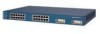
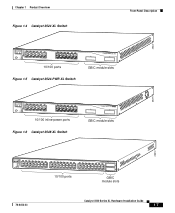
... Catalyst 3500 Series XL Hardware Installation Guide 1-1 A feature specific to the Catalyst 3524-PWR XL switch is its ability to provide inline power to Cisco IP Phones. (Phone adapters are stackable 10/100 Ethernet switches to the Catalyst 3524-PWR XL 10/100 switch ports.) Figure 1-1 shows the switch models in different network topologies Features The Catalyst 3500 series XL switches-also referred to as Catalyst 3500 XL switches...
... Catalyst 3500 Series XL Hardware Installation Guide 1-1 A feature specific to the Catalyst 3524-PWR XL switch is its ability to provide inline power to Cisco IP Phones. (Phone adapters are stackable 10/100 Ethernet switches to the Catalyst 3524-PWR XL 10/100 switch ports.) Figure 1-1 shows the switch models in different network topologies Features The Catalyst 3500 series XL switches-also referred to as Catalyst 3500 XL switches...
Hardware Installation Guide
Page 23
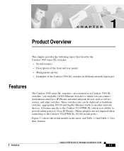
... on AC input and supplies DC output to the Catalyst 3512, 3524, and 3548 XL switches • Connection for optional Cisco RPS 300 that operates on AC input and supplies DC output to the Catalyst 3524-PWR XL switch Inline Power (Catalyst 3524-PWR XL switch only) • Ability to provide inline power for Cisco IP Phones from all 24 10/100 Ethernet ports...
... on AC input and supplies DC output to the Catalyst 3512, 3524, and 3548 XL switches • Connection for optional Cisco RPS 300 that operates on AC input and supplies DC output to the Catalyst 3524-PWR XL switch Inline Power (Catalyst 3524-PWR XL switch only) • Ability to provide inline power for Cisco IP Phones from all 24 10/100 Ethernet ports...
Hardware Installation Guide
Page 24
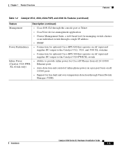
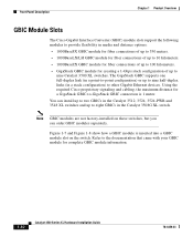
... a Mode label that you press.) These front-panel components are described in this section. All Catalyst 3500 XL switches have a set of the Catalyst 3512, 3524, 3524-PWR and 3548 XL switches (Figure 1-3, Figure 1-4, Figure 1-5, and Figure 1-6) have 10/100 RJ-45 ports and two 1000BaseX GBIC module slots. Front-Panel Description Chapter 1 Product Overview Front-Panel ...
... a Mode label that you press.) These front-panel components are described in this section. All Catalyst 3500 XL switches have a set of the Catalyst 3512, 3524, 3524-PWR and 3548 XL switches (Figure 1-3, Figure 1-4, Figure 1-5, and Figure 1-6) have 10/100 RJ-45 ports and two 1000BaseX GBIC module slots. Front-Panel Description Chapter 1 Product Overview Front-Panel ...
Hardware Installation Guide
Page 25
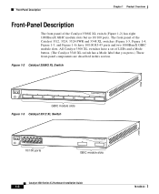
Chapter 1 Product Overview Figure 1-4 Catalyst 3524 XL Switch Front-Panel Description 26237 12 1X 34 56 78 MODE SYSTEM RPS STATUS 2X UTIL DUPLX SPEED 9 10 11 12 11X 12X 13 14 13X 15 16 17 18 19 20 21 22 23 24 23X 14X 24X 10/100 ports Figure 1-5 Catalyst 3524-PWR XL Switch 1 2 GBIC module slots 30291...
Chapter 1 Product Overview Figure 1-4 Catalyst 3524 XL Switch Front-Panel Description 26237 12 1X 34 56 78 MODE SYSTEM RPS STATUS 2X UTIL DUPLX SPEED 9 10 11 12 11X 12X 13 14 13X 15 16 17 18 19 20 21 22 23 24 23X 14X 24X 10/100 ports Figure 1-5 Catalyst 3524-PWR XL Switch 1 2 GBIC module slots 30291...

Hardware Installation Guide
Page 26
... the cables are the left-most pair. When connecting the switch to workstations, servers, routers, and Cisco IP Phones, be sure that the cable is above port 4, and so on the Catalyst 3512, 3524, 3524-PWR, and 3548 XL switches are grouped in pairs. The 10/100 switch ports can be set to any combination of the attached...
... the cables are the left-most pair. When connecting the switch to workstations, servers, routers, and Cisco IP Phones, be sure that the cable is above port 4, and so on the Catalyst 3512, 3524, 3524-PWR, and 3548 XL switches are grouped in pairs. The 10/100 switch ports can be set to any combination of the attached...
Hardware Installation Guide
Page 27
... Catalyst 3524-PWR XL 10/100 ports can control whether or not a Catalyst 3524-PWR XL 10/100 port automatically provides power when a Cisco IP Phone is the default. Refer to the Cisco IOS Desktop Switching Software Configuration Guide for Cisco IP Phones. Chapter 1 Product Overview Front-Panel Description The 10/100 ports on the Catalyst 3512, 3524, 3524-PWR, and 3548 XL switches provide...
... Catalyst 3524-PWR XL 10/100 ports can control whether or not a Catalyst 3524-PWR XL 10/100 port automatically provides power when a Cisco IP Phone is the default. Refer to the Cisco IOS Desktop Switching Software Configuration Guide for Cisco IP Phones. Chapter 1 Product Overview Front-Panel Description The 10/100 ports on the Catalyst 3512, 3524, 3524-PWR, and 3548 XL switches provide...
Hardware Installation Guide
Page 28
... that came with your GBIC module for complete GBIC module information. 1-10 Catalyst 3500 Series XL Hardware Installation Guide 78-6456-03 Note GBIC modules are not factory-installed on the switch. You can order GBIC modules separately. Front-Panel Description Chapter 1 Product Overview... is inserted into a GBIC module slot on these switches, but you can install up to two GBICs in the Catalyst 3512, 3524, 3524-PWR and 3548 XL switches and up to eight GBICs in the Catalyst 3508G XL switch. Using the required Cisco proprietary signaling and cabling, the maximum distance for ...
... that came with your GBIC module for complete GBIC module information. 1-10 Catalyst 3500 Series XL Hardware Installation Guide 78-6456-03 Note GBIC modules are not factory-installed on the switch. You can order GBIC modules separately. Front-Panel Description Chapter 1 Product Overview... is inserted into a GBIC module slot on these switches, but you can install up to two GBICs in the Catalyst 3512, 3524, 3524-PWR and 3548 XL switches and up to eight GBICs in the Catalyst 3508G XL switch. Using the required Cisco proprietary signaling and cabling, the maximum distance for ...
Hardware Installation Guide
Page 34
... have failed. Amber RPS is connected but not functioning properly. Note The Cisco RPS 600 (model PWR600-AC-RPS) supports the Catalyst 3512, 3524, 3548, and 3508 XL switches. For more information see the "RPS Connector on the Catalyst 3508, 3512, 3524, and 3548 XL Switches" section on the bottom of the power supplies in the RPS could be...
... have failed. Amber RPS is connected but not functioning properly. Note The Cisco RPS 600 (model PWR600-AC-RPS) supports the Catalyst 3512, 3524, 3548, and 3508 XL switches. For more information see the "RPS Connector on the Catalyst 3508, 3512, 3524, and 3548 XL Switches" section on the bottom of the power supplies in the RPS could be...
Hardware Installation Guide
Page 35
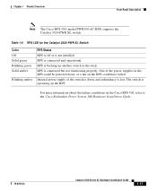
...stack. For more information about the failure conditions on the RPS could have failed. Table 1-5 RPS LED for the Catalyst 3524-PWR XL Switch Color Off Solid green Blinking green Solid amber Blinking amber RPS Status RPS is off or is lost. RPS is backing ...switch is down , or a fan on the Cisco RPS 300, refer to the Cisco Redundant Power System 300 Hardware Installation Guide. 78-6456-03 Catalyst 3500 Series XL Hardware Installation Guide 1-17 Chapter 1 Product Overview Front-Panel Description Note The Cisco RPS 300 (model PWR300-AC-RPS) supports the Catalyst 3524-PWR XL switch....
...stack. For more information about the failure conditions on the RPS could have failed. Table 1-5 RPS LED for the Catalyst 3524-PWR XL Switch Color Off Solid green Blinking green Solid amber Blinking amber RPS Status RPS is off or is lost. RPS is backing ...switch is down , or a fan on the Cisco RPS 300, refer to the Cisco Redundant Power System 300 Hardware Installation Guide. 78-6456-03 Catalyst 3500 Series XL Hardware Installation Guide 1-17 Chapter 1 Product Overview Front-Panel Description Note The Cisco RPS 300 (model PWR300-AC-RPS) supports the Catalyst 3524-PWR XL switch....
Hardware Installation Guide
Page 37
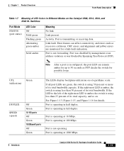
...management or an address violation or was blocked by Spanning Tree Protocol (STP). Port is operating at 1000 Mbps. 78-6456-03 Catalyst 3500 Series XL Hardware Installation Guide 1-19 Port is transmitting or receiving data. Port is operating in half duplex. Port is not operating. Port ...percent of its total bandwidth capacity. If the right-most LED is amber, the switch is using 50 percent or more of LED Colors in Different Modes on the Catalyst 3508, 3512, 3524, and 3548 XL Switches Port Mode STATUS (port status) LED Color Off Solid green Flashing green Alternating ...
...management or an address violation or was blocked by Spanning Tree Protocol (STP). Port is operating at 1000 Mbps. 78-6456-03 Catalyst 3500 Series XL Hardware Installation Guide 1-19 Port is transmitting or receiving data. Port is operating in half duplex. Port is not operating. Port ...percent of its total bandwidth capacity. If the right-most LED is amber, the switch is using 50 percent or more of LED Colors in Different Modes on the Catalyst 3508, 3512, 3524, and 3548 XL Switches Port Mode STATUS (port status) LED Color Off Solid green Flashing green Alternating ...
Hardware Installation Guide
Page 38
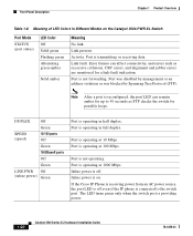
... half duplex. Port is transmitting or receiving data. Port is operating at 10 Mbps. If the Cisco IP Phone is receiving power from an AC power source, the port LED is on the Catalyst 3524-PWR XL Switch Port Mode STATUS (port status) LED Color Off Solid green Flashing green Alternating green-amber Solid amber...
... half duplex. Port is transmitting or receiving data. Port is operating at 10 Mbps. If the Cisco IP Phone is receiving power from an AC power source, the port LED is on the Catalyst 3524-PWR XL Switch Port Mode STATUS (port status) LED Color Off Solid green Flashing green Alternating green-amber Solid amber...
Hardware Installation Guide
Page 39
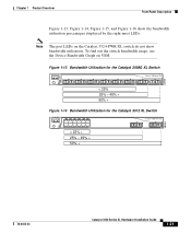
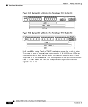
... 56 78 9 10 11 12 11X 2X 12X < 25% + 25% - 49% + 50% + Catalyst 3500 XL 1 2 38399 78-6456-03 Catalyst 3500 Series XL Hardware Installation Guide 1-21 To find out the switch bandwidth usage, use the Device Bandwidth Graph on the Catalyst 3524-PWR XL switch do not show bandwidth utilization. Chapter 1 Product Overview Front-Panel Description Figure 1-13...
... 56 78 9 10 11 12 11X 2X 12X < 25% + 25% - 49% + 50% + Catalyst 3500 XL 1 2 38399 78-6456-03 Catalyst 3500 Series XL Hardware Installation Guide 1-21 To find out the switch bandwidth usage, use the Device Bandwidth Graph on the Catalyst 3524-PWR XL switch do not show bandwidth utilization. Chapter 1 Product Overview Front-Panel Description Figure 1-13...
Hardware Installation Guide
Page 40
Front-Panel Description Chapter 1 Product Overview 22007 Figure 1-15 Bandwidth Utilization for the Catalyst 3524 XL Switch MODE SYSTEM RPS STATUS UTIL DUPLX SPEED 12 1X 34 56 78 9 10 11 12 11X 2X 12X 13 14 15 16 13X 17 18 ...19 20 21 22 23 24 15X 14X 16X < 25% + 25% - 49% + 50% + Catalyst 3500 XL 1 2 Figure 1-16 Bandwidth Utilization for the Catalyst 3548 XL Switch 28366 SYSTEM RPS STATUS UTIL DUPLX SPEED MODE 12 1X 3 24 56 78 9 10 11 12 13 14 15 16 15X...
Front-Panel Description Chapter 1 Product Overview 22007 Figure 1-15 Bandwidth Utilization for the Catalyst 3524 XL Switch MODE SYSTEM RPS STATUS UTIL DUPLX SPEED 12 1X 34 56 78 9 10 11 12 11X 2X 12X 13 14 15 16 13X 17 18 ...19 20 21 22 23 24 15X 14X 16X < 25% + 25% - 49% + 50% + Catalyst 3500 XL 1 2 Figure 1-16 Bandwidth Utilization for the Catalyst 3548 XL Switch 28366 SYSTEM RPS STATUS UTIL DUPLX SPEED MODE 12 1X 3 24 56 78 9 10 11 12 13 14 15 16 15X...
Hardware Installation Guide
Page 41
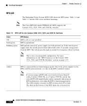
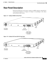
....T+E3P.3OVW***E@R1S4UAP, PLY DC INPUT +12V***@3A AC power connector RJ-45 console port Redundant power system connector Figure 1-18 Catalyst 3512 and 3524 XL Rear Panel Fans 18964 RATING 100-127/200-240V~ 1.0A/0.5A 50-60HZ AC power connector 78-6456-03 CONSOLE DC INPUTS... MANUAL. +5V @24A, +12V @.5A RJ-45 console port Redundant power system connector Fans Catalyst 3500 Series XL Hardware Installation Guide 1-23 Chapter 1 Product Overview Rear-Panel Description Rear-Panel Description Switch rear panels have an AC power connector, an RPS connector, and an RJ-45 console port ...
....T+E3P.3OVW***E@R1S4UAP, PLY DC INPUT +12V***@3A AC power connector RJ-45 console port Redundant power system connector Figure 1-18 Catalyst 3512 and 3524 XL Rear Panel Fans 18964 RATING 100-127/200-240V~ 1.0A/0.5A 50-60HZ AC power connector 78-6456-03 CONSOLE DC INPUTS... MANUAL. +5V @24A, +12V @.5A RJ-45 console port Redundant power system connector Fans Catalyst 3500 Series XL Hardware Installation Guide 1-23 Chapter 1 Product Overview Rear-Panel Description Rear-Panel Description Switch rear panels have an AC power connector, an RPS connector, and an RJ-45 console port ...

Hardware Installation Guide
Page 43
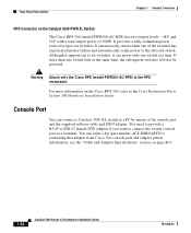
Cisco RPS Connector Specific Cisco RPS models support specific Catalyst 3500 XL switches: • Cisco RPS 600 (model PWR600-AC-RPS)-Supports the Catalyst 3512, 3524, 3548, and 3508 XL switches • Cisco RPS 300 (model PWR300-AC-RPS)-Supports the Catalyst 3524-PWR XL switch RPS Connector on RPS. The AC input to the Cisco RPS is not. Warning Attach only the Cisco... DC output to the RPS receptacle. For more information on the Cisco RPS 600, refer to a powered-on the Catalyst 3508, 3512, 3524, and 3548 XL Switches The Cisco RPS 600 (model PWR600-AC-RPS) provides a quasi-redundant power...
Cisco RPS Connector Specific Cisco RPS models support specific Catalyst 3500 XL switches: • Cisco RPS 600 (model PWR600-AC-RPS)-Supports the Catalyst 3512, 3524, 3548, and 3508 XL switches • Cisco RPS 300 (model PWR300-AC-RPS)-Supports the Catalyst 3524-PWR XL switch RPS Connector on RPS. The AC input to the Cisco RPS is not. Warning Attach only the Cisco... DC output to the RPS receptacle. For more information on the Cisco RPS 600, refer to a powered-on the Catalyst 3508, 3512, 3524, and 3548 XL Switches The Cisco RPS 600 (model PWR600-AC-RPS) provides a quasi-redundant power...
Hardware Installation Guide
Page 44
... RPS receptacle. Console Port You can order a kit (part number ACS-DSBUASYN=) containing that adapter from Cisco. For console port and adapter pinout information, see the "Cable and Adapter Specifications" section on the Catalyst 3524-PWR XL Switch The Cisco RPS 300 (model PWR300-AC-RPS) has two output levels: -48V and 12V with a total output...
... RPS receptacle. Console Port You can order a kit (part number ACS-DSBUASYN=) containing that adapter from Cisco. For console port and adapter pinout information, see the "Cable and Adapter Specifications" section on the Catalyst 3524-PWR XL Switch The Cisco RPS 300 (model PWR300-AC-RPS) has two output levels: -48V and 12V with a total output...
Hardware Installation Guide
Page 52
... of the geographic location of approximately 500 employees. Using Cisco IP Phones, Cisco CallManager software, and Cisco SoftPhone software integrates telephony and IP networks, where the IP network supports both voice and data. Each 10/100 inline-power port on the Catalyst 3524-PWR XL switches provides -48V DC power to voice traffic over data traffic. IP...
... of the geographic location of approximately 500 employees. Using Cisco IP Phones, Cisco CallManager software, and Cisco SoftPhone software integrates telephony and IP networks, where the IP network supports both voice and data. Each 10/100 inline-power port on the Catalyst 3524-PWR XL switches provides -48V DC power to voice traffic over data traffic. IP...

Hardware Installation Guide
Page 53
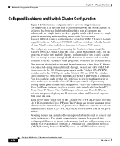
... Collapsed Backbone and Switch Cluster Configuration Gigabit servers Cisco CallManager Catalyst 4908G-L3 switch Cisco 2600 router 1 Gbps (2 Gbps full duplex) Catalyst 3500 XL and 2900 XL GigaStack cluster Catalyst 2900 XL, 1900, and 2820 cluster 200 Mbps Fast EtherChannel (400 Mbps full duplex Fast EtherChannel) Catalyst 3524-PWR XL GigaStack cluster IP IP AC power source Workstations running Cisco SoftPhone software IP IP...
... Collapsed Backbone and Switch Cluster Configuration Gigabit servers Cisco CallManager Catalyst 4908G-L3 switch Cisco 2600 router 1 Gbps (2 Gbps full duplex) Catalyst 3500 XL and 2900 XL GigaStack cluster Catalyst 2900 XL, 1900, and 2820 cluster 200 Mbps Fast EtherChannel (400 Mbps full duplex Fast EtherChannel) Catalyst 3524-PWR XL GigaStack cluster IP IP AC power source Workstations running Cisco SoftPhone software IP IP...
Hardware Installation Guide
Page 60
...of this product should be handled according to the RPS receptacle. The following warning applies to the Catalyst 3508, 3512, 3524, and 3548 XL switches: Warning Attach only the Cisco RPS (model PWR600-AC-RPS) to the RPS receptacle. regulatory information for Installation Chapter 2 Installing...or connect or disconnect cables during periods of this manual. 15456 Catalyst 3500 Series XL Hardware Installation Guide 2-4 78-6456-03 The following warning applies to the Catalyst 3524-PWR XL switch: Warning Attach only the Cisco RPS (model PWR300-AC-RPS) to all national laws and ...
...of this product should be handled according to the RPS receptacle. The following warning applies to the Catalyst 3508, 3512, 3524, and 3548 XL switches: Warning Attach only the Cisco RPS (model PWR600-AC-RPS) to the RPS receptacle. regulatory information for Installation Chapter 2 Installing...or connect or disconnect cables during periods of this manual. 15456 Catalyst 3500 Series XL Hardware Installation Guide 2-4 78-6456-03 The following warning applies to the Catalyst 3524-PWR XL switch: Warning Attach only the Cisco RPS (model PWR300-AC-RPS) to all national laws and ...
Hardware Installation Guide
Page 91
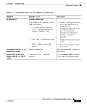
...link at both ends: • A crossover cable was required, or vice-versa. • The cable is amber on the Catalyst 3508, 3512, or 3524 XL switch. Incorrect baud rate. straight-through was used when a straight-through cables, see the "Crossover and Straight-Through Cable Pinouts" ... baud. System LED is wired incorrectly. • STP checking for LED to see which POST test failed. 78-6456-03 Catalyst 3500 Series XL Hardware Installation Guide 3-5 Resolution • For the correct pinouts and the proper application of crossover vs. Chapter 3 Troubleshooting Diagnosing ...
...link at both ends: • A crossover cable was required, or vice-versa. • The cable is amber on the Catalyst 3508, 3512, or 3524 XL switch. Incorrect baud rate. straight-through was used when a straight-through cables, see the "Crossover and Straight-Through Cable Pinouts" ... baud. System LED is wired incorrectly. • STP checking for LED to see which POST test failed. 78-6456-03 Catalyst 3500 Series XL Hardware Installation Guide 3-5 Resolution • For the correct pinouts and the proper application of crossover vs. Chapter 3 Troubleshooting Diagnosing ...


