Hardware Installation Guide
Page 6
...36 2 C H A P T E R Installing and Starting Up the Switch 2-1 Preparing for Using the Switch 1-28 Small- Contents Rear-Panel Description 1-23 Power Connectors 1-25 Internal Power Supply Connector 1-25 Cisco RPS Connector 1-25 Console Port 1-26 Management Options 1-27 Network Configuration Examples ...Switch in a Rack 2-7 Removing Screws from the Switch 2-8 Attaching the Brackets to the Switch 2-9 Mounting the Switch in a Rack 2-11 Attaching the Optional Cable Guide 2-12 Installing the Switch on a Wall 2-13 Attaching the Brackets to the Switch 2-13 Attaching the Switch to a Wall 2-14 Catalyst...
...36 2 C H A P T E R Installing and Starting Up the Switch 2-1 Preparing for Using the Switch 1-28 Small- Contents Rear-Panel Description 1-23 Power Connectors 1-25 Internal Power Supply Connector 1-25 Cisco RPS Connector 1-25 Console Port 1-26 Management Options 1-27 Network Configuration Examples ...Switch in a Rack 2-7 Removing Screws from the Switch 2-8 Attaching the Brackets to the Switch 2-9 Mounting the Switch in a Rack 2-11 Attaching the Optional Cable Guide 2-12 Installing the Switch on a Wall 2-13 Attaching the Brackets to the Switch 2-13 Attaching the Switch to a Wall 2-14 Catalyst...
Hardware Installation Guide
Page 8
...Cable B-5 Connecting to a PC B-6 Connecting to a Terminal B-7 Translated Safety Warnings C-1 Attaching the Cisco RPS (model PWR600-AC-RPS) C-2 Attaching the Cisco RPS (model PWR300-AC-RPS) C-3 Service Personnel Warning C-4 Qualified Personnel Warning C-6 Installation Warning C-7...Power Warning C-15 Ground Connection Warning C-16 Circuit Breaker (15A) Warning C-17 Grounded Equipment Warning C-19 Supply Circuit Warning C-20 No On/Off Switch Warning C-21 Power Supply Warning C-22 Lightning Activity Warning C-25 Product Disposal Warning C-26 Chassis Warning-Rack-Mounting and Servicing C-27 Catalyst...
...Cable B-5 Connecting to a PC B-6 Connecting to a Terminal B-7 Translated Safety Warnings C-1 Attaching the Cisco RPS (model PWR600-AC-RPS) C-2 Attaching the Cisco RPS (model PWR300-AC-RPS) C-3 Service Personnel Warning C-4 Qualified Personnel Warning C-6 Installation Warning C-7...Power Warning C-15 Ground Connection Warning C-16 Circuit Breaker (15A) Warning C-17 Grounded Equipment Warning C-19 Supply Circuit Warning C-20 No On/Off Switch Warning C-21 Power Supply Warning C-22 Lightning Activity Warning C-25 Product Disposal Warning C-26 Chassis Warning-Rack-Mounting and Servicing C-27 Catalyst...
Hardware Installation Guide
Page 21
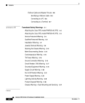
...8226; 8 GBIC-based 1000BaseX Gigabit Ethernet slots Configuration • Support for up to four 1000BaseZX GBICs with the Catalyst 3508G XL switch) Management • Cisco IOS command-line interface (CLI) through the console port or Telnet • CiscoView device-management application •... any port • Support for command switch redundancy • Support for optional Cisco 600W Redundant Power System (RPS) that operates on AC input and supplies DC output to prevent performance degradation from broadcast storms • Switch Port Analyzer (SPAN) port monitoring on all...
...8226; 8 GBIC-based 1000BaseX Gigabit Ethernet slots Configuration • Support for up to four 1000BaseZX GBICs with the Catalyst 3508G XL switch) Management • Cisco IOS command-line interface (CLI) through the console port or Telnet • CiscoView device-management application •... any port • Support for command switch redundancy • Support for optional Cisco 600W Redundant Power System (RPS) that operates on AC input and supplies DC output to prevent performance degradation from broadcast storms • Switch Port Analyzer (SPAN) port monitoring on all...
Hardware Installation Guide
Page 23
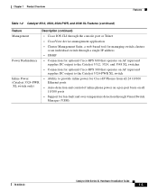
... that operates on AC input and supplies DC output to the Catalyst 3512, 3524, and 3548 XL switches • Connection for optional Cisco RPS 300 that operates on AC input and supplies DC output to the Catalyst 3524-PWR XL switch Inline Power (Catalyst 3524-PWR XL switch only) • Ability to provide inline power for Cisco IP Phones from all 24...
... that operates on AC input and supplies DC output to the Catalyst 3512, 3524, and 3548 XL switches • Connection for optional Cisco RPS 300 that operates on AC input and supplies DC output to the Catalyst 3524-PWR XL switch Inline Power (Catalyst 3524-PWR XL switch only) • Ability to provide inline power for Cisco IP Phones from all 24...
Hardware Installation Guide
Page 34
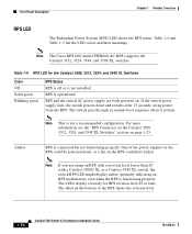
.... Note If you are both powered on the bottom of the power supplies in the RPS could have failed. RPS is connected but not functioning properly. Amber RPS is operational. Note The Cisco RPS 600 (model PWR600-AC-RPS) supports the Catalyst 3512, 3524, 3548, and 3508 XL switches. The switch goes through its normal boot sequence...
.... Note If you are both powered on the bottom of the power supplies in the RPS could have failed. RPS is connected but not functioning properly. Amber RPS is operational. Note The Cisco RPS 600 (model PWR600-AC-RPS) supports the Catalyst 3512, 3524, 3548, and 3508 XL switches. The switch goes through its normal boot sequence...
Hardware Installation Guide
Page 35
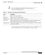
.... RPS is not installed. Internal power supply of the power supplies in the stack. The switch is lost. RPS is connected but not functioning properly. Chapter 1 Product Overview Front-Panel Description Note The Cisco RPS 300 (model PWR300-AC-RPS) supports the Catalyst 3524-PWR XL switch. RPS is backing up another switch in the RPS could have failed...
.... RPS is not installed. Internal power supply of the power supplies in the stack. The switch is lost. RPS is connected but not functioning properly. Chapter 1 Product Overview Front-Panel Description Note The Cisco RPS 300 (model PWR300-AC-RPS) supports the Catalyst 3524-PWR XL switch. RPS is backing up another switch in the RPS could have failed...
Hardware Installation Guide
Page 41
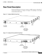
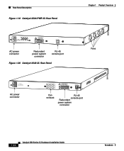
... Rear-Panel Description Rear-Panel Description Switch rear panels have an AC power connector, an RPS connector, and an RJ-45 console port (see Figure 1-17, Figure 1-19, Figure 1-18, and Figure 1-20), which are described in this section. Figure 1-17 Catalyst 3508G XL Rear Panel 18963 RATING 100...DC INPUT +12V***@3A AC power connector RJ-45 console port Redundant power system connector Figure 1-18 Catalyst 3512 and 3524 XL Rear Panel Fans 18964 RATING 100-127/200-240V~ 1.0A/0.5A 50-60HZ AC power connector 78-6456-03 CONSOLE DC INPUTS FOR REMOTE POWER SUPPLY SPECIFIED IN MANUAL. +5V @...
... Rear-Panel Description Rear-Panel Description Switch rear panels have an AC power connector, an RPS connector, and an RJ-45 console port (see Figure 1-17, Figure 1-19, Figure 1-18, and Figure 1-20), which are described in this section. Figure 1-17 Catalyst 3508G XL Rear Panel 18963 RATING 100...DC INPUT +12V***@3A AC power connector RJ-45 console port Redundant power system connector Figure 1-18 Catalyst 3512 and 3524 XL Rear Panel Fans 18964 RATING 100-127/200-240V~ 1.0A/0.5A 50-60HZ AC power connector 78-6456-03 CONSOLE DC INPUTS FOR REMOTE POWER SUPPLY SPECIFIED IN MANUAL. +5V @...
Hardware Installation Guide
Page 42
...-127/200-240V~ 3.5A/1.8A 50-60HZ DC INPUTS FOR REMOTE POWER SUPPLY SPECIFIED IN MANUAL. -48V @3A, +12V @6A CONSOLE AC power connector Redundant power system connector RJ-45 console port Figure 1-20 Catalyst 3548 XL Rear Panel Chapter 1 Product Overview Fans 30293 28012 RATING ...100-127/200-240V~ 1.6A/0.9A 50-60HZ AC power connector DC INPUTS FOR REMOTE POWER SUPPLY SPECIFIED IN MANUAL +3.3V @17A...
...-127/200-240V~ 3.5A/1.8A 50-60HZ DC INPUTS FOR REMOTE POWER SUPPLY SPECIFIED IN MANUAL. -48V @3A, +12V @6A CONSOLE AC power connector Redundant power system connector RJ-45 console port Figure 1-20 Catalyst 3548 XL Rear Panel Chapter 1 Product Overview Fans 30293 28012 RATING ...100-127/200-240V~ 1.6A/0.9A 50-60HZ AC power connector DC INPUTS FOR REMOTE POWER SUPPLY SPECIFIED IN MANUAL +3.3V @17A...

Hardware Installation Guide
Page 43
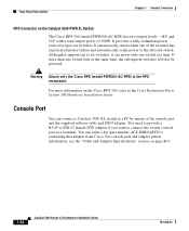
... redundant, but the DC output to the Cisco Redundant Power System Hardware Installation Guide. 78-6456-03 Catalyst 3500 Series XL Hardware Installation Guide 1-25 Warning Attach only the Cisco RPS (model PWR600-AC-RPS) to the switch either through the internal power supply or through the Cisco RPS. The switches do not support the fully-redundant configuration described...
... redundant, but the DC output to the Cisco Redundant Power System Hardware Installation Guide. 78-6456-03 Catalyst 3500 Series XL Hardware Installation Guide 1-25 Warning Attach only the Cisco RPS (model PWR600-AC-RPS) to the switch either through the internal power supply or through the Cisco RPS. The switches do not support the fully-redundant configuration described...
Hardware Installation Guide
Page 44
..., see the "Cable and Adapter Specifications" section on the Catalyst 3524-PWR XL Switch The Cisco RPS 300 (model PWR300-AC-RPS) has two output levels: -48V and 12V with a total output power of 300W. You can power only one of the console port and the supplied rollover cable and DB-9 adapter. Although it can order...
..., see the "Cable and Adapter Specifications" section on the Catalyst 3524-PWR XL Switch The Cisco RPS 300 (model PWR300-AC-RPS) has two output levels: -48V and 12V with a total output power of 300W. You can power only one of the console port and the supplied rollover cable and DB-9 adapter. Although it can order...

Hardware Installation Guide
Page 59
... ventilation openings. For systems without a power switch, line voltages are present within the power supply when the power cord is connected. 78-6456-03 Catalyst 3500 Series XL Hardware Installation Guide 2-3 Warning Unplug the power cord before you work with a power switch, line voltages are present within the power supply even when the power switch is off switch. Ensure that the host is connected...
... ventilation openings. For systems without a power switch, line voltages are present within the power supply when the power cord is connected. 78-6456-03 Catalyst 3500 Series XL Hardware Installation Guide 2-3 Warning Unplug the power cord before you work with a power switch, line voltages are present within the power supply even when the power switch is off switch. Ensure that the host is connected...

Hardware Installation Guide
Page 67
... Starting Up the Switch Installing the Switch in a Rack Mounting the Switch in a Rack After the brackets are using the Cisco RPS, see the Cisco RPS documentation for 2 seconds, and then it flashes green while the switch completes the series of POST tests described in Figure 2-5. After the power is mounted in ...the rack, attach the power cord to the rack, as shown in the "Powering On the Switch and Running POST" section on page 2-15. 78-6456-03 Catalyst 3500 Series XL Hardware Installation Guide 2-11 If you are attached to the switch, use the four supplied number-12 Phillips machine...
... Starting Up the Switch Installing the Switch in a Rack Mounting the Switch in a Rack After the brackets are using the Cisco RPS, see the Cisco RPS documentation for 2 seconds, and then it flashes green while the switch completes the series of POST tests described in Figure 2-5. After the power is mounted in ...the rack, attach the power cord to the rack, as shown in the "Powering On the Switch and Running POST" section on page 2-15. 78-6456-03 Catalyst 3500 Series XL Hardware Installation Guide 2-11 If you are attached to the switch, use the four supplied number-12 Phillips machine...
Hardware Installation Guide
Page 70
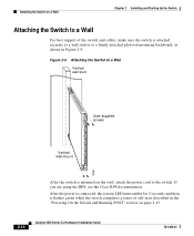
... the power is mounted on page 2-15. 2-14 Catalyst 3500 Series XL Hardware Installation Guide 78-6456-03 Figure 2-9 Attaching the Switch to the switch. If you are using the RPS, see the Cisco RPS documentation. Installing the Switch on a Wall Chapter 2 Installing and Starting Up the Switch Attaching the Switch to a Wall For best support of the switch...
... the power is mounted on page 2-15. 2-14 Catalyst 3500 Series XL Hardware Installation Guide 78-6456-03 Figure 2-9 Attaching the Switch to the switch. If you are using the RPS, see the Cisco RPS documentation. Installing the Switch on a Wall Chapter 2 Installing and Starting Up the Switch Attaching the Switch to a Wall For best support of the switch...
Hardware Installation Guide
Page 79
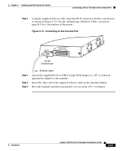
... terminal-emulation program if you are using a PC or terminal. 78-6456-03 Catalyst 3500 Series XL Hardware Installation Guide 2-23 Figure 2-13 Connecting to the Console Port 32709 CONSOLE DC INPUTS FOR REMOTE POWER SUPPLY SPECIFIED IN MANUAL. +5V @24A, +12V @1.0A RJ-45 Console port Step...attach an appropriate adapter to the Console Port Step 3 Using the supplied rollover cable, insert the RJ-45 connector into the console port, as shown in the attached adapter. Chapter 2 Installing and Starting Up the Switch Connecting a PC or Terminal to the terminal. See the "Identifying ...
... terminal-emulation program if you are using a PC or terminal. 78-6456-03 Catalyst 3500 Series XL Hardware Installation Guide 2-23 Figure 2-13 Connecting to the Console Port 32709 CONSOLE DC INPUTS FOR REMOTE POWER SUPPLY SPECIFIED IN MANUAL. +5V @24A, +12V @1.0A RJ-45 Console port Step...attach an appropriate adapter to the Console Port Step 3 Using the supplied rollover cable, insert the RJ-45 connector into the console port, as shown in the attached adapter. Chapter 2 Installing and Starting Up the Switch Connecting a PC or Terminal to the terminal. See the "Identifying ...
Hardware Installation Guide
Page 141
...See also 10/100, 1000BaseX, inline power POST LEDs 3-2 results 2-15, 3-1, 3-2 power connecting to 2-15 power connectors 1-23 to 1-24, 1-25 power on 2-15 power specifications A-1, A-2, A-3 power supply AC power outlet 1-25 RPS connector 1-25 ...warning C-22 procedures connection 2-16 to 2-23 installation 2-5 to 2-15 IP address 2-24 product disposal warning C-26 PSTN 1-36 publications, related xiv Public Switched Telephone Network See PSTN Q qualified personnel warning C-6 78-6456-03 Catalyst...
...See also 10/100, 1000BaseX, inline power POST LEDs 3-2 results 2-15, 3-1, 3-2 power connecting to 2-15 power connectors 1-23 to 1-24, 1-25 power on 2-15 power specifications A-1, A-2, A-3 power supply AC power outlet 1-25 RPS connector 1-25 ...warning C-22 procedures connection 2-16 to 2-23 installation 2-5 to 2-15 IP address 2-24 product disposal warning C-26 PSTN 1-36 publications, related xiv Public Switched Telephone Network See PSTN Q qualified personnel warning C-6 78-6456-03 Catalyst...
Hardware Installation Guide
Page 142
... See ports 1-10 SNMP network management platforms 1-3, 1-27 software by model 1-2 software switch management 1-27 specifications A-1 stacking the chassis warning C-10 standard edition software, switches running 1-2 startup powering on 2-15 straight-through cable pinouts B-4 SunNet Manager 1-27 supply circuit warning C-20 switch applications 1-28 startup powering on 2-15 system LED 1-15 T table-mounting 2-15 technical specifications A-1 Telnet...
... See ports 1-10 SNMP network management platforms 1-3, 1-27 software by model 1-2 software switch management 1-27 specifications A-1 stacking the chassis warning C-10 standard edition software, switches running 1-2 startup powering on 2-15 straight-through cable pinouts B-4 SunNet Manager 1-27 supply circuit warning C-20 switch applications 1-28 startup powering on 2-15 system LED 1-15 T table-mounting 2-15 technical specifications A-1 Telnet...

