Hardware Installation Guide
Page 6
... Guidelines 2-5 Verifying Package Contents 2-6 Installing the Switch in a Rack 2-7 Removing Screws from the Switch 2-8 Attaching the Brackets to the Switch 2-9 Mounting the Switch in a Rack 2-11 Attaching the Optional Cable Guide 2-12 Installing the Switch on a Wall 2-13 Attaching the Brackets to the Switch 2-13 Attaching the Switch to a Wall 2-14 Catalyst 3500 Series XL Hardware Installation Guide...
... Guidelines 2-5 Verifying Package Contents 2-6 Installing the Switch in a Rack 2-7 Removing Screws from the Switch 2-8 Attaching the Brackets to the Switch 2-9 Mounting the Switch in a Rack 2-11 Attaching the Optional Cable Guide 2-12 Installing the Switch on a Wall 2-13 Attaching the Brackets to the Switch 2-13 Attaching the Switch to a Wall 2-14 Catalyst 3500 Series XL Hardware Installation Guide...
Hardware Installation Guide
Page 7
...Connecting to a 1000BaseX GBIC Module Port 2-19 Connecting to a GigaStack GBIC Module Port 2-21 Connecting a PC or Terminal to the Console Port 2-22 Assigning Switch Information 2-24 Using the Setup Program 2-24 Using BOOTP 2-28 Default Configuration Settings 2-29 Where to Go Next 2-30 Troubleshooting 3-1 Understanding POST Results 3-2 Diagnosing ... Specifications B-1 10/100 Ports B-1 1000BaseX Ports B-2 Gigastack Port B-3 Console Port B-3 Cable and Adapter Specifications B-4 Crossover and Straight-Through Cable Pinouts B-4 78-6456-03 Catalyst 3500 Series XL Hardware Installation Guide vii
...Connecting to a 1000BaseX GBIC Module Port 2-19 Connecting to a GigaStack GBIC Module Port 2-21 Connecting a PC or Terminal to the Console Port 2-22 Assigning Switch Information 2-24 Using the Setup Program 2-24 Using BOOTP 2-28 Default Configuration Settings 2-29 Where to Go Next 2-30 Troubleshooting 3-1 Understanding POST Results 3-2 Diagnosing ... Specifications B-1 10/100 Ports B-1 1000BaseX Ports B-2 Gigastack Port B-3 Console Port B-3 Cable and Adapter Specifications B-4 Crossover and Straight-Through Cable Pinouts B-4 78-6456-03 Catalyst 3500 Series XL Hardware Installation Guide vii
Hardware Installation Guide
Page 8
... and Adapter Pinouts B-5 Identifying a Rollover Cable B-5 Connecting to a PC B-6 Connecting to a Terminal B-7 Translated Safety Warnings C-1 Attaching the Cisco RPS (model PWR600-AC-RPS) C-2 Attaching the Cisco RPS (model PWR300-AC-RPS) C-3 Service Personnel Warning C-4 Qualified Personnel Warning C-6 Installation Warning C-7 Jewelry Removal Warning C-8 Stacking the Chassis ...15A) Warning C-17 Grounded Equipment Warning C-19 Supply Circuit Warning C-20 No On/Off Switch Warning C-21 Power Supply Warning C-22 Lightning Activity Warning C-25 Product Disposal Warning C-26 Chassis Warning-Rack-Mounting ...
... and Adapter Pinouts B-5 Identifying a Rollover Cable B-5 Connecting to a PC B-6 Connecting to a Terminal B-7 Translated Safety Warnings C-1 Attaching the Cisco RPS (model PWR600-AC-RPS) C-2 Attaching the Cisco RPS (model PWR300-AC-RPS) C-3 Service Personnel Warning C-4 Qualified Personnel Warning C-6 Installation Warning C-7 Jewelry Removal Warning C-8 Stacking the Chassis ...15A) Warning C-17 Grounded Equipment Warning C-19 Supply Circuit Warning C-20 No On/Off Switch Warning C-21 Power Supply Warning C-22 Lightning Activity Warning C-25 Product Disposal Warning C-26 Chassis Warning-Rack-Mounting ...
Hardware Installation Guide
Page 9
... guide is for the networking or computer technician responsible for installing and configuring a Catalyst 3500 series XL switch. Purpose The Catalyst 3500 Series XL Hardware Installation Guide documents the hardware features of the switches in the series, explains how to install a switch and set up its initial configuration, provides troubleshooting information, and describes how to...
... guide is for the networking or computer technician responsible for installing and configuring a Catalyst 3500 series XL switch. Purpose The Catalyst 3500 Series XL Hardware Installation Guide documents the hardware features of the switches in the series, explains how to install a switch and set up its initial configuration, provides troubleshooting information, and describes how to...
Hardware Installation Guide
Page 10
... strategies. It also describes how to set up the switch initial configuration. Appendix B, "Connector and Cable Specifications," describes the connectors, cables, and adapters that might arise when you are installing the switch. Catalyst 3500 Series XL Hardware Installation Guide x 78-6456-03... It describes the switch ports, the standards they support, and the switch LEDs. Examples use these conventions: • Terminal sessions and system ...
... strategies. It also describes how to set up the switch initial configuration. Appendix B, "Connector and Cable Specifications," describes the connectors, cables, and adapters that might arise when you are installing the switch. Catalyst 3500 Series XL Hardware Installation Guide x 78-6456-03... It describes the switch ports, the standards they support, and the switch LEDs. Examples use these conventions: • Terminal sessions and system ...
Hardware Installation Guide
Page 14
... related products, refer to the following publications: • Quick Start: Catalyst 3500 Series XL Cabling and Setup • Cisco IOS Desktop Switching Software Configuration Guide • Cisco IOS Desktop Switching Command Reference (online only) • Cisco Cluster Management Suite online help provides detailed procedures for the Catalyst GigaStack Gigabit Interface Converter Obtaining Documentation World Wide Web You...
... related products, refer to the following publications: • Quick Start: Catalyst 3500 Series XL Cabling and Setup • Cisco IOS Desktop Switching Software Configuration Guide • Cisco IOS Desktop Switching Command Reference (online only) • Cisco Cluster Management Suite online help provides detailed procedures for the Catalyst GigaStack Gigabit Interface Converter Obtaining Documentation World Wide Web You...
Hardware Installation Guide
Page 19
..., and Table 1-1 and Table 1-2 list their features. 78-6456-03 Catalyst 3500 Series XL Hardware Installation Guide 1-1 These switches also can connect workstations and Cisco IP Phones and other network devices such as backbone switches, aggregating 10/100 and Gigabit Ethernet traffic from other switches. CH A P T E R 1 Product Overview This chapter provides the following topics that...
..., and Table 1-1 and Table 1-2 list their features. 78-6456-03 Catalyst 3500 Series XL Hardware Installation Guide 1-1 These switches also can connect workstations and Cisco IP Phones and other network devices such as backbone switches, aggregating 10/100 and Gigabit Ethernet traffic from other switches. CH A P T E R 1 Product Overview This chapter provides the following topics that...

Hardware Installation Guide
Page 20
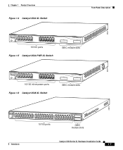
... 45 46 47 48 STATUS UTIL 47X 1 DUPLEX SPEED 2X MODE 16X 18X 32X 34X 2 48X 30210 Catalyst 3500 Series XL Hardware Installation Guide 1-2 78-6456-03 Features Chapter 1 Product Overview Figure 1-1 Catalyst 3500 Series XL Switches Switch Description WS-C3508G-XL 8 GBIC1-based gigabit module slots 1 SYSTEM 2 3 RPS 4 5 MODE STATUS UTIL DUPLX SPEED...
... 45 46 47 48 STATUS UTIL 47X 1 DUPLEX SPEED 2X MODE 16X 18X 32X 34X 2 48X 30210 Catalyst 3500 Series XL Hardware Installation Guide 1-2 78-6456-03 Features Chapter 1 Product Overview Figure 1-1 Catalyst 3500 Series XL Switches Switch Description WS-C3508G-XL 8 GBIC1-based gigabit module slots 1 SYSTEM 2 3 RPS 4 5 MODE STATUS UTIL DUPLX SPEED...
Hardware Installation Guide
Page 21
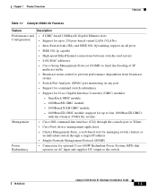
... Features Feature Description Performance and • 8 GBIC-based 1000BaseX Gigabit Ethernet slots Configuration • Support for up to four 1000BaseZX GBICs with the Catalyst 3508G XL switch) Management • Cisco IOS command-line interface (CLI) through the console port or Telnet • CiscoView device-management application • Cluster Management Suite, a web-based tool...
... Features Feature Description Performance and • 8 GBIC-based 1000BaseX Gigabit Ethernet slots Configuration • Support for up to four 1000BaseZX GBICs with the Catalyst 3508G XL switch) Management • Cisco IOS command-line interface (CLI) through the console port or Telnet • CiscoView device-management application • Cluster Management Suite, a web-based tool...
Hardware Installation Guide
Page 22
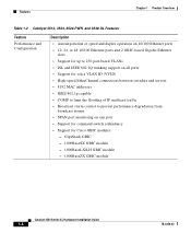
... IEEE 802.1Q trunking support on all ports • Support for voice VLAN ID (VVID) • High-speed EtherChannel connections between switches and servers • 8192 MAC addresses • IEEE 802.1p capable • CGMP to limit the flooding of IP multicast traffic ... degradation from broadcast storms • SPAN port monitoring on any port • Support for command switch redundancy • Support for Cisco GBIC modules - GigaStack GBIC - 1000BaseSX GBIC module - 1000BaseLX/LH GBIC module - 1000BaseZX GBIC module Catalyst 3500 Series XL Hardware Installation Guide 1-4 78-6456-03
... IEEE 802.1Q trunking support on all ports • Support for voice VLAN ID (VVID) • High-speed EtherChannel connections between switches and servers • 8192 MAC addresses • IEEE 802.1p capable • CGMP to limit the flooding of IP multicast traffic ... degradation from broadcast storms • SPAN port monitoring on any port • Support for command switch redundancy • Support for Cisco GBIC modules - GigaStack GBIC - 1000BaseSX GBIC module - 1000BaseLX/LH GBIC module - 1000BaseZX GBIC module Catalyst 3500 Series XL Hardware Installation Guide 1-4 78-6456-03
Hardware Installation Guide
Page 23
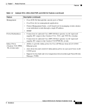
... and supplies DC output to the Catalyst 3512, 3524, and 3548 XL switches • Connection for optional Cisco RPS 300 that operates on AC input and supplies DC output to the Catalyst 3524-PWR XL switch Inline Power (Catalyst 3524-PWR XL switch only) • Ability to provide inline power for Cisco IP Phones from all 24 10...
... and supplies DC output to the Catalyst 3512, 3524, and 3548 XL switches • Connection for optional Cisco RPS 300 that operates on AC input and supplies DC output to the Catalyst 3524-PWR XL switch Inline Power (Catalyst 3524-PWR XL switch only) • Ability to provide inline power for Cisco IP Phones from all 24 10...
Hardware Installation Guide
Page 24
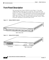
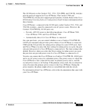
... 1-5, and Figure 1-6) have a set of the Catalyst 3508G XL switch (Figure 1-2) has eight 1000BaseX GBIC module slots but no 10/100 ports. All Catalyst 3500 XL switches have 10/100 RJ-45 ports and two 1000BaseX GBIC module slots. Figure 1-2 Catalyst 3508G XL Switch 18966 1 SYSTEM RPS MODE STATUS UTIL DUPLX SPEED ...2 3 4 5 6 7 8 GBIC module slots Figure 1-3 Catalyst 3512 XL Switch 12 1X 34 56...
... 1-5, and Figure 1-6) have a set of the Catalyst 3508G XL switch (Figure 1-2) has eight 1000BaseX GBIC module slots but no 10/100 ports. All Catalyst 3500 XL switches have 10/100 RJ-45 ports and two 1000BaseX GBIC module slots. Figure 1-2 Catalyst 3508G XL Switch 18966 1 SYSTEM RPS MODE STATUS UTIL DUPLX SPEED ...2 3 4 5 6 7 8 GBIC module slots Figure 1-3 Catalyst 3512 XL Switch 12 1X 34 56...
Hardware Installation Guide
Page 25
... 12X 13 14 13X 15 16 17 18 19 20 21 22 23 24 23X 14X 24X 10/100 ports Figure 1-5 Catalyst 3524-PWR XL Switch 1 2 GBIC module slots 30291 12 1X 34 56 78 MODE SYSTEM RPS STATUS 2X DUPLX SPEED LINE PWR 9 10 ...13 14 13X 15 16 17 18 19 20 21 22 23 24 23X 14X 24X 10/100 inline-power ports Figure 1-6 Catalyst 3548 XL Switch 1 2 GBIC module slots 28010 SYSTEM RPS 12 1X 34 56 78 9 10 11 12 13 14 15 16 15X 17... SPEED 2X 47X 1 MODE 16X 18X 32X 34X 2 48X 10/100 ports GBIC module slots 78-6456-03 Catalyst 3500 Series XL Hardware Installation Guide 1-7
... 12X 13 14 13X 15 16 17 18 19 20 21 22 23 24 23X 14X 24X 10/100 ports Figure 1-5 Catalyst 3524-PWR XL Switch 1 2 GBIC module slots 30291 12 1X 34 56 78 MODE SYSTEM RPS STATUS 2X DUPLX SPEED LINE PWR 9 10 ...13 14 13X 15 16 17 18 19 20 21 22 23 24 23X 14X 24X 10/100 inline-power ports Figure 1-6 Catalyst 3548 XL Switch 1 2 GBIC module slots 28010 SYSTEM RPS 12 1X 34 56 78 9 10 11 12 13 14 15 16 15X 17... SPEED 2X 47X 1 MODE 16X 18X 32X 34X 2 48X 10/100 ports GBIC module slots 78-6456-03 Catalyst 3500 Series XL Hardware Installation Guide 1-7

Hardware Installation Guide
Page 26
... use a crossover cable. Ports operating at 100 Mbps. Port 3 is above port 4, and so on the Catalyst 3512, 3524, 3524-PWR, and 3548 XL switches are described in pairs. These ports also can be sure that both devices support and full-duplex transmission, if ...workstations, servers, routers, and Cisco IP Phones, be set for 100BaseTX traffic. When connecting the switch to switches or hubs, use Category 3 and 4 cables, but these cables do not work for the cables are grouped in Appendix B, "Connector and Cable Specifications." Catalyst 3500 Series XL Hardware Installation ...
... use a crossover cable. Ports operating at 100 Mbps. Port 3 is above port 4, and so on the Catalyst 3512, 3524, 3524-PWR, and 3548 XL switches are described in pairs. These ports also can be sure that both devices support and full-duplex transmission, if ...workstations, servers, routers, and Cisco IP Phones, be set for 100BaseTX traffic. When connecting the switch to switches or hubs, use Category 3 and 4 cables, but these cables do not work for the cables are grouped in Appendix B, "Connector and Cable Specifications." Catalyst 3500 Series XL Hardware Installation ...
Hardware Installation Guide
Page 27
... XL Hardware Installation Guide 1-9 When you select the Auto setting for more information about Cisco IP Phones, refer to the documentation that came with the switch. However, when you can connect the Cisco IP Phone to a Catalyst 3524-PWR XL 10/100 port and to an AC power source for each 10/...and Never. If the primary source fails, the second power source becomes the primary power source to it . Cisco IP Phones-connected to the 10/100 ports on the Catalyst 3512, 3524, 3524-PWR, and 3548 XL switches provide protocol support for inline power on a port, the port only provides power if...
... XL Hardware Installation Guide 1-9 When you select the Auto setting for more information about Cisco IP Phones, refer to the documentation that came with the switch. However, when you can connect the Cisco IP Phone to a Catalyst 3524-PWR XL 10/100 port and to an AC power source for each 10/...and Never. If the primary source fails, the second power source becomes the primary power source to it . Cisco IP Phones-connected to the 10/100 ports on the Catalyst 3512, 3524, 3524-PWR, and 3548 XL switches provide protocol support for inline power on a port, the port only provides power if...
Hardware Installation Guide
Page 28
Using the required Cisco proprietary signaling and cabling, the maximum distance for a GigaStack GBIC-to-GigaStack GBIC connection is inserted into a GBIC module slot on these switches, but you can install up to two GBICs in the Catalyst 3512, 3524, 3524-PWR and 3548 XL switches and up to eight GBICs in a stack configuration) to...
Using the required Cisco proprietary signaling and cabling, the maximum distance for a GigaStack GBIC-to-GigaStack GBIC connection is inserted into a GBIC module slot on these switches, but you can install up to two GBICs in the Catalyst 3512, 3524, 3524-PWR and 3548 XL switches and up to eight GBICs in a stack configuration) to...

Hardware Installation Guide
Page 29
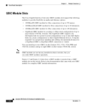
Chapter 1 Product Overview Front-Panel Description Figure 1-7 Installing a 1000BaseX GBIC Module in the Switch Metal flap door 18965 1 SYSTEM RPS MODE STATUS UTIL DUPLX SPEED 2 3 1000BaseX GBIC module GBIC module slot Figure 1-8 Installing a GigaStack GBIC Module in the Switch Metal flap door 22081 1 SYSTEM RPS MODE STATUS UTIL DUPLX SPEED 2 3 1 2 GigaStack GBIC GBIC module slot 78-6456-03 Catalyst 3500 Series XL Hardware Installation Guide 1-11
Chapter 1 Product Overview Front-Panel Description Figure 1-7 Installing a 1000BaseX GBIC Module in the Switch Metal flap door 18965 1 SYSTEM RPS MODE STATUS UTIL DUPLX SPEED 2 3 1000BaseX GBIC module GBIC module slot Figure 1-8 Installing a GigaStack GBIC Module in the Switch Metal flap door 22081 1 SYSTEM RPS MODE STATUS UTIL DUPLX SPEED 2 3 1 2 GigaStack GBIC GBIC module slot 78-6456-03 Catalyst 3500 Series XL Hardware Installation Guide 1-11
Hardware Installation Guide
Page 30
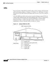
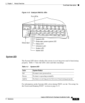
... System LED Redundant power system LED Status LED Utilization LED Duplex LED Speed LED 1-12 Catalyst 3500 Series XL Hardware Installation Guide 78-6456-03 The Cisco IOS Desktop Switching Software Configuration Guide describes how to use the Cluster Management Suite to monitor individual... switches and how to use cluster management software to monitor switch activity and its performance. All of the port...
... System LED Redundant power system LED Status LED Utilization LED Duplex LED Speed LED 1-12 Catalyst 3500 Series XL Hardware Installation Guide 78-6456-03 The Cisco IOS Desktop Switching Software Configuration Guide describes how to use the Cluster Management Suite to monitor individual... switches and how to use cluster management software to monitor switch activity and its performance. All of the port...
Hardware Installation Guide
Page 33
... LED colors during POST, see the "Powering On the Switch and Running POST" section on . Table 1-3 System LED Color Off Green Amber System Status System is operating normally. System is not powered on page 2-15. 78-6456-03 Catalyst 3500 Series XL Hardware Installation Guide 1-15 System is receiving... power but is functioning properly. Chapter 1 Product Overview Figure 1-12 Catalyst 3548 XL LEDs Port LEDs Front-Panel Description System LED 28325 SYSTEM RPS STATUS UTIL DUPLX SPEED MODE Mode label 12 1X 34 ...
... LED colors during POST, see the "Powering On the Switch and Running POST" section on . Table 1-3 System LED Color Off Green Amber System Status System is operating normally. System is not powered on page 2-15. 78-6456-03 Catalyst 3500 Series XL Hardware Installation Guide 1-15 System is receiving... power but is functioning properly. Chapter 1 Product Overview Figure 1-12 Catalyst 3548 XL LEDs Port LEDs Front-Panel Description System LED 28325 SYSTEM RPS STATUS UTIL DUPLX SPEED MODE Mode label 12 1X 34 ...
Hardware Installation Guide
Page 34
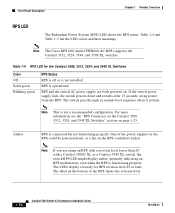
Note The Cisco RPS 600 (model PWR600-AC-RPS) supports the Catalyst 3512, 3524, 3548, and 3508 XL switches. For more information see the "RPS Connector on the Catalyst 3508, 3512, 3524, and 3548 XL Switches" section on . RPS is connected but not functioning properly. RPS and the switch AC power ...could be powered down and restarts after 15 seconds, using an RPS with a revision level lower than Z3 with a Catalyst 3508G XL or a Catalyst 3548 XL switch, the switch RPS LED might display amber (normally indicating an RPS malfunction) even when the RPS is functioning properly. One of the...
Note The Cisco RPS 600 (model PWR600-AC-RPS) supports the Catalyst 3512, 3524, 3548, and 3508 XL switches. For more information see the "RPS Connector on the Catalyst 3508, 3512, 3524, and 3548 XL Switches" section on . RPS is connected but not functioning properly. RPS and the switch AC power ...could be powered down and restarts after 15 seconds, using an RPS with a revision level lower than Z3 with a Catalyst 3508G XL or a Catalyst 3548 XL switch, the switch RPS LED might display amber (normally indicating an RPS malfunction) even when the RPS is functioning properly. One of the...


