
Software Configuration Guide
Page 80
CMS-Choose printing options, select interaction modes, display CMS preferences, install CMS on your PC or workstation. Select CMS > Installation and Distributions, and click Install. Help-Launch the online help file. Table 4-1 Toolbar Buttons Toolbar Option Icon Task Print Print a CMS ...hide the feature bar. Upgrade the software for commonly used switch and cluster configuration options and information windows such as polling intervals, the views to right on page 4-10. Catalyst 2950 and Catalyst 2955 Switch Software Configuration Guide 4-2 78-11380-10 Understanding CMS Chapter ...
CMS-Choose printing options, select interaction modes, display CMS preferences, install CMS on your PC or workstation. Select CMS > Installation and Distributions, and click Install. Help-Launch the online help file. Table 4-1 Toolbar Buttons Toolbar Option Icon Task Print Print a CMS ...hide the feature bar. Upgrade the software for commonly used switch and cluster configuration options and information windows such as polling intervals, the views to right on page 4-10. Catalyst 2950 and Catalyst 2955 Switch Software Configuration Guide 4-2 78-11380-10 Understanding CMS Chapter ...

Software Configuration Guide
Page 81
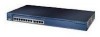
... for the active, open window. In autohide mode, the feature bar appears only when you can also click Help from this mode, the feature bar is in a sample cluster. 78-11380-10 Catalyst 2950 and Catalyst 2955 Switch Software Configuration Guide 4-3 Help for Active Window...switch. Some options from the active window or press the F1 key. 1. In this menu option are not available in your arrangement of the cluster icons in the Topology view. Figure 4-2 shows the features available in standard mode. Refresh Update the views with CMS Understanding CMS Table 4-1 Toolbar Buttons...
... for the active, open window. In autohide mode, the feature bar appears only when you can also click Help from this mode, the feature bar is in a sample cluster. 78-11380-10 Catalyst 2950 and Catalyst 2955 Switch Software Configuration Guide 4-3 Help for Active Window...switch. Some options from the active window or press the F1 key. 1. In this menu option are not available in your arrangement of the cluster icons in the Topology view. Figure 4-2 shows the features available in standard mode. Refresh Update the views with CMS Understanding CMS Table 4-1 Toolbar Buttons...
Software Configuration Guide
Page 84
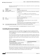
... or popup menu to guide mode, wizards provide a step-by clicking the Help button. Understanding CMS Figure 4-3 Guide Mode and Wizards Chapter 4 Getting Started with CMS 2 1 116226 Expert Mode 1 Guide mode icon 2 Wizards Guide mode is not available if your switch access level is for users...about the read -only access mode, see the "Privilege Levels" section on page 4-6. Unlike guide mode, a wizard does not prompt you select a feature that has Wizard in the name, the wizard launches for read -only. Catalyst 2950 and Catalyst 2955 Switch Software Configuration Guide 4-6 78-...
... or popup menu to guide mode, wizards provide a step-by clicking the Help button. Understanding CMS Figure 4-3 Guide Mode and Wizards Chapter 4 Getting Started with CMS 2 1 116226 Expert Mode 1 Guide mode icon 2 Wizards Guide mode is not available if your switch access level is for users...about the read -only access mode, see the "Privilege Levels" section on page 4-6. Unlike guide mode, a wizard does not prompt you select a feature that has Wizard in the name, the wizard launches for read -only. Catalyst 2950 and Catalyst 2955 Switch Software Configuration Guide 4-6 78-...
Software Configuration Guide
Page 108
... boot copy running on UNIX or DOS systems. Environment variables that have default values. 5-14 Catalyst 2950 and Catalyst 2955 Switch Software Configuration Guide 78-11380-10 A variable that is a variable with a value. Unplug the switch power cord, and press the switch Mode button while reconnecting the power cord. it has a value if it is a null string. Modifying...
... boot copy running on UNIX or DOS systems. Environment variables that have default values. 5-14 Catalyst 2950 and Catalyst 2955 Switch Software Configuration Guide 78-11380-10 A variable that is a variable with a value. Unplug the switch power cord, and press the switch Mode button while reconnecting the power cord. it has a value if it is a null string. Modifying...
Software Configuration Guide
Page 619
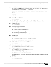
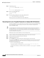
... to match that particular speed. Enter global configuration mode: switch# configure terminal 78-11380-10 Catalyst 2950 and Catalyst 2955 Switch Software Configuration Guide 32-3 You can use the following normal commands to its original name: switch# rename flash:config.text.old flash:config.text ... finish loading the operating system software: flash_init load_helper boot Step 5 Initialize the flash file system: switch# flash_init Step 6 Step 7 If you can release the Mode button a second or two after the LED above port 1X turns off. Several lines of information about...
... to match that particular speed. Enter global configuration mode: switch# configure terminal 78-11380-10 Catalyst 2950 and Catalyst 2955 Switch Software Configuration Guide 32-3 You can use the following normal commands to its original name: switch# rename flash:config.text.old flash:config.text ... finish loading the operating system software: flash_init load_helper boot Step 5 Initialize the flash file system: switch# flash_init Step 6 Step 7 If you can release the Mode button a second or two after the LED above port 1X turns off. Several lines of information about...
Software Configuration Guide
Page 620
... PC with this during the recovery process. Unplug the switch power cord. Press the Mode button, and at the same time, reconnect the power cord to the startup configuration file: switch# copy running-config startup-config The new password is the default configuration for Catalyst 2950 LRE switches. Follow these steps if you are an end user...
... PC with this during the recovery process. Unplug the switch power cord. Press the Mode button, and at the same time, reconnect the power cord to the startup configuration file: switch# copy running-config startup-config The new password is the default configuration for Catalyst 2950 LRE switches. Follow these steps if you are an end user...
Software Configuration Guide
Page 623
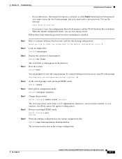
... with the configuration dialog? [yes/no ), the normal boot process continues as if the Mode button had not been pressed; To continue with password recovery, enter N at the prompt: Continue...mode: Switch (config)# exit Switch# Write the running configuration to the startup configuration file: Switch# copy running-config startup-config The new password is now in the directory. Y Load any helper files: Switch# load_helper Display the contents of flash memory: switch# dir flash: The switch file system appears in the startup configuration. 78-11380-10 Catalyst 2950 and Catalyst 2955 Switch...
... with the configuration dialog? [yes/no ), the normal boot process continues as if the Mode button had not been pressed; To continue with password recovery, enter N at the prompt: Continue...mode: Switch (config)# exit Switch# Write the running configuration to the startup configuration file: Switch# copy running-config startup-config The new password is now in the directory. Y Load any helper files: Switch# load_helper Display the contents of flash memory: switch# dir flash: The switch file system appears in the startup configuration. 78-11380-10 Catalyst 2950 and Catalyst 2955 Switch...

Hardware Installation Guide
Page 23
... is not supported by certain Catalyst 2950 LRE switches. Figure 1-1 Catalyst 2950-12 Switch 45568 SYST RPS STAT UTIL DUPLX SPEED MODE 1x 2x 3x 4x 5x 6x 7x 8x 9x 10x 11x 10Base-T / 100Base-TX 12x 10/100 ports Catalyst 2950 SERIES OL-6156-01 Catalyst 2950 Switch Hardware Installation Guide 1-3 Chapter ... Catalyst 2950ST-8 LRE Cisco 575 LRE Yes CPE Cisco 576 LRE 997 No CPE Cisco 585 LRE Yes CPE Catalyst 2950ST-24 LRE Catalyst 2950ST-24 LRE 997 Yes No No Yes Yes No Front-Panel Description The switch front panel contains the ports, the LEDs, and the Mode button....
... is not supported by certain Catalyst 2950 LRE switches. Figure 1-1 Catalyst 2950-12 Switch 45568 SYST RPS STAT UTIL DUPLX SPEED MODE 1x 2x 3x 4x 5x 6x 7x 8x 9x 10x 11x 10Base-T / 100Base-TX 12x 10/100 ports Catalyst 2950 SERIES OL-6156-01 Catalyst 2950 Switch Hardware Installation Guide 1-3 Chapter ... Catalyst 2950ST-8 LRE Cisco 575 LRE Yes CPE Cisco 576 LRE 997 No CPE Cisco 585 LRE Yes CPE Catalyst 2950ST-24 LRE Catalyst 2950ST-24 LRE 997 Yes No No Yes Yes No Front-Panel Description The switch front panel contains the ports, the LEDs, and the Mode button....

Hardware Installation Guide
Page 33
... of the Mode button that you use to monitor switch activity and performance. Figure 1-15 LEDs on Catalyst 2950-12, 2950-24, 2950C-24, 2950SX-24, and 2950T-24 Switches RPS LED Port status LEDs System LED Port mode LEDs SYST RPS STAT UTIL DUPLX SPEED MODE Mode button 1x 2x 3x 4x 5x 6x 52918 OL-6156-01 Catalyst 2950 Switch Hardware Installation...
... of the Mode button that you use to monitor switch activity and performance. Figure 1-15 LEDs on Catalyst 2950-12, 2950-24, 2950C-24, 2950SX-24, and 2950T-24 Switches RPS LED Port status LEDs System LED Port mode LEDs SYST RPS STAT UTIL DUPLX SPEED MODE Mode button 1x 2x 3x 4x 5x 6x 52918 OL-6156-01 Catalyst 2950 Switch Hardware Installation...
Hardware Installation Guide
Page 34
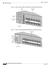
...-12-EI, 2950G-24-EI, and 2950G-24-EI-DC Switches RPS LED Port status LEDs 65395 System LED Port mode LEDs SYST RPS STAT UTIL DUPLX SPEED MODE 1 1X 23 45 67 8 9 10 11 12 11X 2X 12X Mode button Figure 1-17 LEDs on Catalyst 2950G-48-EI, 2950SX-48-SI, and 2950T-48-SI... Switches Port status LEDs System LED RPS LED Port mode LEDs SYST RPS STAT UTIL DUPLX SPEED MODE 1 1X 23 45 67 89 10 11 12 13 14 15 16 15X 2X 16X Mode button 65508 1-14 Catalyst 2950 Switch Hardware Installation...
...-12-EI, 2950G-24-EI, and 2950G-24-EI-DC Switches RPS LED Port status LEDs 65395 System LED Port mode LEDs SYST RPS STAT UTIL DUPLX SPEED MODE 1 1X 23 45 67 8 9 10 11 12 11X 2X 12X Mode button Figure 1-17 LEDs on Catalyst 2950G-48-EI, 2950SX-48-SI, and 2950T-48-SI... Switches Port status LEDs System LED RPS LED Port mode LEDs SYST RPS STAT UTIL DUPLX SPEED MODE 1 1X 23 45 67 89 10 11 12 13 14 15 16 15X 2X 16X Mode button 65508 1-14 Catalyst 2950 Switch Hardware Installation...

Hardware Installation Guide
Page 35
.../TA2I0N500G--26400HVZ~ MODE SYST RPS STAT SPEED CONSOLE 1 2 3 4 5 6 7 8 Mode button Speed LED STAT LED Figure 1-19 LEDs on Catalyst 2950ST-24 LRE 997 Switches System LED Redundant power system LED Port status LEDs -- ++ A INPCUUTR:RE3N6T- B 72 V :2-1 A SYST RPS STAT SPEED MODE CONSOLE STAT LED Speed Mode LED button 1 2 3 4 5 6 7 8 9 10 11 12 89364 OL-6156-01 Catalyst 2950 Switch Hardware Installation Guide...
.../TA2I0N500G--26400HVZ~ MODE SYST RPS STAT SPEED CONSOLE 1 2 3 4 5 6 7 8 Mode button Speed LED STAT LED Figure 1-19 LEDs on Catalyst 2950ST-24 LRE 997 Switches System LED Redundant power system LED Port status LEDs -- ++ A INPCUUTR:RE3N6T- B 72 V :2-1 A SYST RPS STAT SPEED MODE CONSOLE STAT LED Speed Mode LED button 1 2 3 4 5 6 7 8 9 10 11 12 89364 OL-6156-01 Catalyst 2950 Switch Hardware Installation Guide...

Hardware Installation Guide
Page 36
Contact Cisco Systems. Flashing amber The internal power supply in a fault condition. Port Mode and Port Status LEDs To select or change the port mode, press the Mode button (see Table 1-5) determine the type of information displayed. 1-16 Catalyst 2950 Switch Hardware Installation Guide OL-6156-01 RPS LED The RPS LED shows the RPS status. Each port has...
Contact Cisco Systems. Flashing amber The internal power supply in a fault condition. Port Mode and Port Status LEDs To select or change the port mode, press the Mode button (see Table 1-5) determine the type of information displayed. 1-16 Catalyst 2950 Switch Hardware Installation Guide OL-6156-01 RPS LED The RPS LED shows the RPS status. Each port has...

Hardware Installation Guide
Page 131
port 2-16 port mode 2-16 to 2-19 port status 2-16 RPS 2-16 speed (SPEED) 2-17 to 2-19 status (STAT) 2-17, 2-18 system 2-16 ...3-34 connection guidelines 3-30 described 2-9 illustrated 2-5 LEDs 2-17, 2-18 problems, solving 4-4 See also RJ-21 connector LRE uplink ports 2-9 M management options 2-24 Mode button 2-16 mounting desk 3-17 rack 3-7 to 3-16 shelf 3-17 table 3-17 mounting brackets, attaching 3-8 to 3-15, 3-17 MT-RJ connector B-4 OL-6156-01...RJ-21 connector B-8 to B-10 RJ-45-to-DB-25 terminal adapter B-11 RJ-45-to-DB-9 adapter cable B-10 Catalyst 2950 Switch Hardware Installation Guide IN-5
port 2-16 port mode 2-16 to 2-19 port status 2-16 RPS 2-16 speed (SPEED) 2-17 to 2-19 status (STAT) 2-17, 2-18 system 2-16 ...3-34 connection guidelines 3-30 described 2-9 illustrated 2-5 LEDs 2-17, 2-18 problems, solving 4-4 See also RJ-21 connector LRE uplink ports 2-9 M management options 2-24 Mode button 2-16 mounting desk 3-17 rack 3-7 to 3-16 shelf 3-17 table 3-17 mounting brackets, attaching 3-8 to 3-15, 3-17 MT-RJ connector B-4 OL-6156-01...RJ-21 connector B-8 to B-10 RJ-45-to-DB-25 terminal adapter B-11 RJ-45-to-DB-9 adapter cable B-10 Catalyst 2950 Switch Hardware Installation Guide IN-5
Hardware Installation Guide
Page 132
...-pair, 1000BASE-T ports B-8 two twisted-pair B-6 port LEDs 2-13 to 2-15, 2-16 mode LEDs 2-13 to 2-15, 2-16 to 2-18 selecting 2-16 ports See 10/100 ports,...3-27 to 3-40 installation 3-7 to 3-18 IP address 3-40 publications, related xv to xvi IN-6 Catalyst 2950 Switch Hardware Installation Guide R rack-mounting bracket mounting points 3-8 to 3-15 procedures 3-7 to 3-16 warning 3-7...safety warnings 3-1 to 3-4 SFP module bale-clasp latch illustrated 3-24 SFP modules actuator button latch illustrated 3-24 actuator button latch, removing 3-26 bale-clasp latch, removing 3-26 connecting to 3-38 to 3-...
...-pair, 1000BASE-T ports B-8 two twisted-pair B-6 port LEDs 2-13 to 2-15, 2-16 mode LEDs 2-13 to 2-15, 2-16 to 2-18 selecting 2-16 ports See 10/100 ports,...3-27 to 3-40 installation 3-7 to 3-18 IP address 3-40 publications, related xv to xvi IN-6 Catalyst 2950 Switch Hardware Installation Guide R rack-mounting bracket mounting points 3-8 to 3-15 procedures 3-7 to 3-16 warning 3-7...safety warnings 3-1 to 3-4 SFP module bale-clasp latch illustrated 3-24 SFP modules actuator button latch illustrated 3-24 actuator button latch, removing 3-26 bale-clasp latch, removing 3-26 connecting to 3-38 to 3-...


