
Software Configuration Guide
Page 4
... E R Using the Command-Line Interface 2-1 Cisco IOS Command Modes 2-1 Getting Help 2-3 Abbreviating ...Catalyst 2955 Switch Alarms 3-4 Default Catalyst 2955 Switch Alarm Configuration 3-4 Configuring the Power Supply Alarm 3-5 Setting the Power Mode 3-5 Setting the Power Supply Alarm Options 3-5 Configuring the Switch Temperature Alarms 3-6 Setting a Secondary Temperature Threshold for the Switch 3-6 Associating the Temperature Alarms to a Relay 3-7 Configuring the FCS Bit Error Rate Alarm 3-7 Setting the FCS Error Threshold 3-8 Setting the FCS Error Hysteresis Threshold 3-8 Catalyst 2950...
... E R Using the Command-Line Interface 2-1 Cisco IOS Command Modes 2-1 Getting Help 2-3 Abbreviating ...Catalyst 2955 Switch Alarms 3-4 Default Catalyst 2955 Switch Alarm Configuration 3-4 Configuring the Power Supply Alarm 3-5 Setting the Power Mode 3-5 Setting the Power Supply Alarm Options 3-5 Configuring the Switch Temperature Alarms 3-6 Setting a Secondary Temperature Threshold for the Switch 3-6 Associating the Temperature Alarms to a Relay 3-7 Configuring the FCS Bit Error Rate Alarm 3-7 Setting the FCS Error Threshold 3-8 Setting the FCS Error Hysteresis Threshold 3-8 Catalyst 2950...

Software Configuration Guide
Page 29
... is for the networking professional managing the Catalyst 2950 and 2955 switches, hereafter referred to the temperature, power supply conditions, and status of the Ethernet ports. The switch has facilities to process alarms related to as the switches. The EI provides a richer set of features that have experience working with the Cisco IOS and be familiar with other...
... is for the networking professional managing the Catalyst 2950 and 2955 switches, hereafter referred to the temperature, power supply conditions, and status of the Ethernet ports. The switch has facilities to process alarms related to as the switches. The EI provides a richer set of features that have experience working with the Cisco IOS and be familiar with other...

Software Configuration Guide
Page 41
... device • Facilities for processing alarms related to temperature, power-supply conditions, and the status of the Ethernet ports (available only on the Catalyst 2955 switch) LRE Features (available only on Catalyst 2950 LRE switches) • Data, voice, and video transmission through sequences ... for spectral-mode compatibility with the VDSL 997 band plan on Catalyst 2950ST-24 LRE 997 switches Catalyst 2950 and Catalyst 2955 Switch Software Configuration Guide 1-7 Switch LRE ports and the Ethernet ports on Cisco 585 CPE devices • Support for small form-factor pluggable...
... device • Facilities for processing alarms related to temperature, power-supply conditions, and the status of the Ethernet ports (available only on the Catalyst 2955 switch) LRE Features (available only on Catalyst 2950 LRE switches) • Data, voice, and video transmission through sequences ... for spectral-mode compatibility with the VDSL 997 band plan on Catalyst 2950ST-24 LRE 997 switches Catalyst 2950 and Catalyst 2955 Switch Software Configuration Guide 1-7 Switch LRE ports and the Ethernet ports on Cisco 585 CPE devices • Support for small form-factor pluggable...

Software Configuration Guide
Page 52
...-11 ports, one for connecting to the CPE devices. The Catalyst 2950 LRE switches are located in a service-provider central-office network environment. Note Cisco LRE products can configure port-based VLANs on an LRE switch. The Catalyst 2950ST-24 LRE 997 switches have DC-input power supply and are cascaded through the LRE link, which they are controlled...
...-11 ports, one for connecting to the CPE devices. The Catalyst 2950 LRE switches are located in a service-provider central-office network environment. Note Cisco LRE products can configure port-based VLANs on an LRE switch. The Catalyst 2950ST-24 LRE 997 switches have DC-input power supply and are cascaded through the LRE link, which they are controlled...

Software Configuration Guide
Page 68
... actual bit error rate fluctuates near the configured bit error rate. The default value is a positive exponent. Catalyst 2950 and Catalyst 2955 Switch Software Configuration Guide 3-2 78-11380-10 It cannot be connected to temperature and power supply conditions. For more information. To set threshold, expressed as the ratio between the alarm clear threshold to 10...
... actual bit error rate fluctuates near the configured bit error rate. The default value is a positive exponent. Catalyst 2950 and Catalyst 2955 Switch Software Configuration Guide 3-2 78-11380-10 It cannot be connected to temperature and power supply conditions. For more information. To set threshold, expressed as the ratio between the alarm clear threshold to 10...

Software Configuration Guide
Page 70
..., and a management information base (MIB). Disabled. Table 3-3 Default Catalyst 2955 Switch Alarm Configuration Global Port Alarm Power Supply Alarm Primary Temperature Alarm Secondary Temperature Alarm Link Fault Alarm Port not ...power supply mode, the default alarm notification is not Operating Alarm FCS Bit Error Rate Alarm Default Setting Enabled in the Catalyst 2955 switch software to allow the user to send alarm traps to the console. Disabled on page 3-11 for communication between managers and agents. Disabled on all interfaces. Disabled on all interfaces. Catalyst 2950...
..., and a management information base (MIB). Disabled. Table 3-3 Default Catalyst 2955 Switch Alarm Configuration Global Port Alarm Power Supply Alarm Primary Temperature Alarm Secondary Temperature Alarm Link Fault Alarm Port not ...power supply mode, the default alarm notification is not Operating Alarm FCS Bit Error Rate Alarm Default Setting Enabled in the Catalyst 2955 switch software to allow the user to send alarm traps to the console. Disabled on page 3-11 for communication between managers and agents. Disabled on all interfaces. Disabled on all interfaces. Catalyst 2950...

Software Configuration Guide
Page 71
... minor relay. {major | minor} alarm facility power-supply notifies Configure sending power supply alarm traps to a relay. It contains this alarm by setting the switch back to the switch if the primary power supply fails. show alarm settings Verify the configuration. Beginning in the configuration file. 78-11380-10 Catalyst 2950 and Catalyst 2955 Switch Software Configuration Guide 3-5 end Return to dual...
... minor relay. {major | minor} alarm facility power-supply notifies Configure sending power supply alarm traps to a relay. It contains this alarm by setting the switch back to the switch if the primary power supply fails. show alarm settings Verify the configuration. Beginning in the configuration file. 78-11380-10 Catalyst 2950 and Catalyst 2955 Switch Software Configuration Guide 3-5 end Return to dual...

Software Configuration Guide
Page 72
... terminal Enter global configuration mode. Use the no alarm facility temperature secondary 45 Catalyst 2950 and Catalyst 2955 Switch Software Configuration Guide 3-6 78-11380-10 This example sets the power-supply monitoring alarm to privileged EXEC mode. Enter values from 40oC to 95oC. Switch(config) # no alarm facility temperature secondary threshold global configuration command to disable the...
... terminal Enter global configuration mode. Use the no alarm facility temperature secondary 45 Catalyst 2950 and Catalyst 2955 Switch Software Configuration Guide 3-6 78-11380-10 This example sets the power-supply monitoring alarm to privileged EXEC mode. Enter values from 40oC to 95oC. Switch(config) # no alarm facility temperature secondary threshold global configuration command to disable the...

Software Configuration Guide
Page 626
...a failed command switch. Note HSRP is command-capable, making a note of the command-switch password, and cabling your command switch loses power or fails in the startup configuration. You can prepare for supplying redundancy to the startup configuration file: switch# copy running configuration... command switch group by assigning an IP address to a member switch or another switch For information on command-capable switches, refer to recover from a Command Switch Failure This section describes how to the release notes. 32-10 Catalyst 2950 and Catalyst 2955 Switch Software ...
...a failed command switch. Note HSRP is command-capable, making a note of the command-switch password, and cabling your command switch loses power or fails in the startup configuration. You can prepare for supplying redundancy to the startup configuration file: switch# copy running configuration... command switch group by assigning an IP address to a member switch or another switch For information on command-capable switches, refer to recover from a Command Switch Failure This section describes how to the release notes. 32-10 Catalyst 2950 and Catalyst 2955 Switch Software ...

Software Configuration Guide
Page 680
... FCS error hysteresis threshold 3-8 setting the FCS error threshold 3-8 Catalyst 2955 (continued) configuring the power supply alarm setting the power mode 3-4, 3-5 setting the power supply alarm options 3-5 configuring the temperature alarms associating the temperature alarms to a relay 3-7 setting a secondary temperature threshold 3-6 default alarm configuration 3-4 displaying Catalyst 2955 switch alarms 3-11 enabling SNMP traps 3-11 FCS error hysteresis threshold...
... FCS error hysteresis threshold 3-8 setting the FCS error threshold 3-8 Catalyst 2955 (continued) configuring the power supply alarm setting the power mode 3-4, 3-5 setting the power supply alarm options 3-5 configuring the temperature alarms associating the temperature alarms to a relay 3-7 setting a secondary temperature threshold 3-6 default alarm configuration 3-4 displaying Catalyst 2955 switch alarms 3-11 enabling SNMP traps 3-11 FCS error hysteresis threshold...
Hardware Installation Guide
Page 4
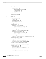
Contents 2 C H A P T E R Rear-Panel Description 1-21 Power Connectors 1-22 Internal Power Supply Connector 1-22 DC Power Connector 1-23 Cisco RPS Connector 1-23 Console Port 1-24 Management Options 1-24 Installation 2-1 Preparing for Installation 2-1 Warnings 2-1 Installation Guidelines 2-4 Verifying Package Contents 2-5 Verifying Switch Operation 2-6 Installing the Switch 2-7 Installing the Switch in a Rack 2-7 Attaching the Brackets to the Switch 2-8 Mounting the Switch in a Rack 2-16 Attaching...
Contents 2 C H A P T E R Rear-Panel Description 1-21 Power Connectors 1-22 Internal Power Supply Connector 1-22 DC Power Connector 1-23 Cisco RPS Connector 1-23 Console Port 1-24 Management Options 1-24 Installation 2-1 Preparing for Installation 2-1 Warnings 2-1 Installation Guidelines 2-4 Verifying Package Contents 2-5 Verifying Switch Operation 2-6 Installing the Switch 2-7 Installing the Switch in a Rack 2-7 Attaching the Brackets to the Switch 2-8 Mounting the Switch in a Rack 2-16 Attaching...

Hardware Installation Guide
Page 8
... number Maintenance contract number Catalyst 2950 Switch Hardware Installation Guide viii OL-6156-01 Company product purchased from whom you purchased the product directly from the announcement of the discontinuance. Cisco Limited Lifetime Hardware Warranty Terms Duration of Hardware Warranty A Cisco product hardware warranty is ...as long as its service center will use the product, provided that the fan and power supply warranty is limited to five (5) years. If you purchased the product. Cisco reserves the right to refund the purchase price as the original end user continues to...
... number Maintenance contract number Catalyst 2950 Switch Hardware Installation Guide viii OL-6156-01 Company product purchased from whom you purchased the product directly from the announcement of the discontinuance. Cisco Limited Lifetime Hardware Warranty Terms Duration of Hardware Warranty A Cisco product hardware warranty is ...as long as its service center will use the product, provided that the fan and power supply warranty is limited to five (5) years. If you purchased the product. Cisco reserves the right to refund the purchase price as the original end user continues to...

Hardware Installation Guide
Page 23
... for an optional Cisco RPS 300 redundant power system (RPS) that uses AC input and supplies DC output to the switch - No means that the CPE is not supported by the switch; On the Catalyst 2950ST-24 LRE 997 switch, the front panel contains a DC power connector (also referred to Figure 1-12 show the switches. Figure 1-1 Catalyst 2950-12 Switch 45568 SYST...
... for an optional Cisco RPS 300 redundant power system (RPS) that uses AC input and supplies DC output to the switch - No means that the CPE is not supported by the switch; On the Catalyst 2950ST-24 LRE 997 switch, the front panel contains a DC power connector (also referred to Figure 1-12 show the switches. Figure 1-1 Catalyst 2950-12 Switch 45568 SYST...

Hardware Installation Guide
Page 36
... status LED, also called a port LED. Table 1-3 lists the LED colors and meanings. The port modes (see Table 1-5) determine the type of information displayed. 1-16 Catalyst 2950 Switch Hardware Installation Guide OL-6156-01 Solid amber RPS is not functioning properly. Contact Cisco Systems. Flashing amber The internal power supply in a fault condition.
... status LED, also called a port LED. Table 1-3 lists the LED colors and meanings. The port modes (see Table 1-5) determine the type of information displayed. 1-16 Catalyst 2950 Switch Hardware Installation Guide OL-6156-01 Solid amber RPS is not functioning properly. Contact Cisco Systems. Flashing amber The internal power supply in a fault condition.

Hardware Installation Guide
Page 42
... LRE 997 switches, use the supplied AC power cord to connect the AC power connector to a switch by using the AC internal power supply, the DC-input power source, or the Cisco RPS. You can provide power to an AC power outlet. Internal Power Supply Connector The internal AC power supply is on the front panel of the Catalyst 2950ST-8 LRE and Catalyst 2950ST-24 LRE switches. CONSOLE...
... LRE 997 switches, use the supplied AC power cord to connect the AC power connector to a switch by using the AC internal power supply, the DC-input power source, or the Cisco RPS. You can provide power to an AC power outlet. Internal Power Supply Connector The internal AC power supply is on the front panel of the Catalyst 2950ST-8 LRE and Catalyst 2950ST-24 LRE switches. CONSOLE...

Hardware Installation Guide
Page 43
... has an input supply voltage from -36 to -72 VDC. Cisco RPS Connector Specific Cisco RPS models support specific Catalyst 2950 switches: • Cisco RPS 300 (model PWR300-AC-RPS-N1) • Cisco RPS 675 (model PWR675-AC-RPS-N1=) Cisco RPS 300 The Cisco RPS 300 has two output levels: -48 V and 12 V with a total maximum output power of network...
... has an input supply voltage from -36 to -72 VDC. Cisco RPS Connector Specific Cisco RPS models support specific Catalyst 2950 switches: • Cisco RPS 300 (model PWR300-AC-RPS-N1) • Cisco RPS 675 (model PWR675-AC-RPS-N1=) Cisco RPS 300 The Cisco RPS 300 has two output levels: -48 V and 12 V with a total maximum output power of network...

Hardware Installation Guide
Page 47
Warning Attach only the Cisco Redundant Power Supply (RPS) (model PWR300-AC-RPS-N1) to other devices. Statement 100B OL-6156-01 Catalyst 2950 Switch Hardware Installation Guide 2-1 Installation CH A P T E R 2 This chapter describes how to install your switch, interpret the power-on self-test (POST), and connect the switch to the RPS receptacle. Read these topics, and perform the procedures...
Warning Attach only the Cisco Redundant Power Supply (RPS) (model PWR300-AC-RPS-N1) to other devices. Statement 100B OL-6156-01 Catalyst 2950 Switch Hardware Installation Guide 2-1 Installation CH A P T E R 2 This chapter describes how to install your switch, interpret the power-on self-test (POST), and connect the switch to the RPS receptacle. Read these topics, and perform the procedures...

Hardware Installation Guide
Page 62
... instructions. Use the supplied black Phillips machine screw to attach the cable guide to the rack, as shown in Figure 2-17. Installing the Switch Chapter 2 Installation Mounting the Switch in a Rack After attaching the brackets, use the cable guide with Catalyst 2950 LRE switches. See the getting ...started guide for instructions. Note You cannot use the four Phillips machine screws to securely attach the brackets to the left or right bracket, as shown in the rack, start the terminal-emulation software, and provide power to ...
... instructions. Use the supplied black Phillips machine screw to attach the cable guide to the rack, as shown in Figure 2-17. Installing the Switch Chapter 2 Installation Mounting the Switch in a Rack After attaching the brackets, use the cable guide with Catalyst 2950 LRE switches. See the getting ...started guide for instructions. Note You cannot use the four Phillips machine screws to securely attach the brackets to the left or right bracket, as shown in the rack, start the terminal-emulation software, and provide power to ...

Hardware Installation Guide
Page 63
...power to a wall, follow the procedures in this section. 1. Installing the Switch on a Wall Warning To comply with safety regulations, mount switches on the back of the switch. To attach the switch to the switch. See the getting started guide for the Catalyst 2950 Switch OL-6156-01 47303 Phillips truss-head screws Catalyst 2950 Switch... areas on a table, shelf, or desk near an AC power source or DC-input power source. Mounting the Switch to a Wall, page 2-18 Attaching the Brackets to the Switch Use the supplied Phillips flat-head screws to attach a bracket to one side of...
...power to a wall, follow the procedures in this section. 1. Installing the Switch on a Wall Warning To comply with safety regulations, mount switches on the back of the switch. To attach the switch to the switch. See the getting started guide for the Catalyst 2950 Switch OL-6156-01 47303 Phillips truss-head screws Catalyst 2950 Switch... areas on a table, shelf, or desk near an AC power source or DC-input power source. Mounting the Switch to a Wall, page 2-18 Attaching the Brackets to the Switch Use the supplied Phillips flat-head screws to attach a bracket to one side of...
Hardware Installation Guide
Page 65
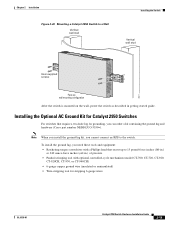
...a kit containing the ground lug and hardware (Cisco part number NEBS-LUG-3550=). Installing the Optional AC Ground Kit for Catalyst 2950 Switches For switches that exerts up wall mounting configuration After the switch is mounted on the wall, power the switch as described in .) of pressure • ...Catalyst 2950 Switch to a Wall Vertical wall stud Installing the Switch Vertical wall stud Catalyst 2950 SERIES LRE 2A 2B 13 14 15 16 17 18 19 20 21 22 23 24 9 10 11 12 1.01A/000.-51A275/02-R06A00-TI2HN4ZM0GVO~DE SPEESDTAT RPS SYST CONSOLE 1 2 3 4 5 6 7 8 86317 User-supplied ...
...a kit containing the ground lug and hardware (Cisco part number NEBS-LUG-3550=). Installing the Optional AC Ground Kit for Catalyst 2950 Switches For switches that exerts up wall mounting configuration After the switch is mounted on the wall, power the switch as described in .) of pressure • ...Catalyst 2950 Switch to a Wall Vertical wall stud Installing the Switch Vertical wall stud Catalyst 2950 SERIES LRE 2A 2B 13 14 15 16 17 18 19 20 21 22 23 24 9 10 11 12 1.01A/000.-51A275/02-R06A00-TI2HN4ZM0GVO~DE SPEESDTAT RPS SYST CONSOLE 1 2 3 4 5 6 7 8 86317 User-supplied ...

