
Hardware Installation Guide
Page 11
... organized into the following chapters: Chapter 1, "Product Overview," summarizes the switch features and describes the ports, the standards they support, and the LEDs. Chapter 3, "Troubleshooting," describes how to install a switch, and provides troubleshooting information and specifications. We assume that might arise when you are installing the switch. 78-6461-04 Catalyst 2900 Series XL Hardware Installation Guide xi Chapter 2, "Installation," provides the procedures for installing and configuring a Catalyst 2900 series XL switch.
... organized into the following chapters: Chapter 1, "Product Overview," summarizes the switch features and describes the ports, the standards they support, and the LEDs. Chapter 3, "Troubleshooting," describes how to install a switch, and provides troubleshooting information and specifications. We assume that might arise when you are installing the switch. 78-6461-04 Catalyst 2900 Series XL Hardware Installation Guide xi Chapter 2, "Installation," provides the procedures for installing and configuring a Catalyst 2900 series XL switch.

Hardware Installation Guide
Page 21
...-high-data-rate digital subscriber line (VDSL)-based technology that describe the Catalyst 2900 series XL switches, hereafter referred to as the switches. • Switch features, including management options • Descriptions of the front and rear panels • Descriptions of the LEDs Features The switches are stackable 10/100 Ethernet switches to which you can be deployed as servers, routers, and other network devices. The switches can connect workstations, Cisco...
...-high-data-rate digital subscriber line (VDSL)-based technology that describe the Catalyst 2900 series XL switches, hereafter referred to as the switches. • Switch features, including management options • Descriptions of the front and rear panels • Descriptions of the LEDs Features The switches are stackable 10/100 Ethernet switches to which you can be deployed as servers, routers, and other network devices. The switches can connect workstations, Cisco...

Hardware Installation Guide
Page 22
Catalyst 2900 Series XL Hardware Installation Guide 1-2 78-6461-04 Features Chapter 1 Product Overview • On the Catalyst 2924M XL, Catalyst 2912MF XL, and Catalyst 2924M XL DC switches, two module slots for 10BASE-T/100BASE-TX, 1000BASE-X, 1000BASE-T, Gigabit Ethernet, and asynchronous transfer mode (ATM) modules • On the Catalyst 2924M XL DC switch, a direct current (DC) power converter • On the Catalyst 2912 LRE XL and 2924 LRE...
Catalyst 2900 Series XL Hardware Installation Guide 1-2 78-6461-04 Features Chapter 1 Product Overview • On the Catalyst 2924M XL, Catalyst 2912MF XL, and Catalyst 2924M XL DC switches, two module slots for 10BASE-T/100BASE-TX, 1000BASE-X, 1000BASE-T, Gigabit Ethernet, and asynchronous transfer mode (ATM) modules • On the Catalyst 2924M XL DC switch, a direct current (DC) power converter • On the Catalyst 2912 LRE XL and 2924 LRE...

Hardware Installation Guide
Page 24
... switch front panels can have a set of LEDs and a Mode button. and port-level settings. • Command-line Interface (CLI)-The switch IOS CLI software is running platforms such as HP OpenView or SunNet Manager. You can fully configure and monitor a standalone switch, a specific cluster member, or an entire switch cluster. You can access the CLI either by connecting your network through a web browser such as CiscoWorks2000 LAN Management Suite (LMS) and HP OpenView. Catalyst 2900 Series XL Hardware Installation Guide...
... switch front panels can have a set of LEDs and a Mode button. and port-level settings. • Command-line Interface (CLI)-The switch IOS CLI software is running platforms such as HP OpenView or SunNet Manager. You can fully configure and monitor a standalone switch, a specific cluster member, or an entire switch cluster. You can access the CLI either by connecting your network through a web browser such as CiscoWorks2000 LAN Management Suite (LMS) and HP OpenView. Catalyst 2900 Series XL Hardware Installation Guide...

Hardware Installation Guide
Page 26
... high-speed workstations, Cisco IP Phones, servers, hubs, routers, and other switches through , twisted-pair cable. The 10/100 switch ports can be explicitly set for the cables are described in any compatible network device up to an AC power source. The 10/100 ports on the Catalyst 3524-PWR XL switch, refer to operate in Appendix B, "Connectors and Cable Specifications." These ports also can be set to the Catalyst 3500 Series XL Hardware Installation Guide...
... high-speed workstations, Cisco IP Phones, servers, hubs, routers, and other switches through , twisted-pair cable. The 10/100 switch ports can be explicitly set for the cables are described in any compatible network device up to an AC power source. The 10/100 ports on the Catalyst 3524-PWR XL switch, refer to operate in Appendix B, "Connectors and Cable Specifications." These ports also can be set to the Catalyst 3500 Series XL Hardware Installation Guide...

Hardware Installation Guide
Page 27
... the CPE devices without powering down the switch or disrupting the other switch ports. For information about the Cisco LRE CPE devices, refer to the Cisco LRE CPE Hardware Installation Guide. The splitter routes LRE data (high-frequency) and voice (low-frequency) traffic from the telephone line to private telephone networks and the public system telephone network 78-6461-04 Catalyst 2900 Series XL Hardware Installation Guide 1-7 Chapter 1 Product Overview Front...
... the CPE devices without powering down the switch or disrupting the other switch ports. For information about the Cisco LRE CPE devices, refer to the Cisco LRE CPE Hardware Installation Guide. The splitter routes LRE data (high-frequency) and voice (low-frequency) traffic from the telephone line to private telephone networks and the public system telephone network 78-6461-04 Catalyst 2900 Series XL Hardware Installation Guide 1-7 Chapter 1 Product Overview Front...

Hardware Installation Guide
Page 28
... is managed through the switch management interfaces. For more information about homologated POTS splitters, contact your Cisco sales representative. Table 1-1 Expansion Modules Module Type 10/100 Ethernet 100 BASE-FX Model Number WS-X2914-XL WS-X2914-XL-V WS-X2922-XL WS-X2922-XL-V WS-X2924-XL-V Catalyst 2900 Series XL Hardware Installation Guide 1-8 78-6461-04 Note If a connection to digital PBX switches that the module slots support. Front-Panel...
... is managed through the switch management interfaces. For more information about homologated POTS splitters, contact your Cisco sales representative. Table 1-1 Expansion Modules Module Type 10/100 Ethernet 100 BASE-FX Model Number WS-X2914-XL WS-X2914-XL-V WS-X2922-XL WS-X2922-XL-V WS-X2924-XL-V Catalyst 2900 Series XL Hardware Installation Guide 1-8 78-6461-04 Note If a connection to digital PBX switches that the module slots support. Front-Panel...

Hardware Installation Guide
Page 29
... MAC addresses), the module fails POST. The Ethernet Gigabit module supports several Gigabit Interface Converter (GBIC) devices. A power-on expansion modules for the Catalyst 2900 Series XL and Catalyst 3500 Series XL Switches. These modules automatically configure themselves when you install one of the LEDs and the Mode button that you use the switch LEDs to monitor switch activity and its performance. Refer to the Release Notes for Catalyst 2900 series XL switches. LEDs 78-6461-04 You can start the module by each port LED. Changing a port mode changes...
... MAC addresses), the module fails POST. The Ethernet Gigabit module supports several Gigabit Interface Converter (GBIC) devices. A power-on expansion modules for the Catalyst 2900 Series XL and Catalyst 3500 Series XL Switches. These modules automatically configure themselves when you install one of the LEDs and the Mode button that you use the switch LEDs to monitor switch activity and its performance. Refer to the Release Notes for Catalyst 2900 series XL switches. LEDs 78-6461-04 You can start the module by each port LED. Changing a port mode changes...

Hardware Installation Guide
Page 30
... member, on the CMS Cluster Manager window. Figure 1-5 Catalyst 2912 XL, 2924 XL, and 2924C XL LEDs 10/100 port LEDs System LED Port mode LEDs MODE 1X 2X 3X 4X 5X 6X 7X Mode RPS button LED 47288 1-10 Catalyst 2900 Series XL Hardware Installation Guide 78-6461-04 The Catalyst 2900 Series XL and Catalyst 3500 Series XL Software Configuration Guide describes how to use CMS to manage standalone or individual switches and how to use cluster management software to manage switch clusters].
... member, on the CMS Cluster Manager window. Figure 1-5 Catalyst 2912 XL, 2924 XL, and 2924C XL LEDs 10/100 port LEDs System LED Port mode LEDs MODE 1X 2X 3X 4X 5X 6X 7X Mode RPS button LED 47288 1-10 Catalyst 2900 Series XL Hardware Installation Guide 78-6461-04 The Catalyst 2900 Series XL and Catalyst 3500 Series XL Software Configuration Guide describes how to use CMS to manage standalone or individual switches and how to use cluster management software to manage switch clusters].

Hardware Installation Guide
Page 33
... connected. Table 1-3 RPS LED on the Catalyst 2912 XL, 2924C XL, 2924 XL, 2924MF XL, 2924M XL, and 2924M XL DC Switches Color Off Green Blinking green Amber RPS Status RPS is unavailable because it restarts. If the switch power supply fails, the switch powers down and after 15 seconds restarts, using power from the RPS. Pressing the Mode button on page 1-22. Refer to a neighboring device). 78-6461-04 Catalyst 2900 Series XL Hardware Installation Guide...
... connected. Table 1-3 RPS LED on the Catalyst 2912 XL, 2924C XL, 2924 XL, 2924MF XL, 2924M XL, and 2924M XL DC Switches Color Off Green Blinking green Amber RPS Status RPS is unavailable because it restarts. If the switch power supply fails, the switch powers down and after 15 seconds restarts, using power from the RPS. Pressing the Mode button on page 1-22. Refer to a neighboring device). 78-6461-04 Catalyst 2900 Series XL Hardware Installation Guide...

Hardware Installation Guide
Page 34
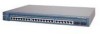
... 2924M XL DC Switches Mode LED STAT UTL FDUP 100 Port Mode Port status Switch utilization Port duplex mode Port speed Description The port status. Contact Cisco Systems. The internal power supply in use by the switch. (See Figure 1-8.) The port duplex mode: full duplex or half duplex, and default modes: • 10/100 ports: auto • 100BaseFX ports: auto • Gigabit ports: auto The port operating speed: 10 or 100 Mbps. 1-14 Catalyst 2900 Series XL Hardware Installation Guide 78-6461-04 The port modes (Table 1-4 and Table 1-5) determine the type of the 10/100...
... 2924M XL DC Switches Mode LED STAT UTL FDUP 100 Port Mode Port status Switch utilization Port duplex mode Port speed Description The port status. Contact Cisco Systems. The internal power supply in use by the switch. (See Figure 1-8.) The port duplex mode: full duplex or half duplex, and default modes: • 10/100 ports: auto • 100BaseFX ports: auto • Gigabit ports: auto The port operating speed: 10 or 100 Mbps. 1-14 Catalyst 2900 Series XL Hardware Installation Guide 78-6461-04 The port modes (Table 1-4 and Table 1-5) determine the type of the 10/100...
Hardware Installation Guide
Page 36
... XL DC Switches Port Mode STAT (port status) Port LED Color Off Solid green Flashing green Alternating green-amber Solid amber UTL Green (utilization) FDUP (port duplex) 100 (port speed) Off Green Off Green Meaning No link. Port is transmitting or receiving data. Note After a port is using less than 50 percent of its total capacity, and so on. Port is operating at 100 Mbps. 1-16 Catalyst 2900 Series XL Hardware Installation Guide 78-6461-04 Port was disabled by management or an address violation...
... XL DC Switches Port Mode STAT (port status) Port LED Color Off Solid green Flashing green Alternating green-amber Solid amber UTL Green (utilization) FDUP (port duplex) 100 (port speed) Off Green Off Green Meaning No link. Port is transmitting or receiving data. Note After a port is using less than 50 percent of its total capacity, and so on. Port is operating at 100 Mbps. 1-16 Catalyst 2900 Series XL Hardware Installation Guide 78-6461-04 Port was disabled by management or an address violation...
Hardware Installation Guide
Page 37
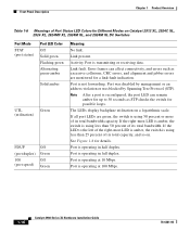
... port detects a connection to reflect Ethernet link status. See Table 1-5 for LED information about the 10/100 ports. Green LRE link present on the 10/100 ports. Cisco IOS Release 12.0(5.x)WC42 3 Cyan (off) Cyan (off) LRE port or remote CPE Ethernet port is administratively shut down . The Ethernet link default settings on the LRE ports are different from those on the LRE port. Blinking green Activity on the LRE port. Amber LRE port is in a non-STP forwarding...
... port detects a connection to reflect Ethernet link status. See Table 1-5 for LED information about the 10/100 ports. Green LRE link present on the 10/100 ports. Cisco IOS Release 12.0(5.x)WC42 3 Cyan (off) Cyan (off) LRE port or remote CPE Ethernet port is administratively shut down . The Ethernet link default settings on the LRE ports are different from those on the LRE port. Blinking green Activity on the LRE port. Amber LRE port is in a non-STP forwarding...

Hardware Installation Guide
Page 38
... Ethernet port is operating at 100 Mbps. 1. The Catalyst 2900 LRE XL switches do not support the Cisco 585 LRE CPE devices. 2. The LEDs on Catalyst 2900 LRE XL switches with this release or higher, use the Port Settings window or the show remote interfaces status user EXEC command. Front-Panel Description Chapter 1 Product Overview Table 1-7 Meanings of Port Status LEDs for Different Modes on Catalyst 2912 LRE XL and 2924 LRE XL Switches (continued) Port Mode SPEED Port LED...
... Ethernet port is operating at 100 Mbps. 1. The Catalyst 2900 LRE XL switches do not support the Cisco 585 LRE CPE devices. 2. The LEDs on Catalyst 2900 LRE XL switches with this release or higher, use the Port Settings window or the show remote interfaces status user EXEC command. Front-Panel Description Chapter 1 Product Overview Table 1-7 Meanings of Port Status LEDs for Different Modes on Catalyst 2912 LRE XL and 2924 LRE XL Switches (continued) Port Mode SPEED Port LED...

Hardware Installation Guide
Page 79
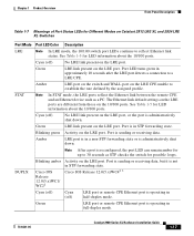
...). Follow these methods for the cables are described in no linkage. If the attached ports do not autonegotiate or that have their speed and duplex parameters manually set can explicitly set the speed and duplex parameters. Pinouts for configuring the 10/100 Ethernet ports: • Let the ports autonegotiate both speed and duplex. • Set the port speed and duplex parameters on page B-4. 78-6461-04 Catalyst 2900 Series XL Hardware Installation Guide 2-35
...). Follow these methods for the cables are described in no linkage. If the attached ports do not autonegotiate or that have their speed and duplex parameters manually set can explicitly set the speed and duplex parameters. Pinouts for configuring the 10/100 Ethernet ports: • Let the ports autonegotiate both speed and duplex. • Set the port speed and duplex parameters on page B-4. 78-6461-04 Catalyst 2900 Series XL Hardware Installation Guide 2-35
Hardware Installation Guide
Page 82
... then the port LED turns green. The port LED turns on , or there might be turned on when both Cisco 575 LRE CPE and Cisco 585 LRE CPE devices to connect each 100BASE-FX port. See Chapter 3, "Troubleshooting," for loops. Note You can hot swap the CPE devices without powering down the switch or disrupting the other end might not be a cable problem or a problem with the adapter installed in...
... then the port LED turns green. The port LED turns on , or there might be turned on when both Cisco 575 LRE CPE and Cisco 585 LRE CPE devices to connect each 100BASE-FX port. See Chapter 3, "Troubleshooting," for loops. Note You can hot swap the CPE devices without powering down the switch or disrupting the other end might not be a cable problem or a problem with the adapter installed in...
Hardware Installation Guide
Page 85
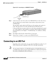
... LRE port status LED turns on when it establishes a link with the connector and cable assembly. If telephone services, such as voice or ISDN, use the same cabling as LRE traffic, the LRE port must be used. The splitter routes LRE data (high-frequency) and voice (low-frequency) traffic from the telephone line to private telephone networks and the PSTN. For more information about the Cisco LRE 48...
... LRE port status LED turns on when it establishes a link with the connector and cable assembly. If telephone services, such as voice or ISDN, use the same cabling as LRE traffic, the LRE port must be used. The splitter routes LRE data (high-frequency) and voice (low-frequency) traffic from the telephone line to private telephone networks and the PSTN. For more information about the Cisco LRE 48...

Hardware Installation Guide
Page 86
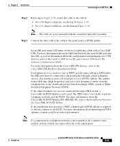
... that adapter from Cisco. or terminal-emulation software to a terminal. You can change the port baud rate to the switch console port. Follow these switch console port default characteristics: • 9600 baud • 8 data bits • 1 stop bit • No parity After you have accessed the switch, you want to connect the switch console port to communicate with the switch through hardware flow control. Connecting to a Module Port Chapter 2 Installation Connecting to a Module Port For information about installing and connecting to modules in the Catalyst 2924M XL...
... that adapter from Cisco. or terminal-emulation software to a terminal. You can change the port baud rate to the switch console port. Follow these switch console port default characteristics: • 9600 baud • 8 data bits • 1 stop bit • No parity After you have accessed the switch, you want to connect the switch console port to communicate with the switch through hardware flow control. Connecting to a Module Port Chapter 2 Installation Connecting to a Module Port For information about installing and connecting to modules in the Catalyst 2924M XL...
Hardware Installation Guide
Page 89
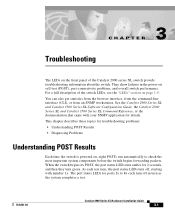
...), port-connectivity problems, and overall switch performance. When the switch begins its POST, the port status LEDs turn as the system completes a test. 78-6461-04 Catalyst 2900 Series XL Hardware Installation Guide 3-1 The port status LEDs for ports 2x to check the most important system components before the switch begins forwarding packets. See the Catalyst 2900 Series XL and Catalyst 3500 Series XL Software Configuration Guide, the Catalyst 2900 Series XL and Catalyst 3500 Series XL Command Reference, or the documentation that came with number 1x...
...), port-connectivity problems, and overall switch performance. When the switch begins its POST, the port status LEDs turn as the system completes a test. 78-6461-04 Catalyst 2900 Series XL Hardware Installation Guide 3-1 The port status LEDs for ports 2x to check the most important system components before the switch begins forwarding packets. See the Catalyst 2900 Series XL and Catalyst 3500 Series XL Software Configuration Guide, the Catalyst 2900 Series XL and Catalyst 3500 Series XL Command Reference, or the documentation that came with number 1x...
Hardware Installation Guide
Page 95
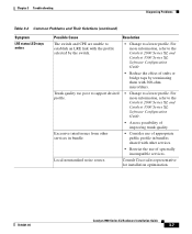
... Catalyst 3500 Series XL Software Configuration Guide • Reduce the effect of stubs or bridge taps by the switch. • Change to establish an LRE link with the profile selected by terminating them with other services in bundles shared with 300-ohm microfilters. Chapter 3 Troubleshooting Diagnosing Problems Table 3-2 Common Problems and Their Solutions (continued) Symptom LRE status LED stays amber. Excessive interference from other services. • Restrict the use...
... Catalyst 3500 Series XL Software Configuration Guide • Reduce the effect of stubs or bridge taps by the switch. • Change to establish an LRE link with the profile selected by terminating them with other services in bundles shared with 300-ohm microfilters. Chapter 3 Troubleshooting Diagnosing Problems Table 3-2 Common Problems and Their Solutions (continued) Symptom LRE status LED stays amber. Excessive interference from other services. • Restrict the use...

