
Users Manual - English
Page 33
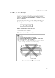
... cartridge contains enough toner to install the toner cartridge. 14 NO CARTRIDGE To install the toner cartridge, follow these steps: 1. Open the bag to print. Drum Shutter Fig. 2-9 Don'ts When Handling the Toner Cartridge 2-7 Caution • Do not expose the toner cartridge to direct light. • Do not ... message to prompt you turn it up-side down. • Do not touch the shaded parts shown below. • Do not open the drum shutter otherwise the toner or drum is set at about 5% coverage (if the print density is adversely affected and might cause serious damage when printing.
... cartridge contains enough toner to install the toner cartridge. 14 NO CARTRIDGE To install the toner cartridge, follow these steps: 1. Open the bag to print. Drum Shutter Fig. 2-9 Don'ts When Handling the Toner Cartridge 2-7 Caution • Do not expose the toner cartridge to direct light. • Do not ... message to prompt you turn it up-side down. • Do not touch the shaded parts shown below. • Do not open the drum shutter otherwise the toner or drum is set at about 5% coverage (if the print density is adversely affected and might cause serious damage when printing.
Users Manual - English
Page 201
... may result in labels peeling off and causing serious jam or print problems. All labels and transparencies used in this specification may stick to the drum or rollers and cause jams and print quality problems. No adhesive should not come in contact with an adhesive that are rough, highly textured, or...
... may result in labels peeling off and causing serious jam or print problems. All labels and transparencies used in this specification may stick to the drum or rollers and cause jams and print quality problems. No adhesive should not come in contact with an adhesive that are rough, highly textured, or...

Users Manual - English
Page 268
...: 2-3, 3-7 COPY switch: 4-77 cut sheet paper size: 4-23 D data compression: Appendix-49 DATA lamp: 4-4 data terminal ready: 4-19 demonstration pattern: 4-86 display: 4-1 download font: 4-39 drum shutter: 2-7 DTR: 4-19 duplex mode: 4-75 duplex printing: 4-75 duplex unit: 1-10, 3-11, 5-11 E ECONOMY switch: 4-69 emulation: 1-5 emulation mode: 3-1, 4-65 EMULATION switch: 4-65 envelope...
...: 2-3, 3-7 COPY switch: 4-77 cut sheet paper size: 4-23 D data compression: Appendix-49 DATA lamp: 4-4 data terminal ready: 4-19 demonstration pattern: 4-86 display: 4-1 download font: 4-39 drum shutter: 2-7 DTR: 4-19 duplex mode: 4-75 duplex printing: 4-75 duplex unit: 1-10, 3-11, 5-11 E ECONOMY switch: 4-69 emulation: 1-5 emulation mode: 3-1, 4-65 EMULATION switch: 4-65 envelope...

Service Manual
Page 4
... 1. IMAGE FORMATION SYSTEM II-5 3.1 Outline ...II-5 3.2 Printing Process ...II-5 3.2.1 Electrostatic latent image formation stage II-6 3.2.2 Developing stage II-8 3.2.3 Transfer stage II-9 3.2.4 Fixing stage II-10 3.2.5 Drum cleaning stage II-10 3.3 Operation ...II-11 4. CONTENTS CHAPTER I -1 3.
... 1. IMAGE FORMATION SYSTEM II-5 3.1 Outline ...II-5 3.2 Printing Process ...II-5 3.2.1 Electrostatic latent image formation stage II-6 3.2.2 Developing stage II-8 3.2.3 Transfer stage II-9 3.2.4 Fixing stage II-10 3.2.5 Drum cleaning stage II-10 3.3 Operation ...II-11 4. CONTENTS CHAPTER I -1 3.

Service Manual
Page 7
... and Radiological Health (CDRH). The printer is designed into a single assembly called an "EP-ED cartridge". F. The internally-storable, front-loading paper cassette enables you to carry. The charging roller, developing cylinder, photosensitive drum and cleaner of service call. Laser beam safety is approved by the multi-purpose paper feed tray and...
... and Radiological Health (CDRH). The printer is designed into a single assembly called an "EP-ED cartridge". F. The internally-storable, front-loading paper cassette enables you to carry. The charging roller, developing cylinder, photosensitive drum and cleaner of service call. Laser beam safety is approved by the multi-purpose paper feed tray and...

Service Manual
Page 8
... Separation Fixing Toner supply Life expectancy OPC Charging Roller Laser scanning system Toner projection development system Cassette or manual feed Roller method Natural(utilizing a small drum radius), Static charge eliminator Heated fixing roller Included in the replaceable EP-ED cartridge 6000 pages/cartridge (9) Paper Cassette feed Plain paper for Letter, Legal...
... Separation Fixing Toner supply Life expectancy OPC Charging Roller Laser scanning system Toner projection development system Cassette or manual feed Roller method Natural(utilizing a small drum radius), Static charge eliminator Heated fixing roller Included in the replaceable EP-ED cartridge 6000 pages/cartridge (9) Paper Cassette feed Plain paper for Letter, Legal...

Service Manual
Page 16
... the expiry may produce low-quality printing, so a cartridge should be handled carefully. 5.1 Storage of Unsealed EP-ED Cartridges Each EP-ED cartridge contains a photosensitive drum that is shown on the cartridge.) The expiry year and month (date of manufacture plus 2.5 years) is subject to vibration. 3) Do not hit or drop...
... the expiry may produce low-quality printing, so a cartridge should be handled carefully. 5.1 Storage of Unsealed EP-ED Cartridges Each EP-ED cartridge contains a photosensitive drum that is shown on the cartridge.) The expiry year and month (date of manufacture plus 2.5 years) is subject to vibration. 3) Do not hit or drop...

Service Manual
Page 17
... (SIMM) Font cartridge/card Optional I/O (MIO) Main PCB Delivery rollers Fixing unit Feeder External Device Control panel CONTROL SYSTEM IMAGE FORMATION SYSTEM Cleaning unit Photosensitive drum Developing unit Laser/scanner unit Transfer separation unit LASER/SCANNER SYSTEM MP tray PAPER PICK-UP/FEED SYSTEM Tray 1 Tray 2 (Option) Figure 2.1 II - 1 BASIC OPERATIONS...
... (SIMM) Font cartridge/card Optional I/O (MIO) Main PCB Delivery rollers Fixing unit Feeder External Device Control panel CONTROL SYSTEM IMAGE FORMATION SYSTEM Cleaning unit Photosensitive drum Developing unit Laser/scanner unit Transfer separation unit LASER/SCANNER SYSTEM MP tray PAPER PICK-UP/FEED SYSTEM Tray 1 Tray 2 (Option) Figure 2.1 II - 1 BASIC OPERATIONS...

Service Manual
Page 18
... controlled by the paper feed motor drive signal output from the main PCB. Figure 2.2 II - 2 Main motor Main motor drive signal (MDRIVE) Main PCB Drum gear Photosensitive drum Fixing unit Paper delivery rollers Paper feed motor Paper feed motor drive signal MP tray pick-up roller solenoid drive signal (MPSOL) MP tray...
... controlled by the paper feed motor drive signal output from the main PCB. Figure 2.2 II - 2 Main motor Main motor drive signal (MDRIVE) Main PCB Drum gear Photosensitive drum Fixing unit Paper delivery rollers Paper feed motor Paper feed motor drive signal MP tray pick-up roller solenoid drive signal (MPSOL) MP tray...
Service Manual
Page 20
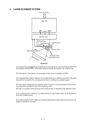
... laser beam is aligned into a parallel beam by the reflective mirror. As the photosensitive drum rotates at a constant speed and the laser beam scans the drum, an images is formed on the photosensitive drum via the focusing lenses arranged in the scanner unit generates a laser beam modulated by the... lens and then brought to the scanner unit. As the scanning mirror rotates at a constant speed, the laser beam scans the photosensitive drum at a constant speed. II - 4 The laser diode in front of the beam coming through the focusing lenses is rotating at a constant speed.
... laser beam is aligned into a parallel beam by the reflective mirror. As the photosensitive drum rotates at a constant speed and the laser beam scans the drum, an images is formed on the photosensitive drum via the focusing lenses arranged in the scanner unit generates a laser beam modulated by the... lens and then brought to the scanner unit. As the scanning mirror rotates at a constant speed, the laser beam scans the photosensitive drum at a constant speed. II - 4 The laser diode in front of the beam coming through the focusing lenses is rotating at a constant speed.

Service Manual
Page 21
...Then the toner image is contained in the cartridge, as a TVDO signal, forms a toner image on the photosensitive drum. The print information, after input from the video controller circuit into five major stages: Figure 2.6 1. The image formation system...OPC); Developing stage Step 3 Development Photoconductive layer Base II - 5 Laser beam Cartridge Primary charging roller Blade Cleaning blade Photosensitive drum Developing cylinder Paper Transfer charging roller Static charge eliminator Figure 2.5 The cartridge used by the transfer charging roller. 3. IMAGE FORMATION...
...Then the toner image is contained in the cartridge, as a TVDO signal, forms a toner image on the photosensitive drum. The print information, after input from the video controller circuit into five major stages: Figure 2.6 1. The image formation system...OPC); Developing stage Step 3 Development Photoconductive layer Base II - 5 Laser beam Cartridge Primary charging roller Blade Cleaning blade Photosensitive drum Developing cylinder Paper Transfer charging roller Static charge eliminator Figure 2.5 The cartridge used by the transfer charging roller. 3. IMAGE FORMATION...

Service Manual
Page 22
...Scanning charge exposure (step 1) (step 2) Unexposed area Transfer Primary (step 4) charge (step 1) Figure 2.8 II - 6 Primary charge Drum cleaning stage 7. Transfer Transfer stage Registration Cassette feed Multi-purpose tray feed Figure 2.7 3.2.1 Electrostatic latent image formation stage This stage has two... produce a pattern of negative charges on the photosensitive drum. Charges are absent from the "light" areas, where the laser beam struck (exposed) the drum surface. Drum cleaning stage Step 7 Drum cleaning Electrostatic latent image formation stage 2. Develop ment ...
...Scanning charge exposure (step 1) (step 2) Unexposed area Transfer Primary (step 4) charge (step 1) Figure 2.8 II - 6 Primary charge Drum cleaning stage 7. Transfer Transfer stage Registration Cassette feed Multi-purpose tray feed Figure 2.7 3.2.1 Electrostatic latent image formation stage This stage has two... produce a pattern of negative charges on the photosensitive drum. Charges are absent from the "light" areas, where the laser beam struck (exposed) the drum surface. Drum cleaning stage Step 7 Drum cleaning Electrostatic latent image formation stage 2. Develop ment ...

Service Manual
Page 23
..., etc., compared with the developing DC bias. In addition to DC bias, AC bias is applied to the photosensitive drum surface. Areas on the drum surface uniform. Step 2 Scanning exposure Laser beam ___ +++ Unexposed area Exposed area Figure 2.10 When the laser beam scans ...latent image. Step 1 Primary charge Primary charging roller AC bias DC bias Photosensitive drum Figure 2.9 As preparation for the primary charge. The printer uses the charging method that directly charges the drum for latent image formation, a uniform negative potential is applied to the primary charging...
..., etc., compared with the developing DC bias. In addition to DC bias, AC bias is applied to the photosensitive drum surface. Areas on the drum surface uniform. Step 2 Scanning exposure Laser beam ___ +++ Unexposed area Exposed area Figure 2.10 When the laser beam scans ...latent image. Step 1 Primary charge Primary charging roller AC bias DC bias Photosensitive drum Figure 2.9 As preparation for the primary charge. The printer uses the charging method that directly charges the drum for latent image formation, a uniform negative potential is applied to the primary charging...

Service Manual
Page 24
... visible. II - 8 Actually they are negative, but they are shown as positive. The developing cylinder rotates around a fixed internal magnet. Voltage (V) Developing cylinder surface potential +V 0 Drum surface potential (exposed area) DC bias -V Time t Drum surface potential (unexposed area) Figure 2.12 An AC bias is simplified by friction due to the laser beam have...
... visible. II - 8 Actually they are negative, but they are shown as positive. The developing cylinder rotates around a fixed internal magnet. Voltage (V) Developing cylinder surface potential +V 0 Drum surface potential (exposed area) DC bias -V Time t Drum surface potential (unexposed area) Figure 2.12 An AC bias is simplified by friction due to the laser beam have...

Service Manual
Page 25
...paper feed and prevent small white circles from appearing in sequence. The transfer charging roller is more stable. Step 5 Separation Photosensitive drum Paper Static charge eliminator Transfer charging roller Figure 2.14 The stiffness of the paper attracts the negatively charged toner particles to the... transfer charging roller. 3.2.3 Transfer stage In the transfer stage, the toner image is transferred from the drum surface to the drum. II - 9 Advantages compared with the corona transfer method are as follows: • Low transfer voltage that is less ...
...paper feed and prevent small white circles from appearing in sequence. The transfer charging roller is more stable. Step 5 Separation Photosensitive drum Paper Static charge eliminator Transfer charging roller Figure 2.14 The stiffness of the paper attracts the negatively charged toner particles to the... transfer charging roller. 3.2.3 Transfer stage In the transfer stage, the toner image is transferred from the drum surface to the drum. II - 9 Advantages compared with the corona transfer method are as follows: • Low transfer voltage that is less ...

Service Manual
Page 26
... 2.15 The upper roller surface is fixed by the cleaning blade to make a permanent image. II - 10 This residual toner is cleaned off in the drum cleaning stage so that of the lower roller, resulting in the cleaner container. The removed toner is collected in the toner being drawn to the... lower roller, and adhering to the lower roller surface. 3.2.5 Drum cleaning stage In the transfer stage, not all the toner is scraped away by heating the paper and applying pressure. Step...
... 2.15 The upper roller surface is fixed by the cleaning blade to make a permanent image. II - 10 This residual toner is cleaned off in the drum cleaning stage so that of the lower roller, resulting in the cleaner container. The removed toner is collected in the toner being drawn to the... lower roller, and adhering to the lower roller surface. 3.2.5 Drum cleaning stage In the transfer stage, not all the toner is scraped away by heating the paper and applying pressure. Step...

Service Manual
Page 27
... also has a toner sensor. The latent image formed on the drum surface is converted into a visible image by a DATA signal scans the drum surface to rotate the photosensitive drum. When the output from the drum surface with an alarm. After the drum surface is charged negatively by the primary charge roller, the laser ...beam modulated by the toner on the drum. 3.3 Operation When the engine controller circuit receives a print signal (PRINT) or a pre-feed signal (PRFD) from the video controller circuit, the engine controller ...
... also has a toner sensor. The latent image formed on the drum surface is converted into a visible image by a DATA signal scans the drum surface to rotate the photosensitive drum. When the output from the drum surface with an alarm. After the drum surface is charged negatively by the primary charge roller, the laser ...beam modulated by the toner on the drum. 3.3 Operation When the engine controller circuit receives a print signal (PRINT) or a pre-feed signal (PRFD) from the video controller circuit, the engine controller ...

Service Manual
Page 28
... is deliveried to the face down to the circuit while the paper feed motor is rotating, the paper pick-up solenoid comes on the photosensitive drum. if printed paper has not reached or not cleared the paper ejection sensor in a specified time, the printer judges that the leading edge of ...the image on and the paper pick-up roller solenoid drive signal (PUCL1) is input to the photosensitive drum. After this case a paper jam is detected by the registration sensor so that a paper jam has occurred. MP tray paper empty sensor signal (PEMP) MP...
... is deliveried to the face down to the circuit while the paper feed motor is rotating, the paper pick-up solenoid comes on the photosensitive drum. if printed paper has not reached or not cleared the paper ejection sensor in a specified time, the printer judges that the leading edge of ...the image on and the paper pick-up roller solenoid drive signal (PUCL1) is input to the photosensitive drum. After this case a paper jam is detected by the registration sensor so that a paper jam has occurred. MP tray paper empty sensor signal (PEMP) MP...

Service Manual
Page 29
... motor Registration sensor Paper ejection sensor Pick-up one rotation. When the engine controller circuit receives PRNT or PRFD signal from flashing to the photosensitive drum. This feeds paper to lighting. Timing chart for the pick-up roller solenoid 2.3 sec 4.24 sec 2.90 sec 0.2 sec 0.2 sec Figure 2.19 II - 13...
... motor Registration sensor Paper ejection sensor Pick-up one rotation. When the engine controller circuit receives PRNT or PRFD signal from flashing to the photosensitive drum. This feeds paper to lighting. Timing chart for the pick-up roller solenoid 2.3 sec 4.24 sec 2.90 sec 0.2 sec 0.2 sec Figure 2.19 II - 13...

Service Manual
Page 78
... too thick or too thin, or tends to curl, paper jams or paper feed problems may occur, or prints may be light. 2) If the photosensitive drum is cold, the electrical resistance of the photosensitive layer gets high, making it impossible to obtain a correct contrast in the printer . [If the message is...
... too thick or too thin, or tends to curl, paper jams or paper feed problems may occur, or prints may be light. 2) If the photosensitive drum is cold, the electrical resistance of the photosensitive layer gets high, making it impossible to obtain a correct contrast in the printer . [If the message is...


