
U8568 Pro user's manual
Page 2
... Hard Disk Connectors: IDE1/IDE2 4-4. Notice Mainboard Features 1. System Fan Header: JSFAN1 4. Front USB Header: JUSB3 4-8. Front USB Header: JUSB4 4-9. 5V / 5VSB Selection for KB: JKBV1 CPU Configuration 3-1. Component Index 3. Jumpers, Headers & Connectors 4-1. BIOS & Software 1-3. CPU Fan Header: JCFAN1 3-3. ATX 20-pin Power Connector: JATXPWR1 4-3. Package Contents 2. CPU Socket 478 Configuration Steps: 3-2. Mainboard Configuration 2-1. Layout of U8568 Pro 2-2. Front Panel Connector: JPANEL1 4-2. Floppy Disk Connector: FDD1 4-5. Wake On LAN Header...
... Hard Disk Connectors: IDE1/IDE2 4-4. Notice Mainboard Features 1. System Fan Header: JSFAN1 4. Front USB Header: JUSB3 4-8. Front USB Header: JUSB4 4-9. 5V / 5VSB Selection for KB: JKBV1 CPU Configuration 3-1. Component Index 3. Jumpers, Headers & Connectors 4-1. BIOS & Software 1-3. CPU Fan Header: JCFAN1 3-3. ATX 20-pin Power Connector: JATXPWR1 4-3. Package Contents 2. CPU Socket 478 Configuration Steps: 3-2. Mainboard Configuration 2-1. Layout of U8568 Pro 2-2. Front Panel Connector: JPANEL1 4-2. Floppy Disk Connector: FDD1 4-5. Wake On LAN Header...

U8568 Pro user's manual
Page 3
... 5. PS/2 Mouse / Keyboard Connector: JKBMS1 6-2. Audio Subsystem WarpSpeeder Introduction System Requirement Installation Usage RAM Module Configuration 5-1. How to install DDR/SDRAM DIMM Module 6. Game (Joystick/MIDI) Port Connector: JAUD_GAME 6-5. Front 1394 Header: J1394C1(Optional) 4-17. Audio Port Connectors: JSPKR1/JLIN1/JMIC1 6-6. ATX 12V Power Connector: JATXPWR2 4-11. 5V / 5VSB Selection for USB: JUSBV1 4-12. 5V / 5VSB Selection for USB: JUSBV3 4-13. 5V / 5VSB Selection for USB: JUSBV4 4-14. USB & LAN Port Connectors: JUSBLAN1 6-3. 4-10...
... 5. PS/2 Mouse / Keyboard Connector: JKBMS1 6-2. Audio Subsystem WarpSpeeder Introduction System Requirement Installation Usage RAM Module Configuration 5-1. How to install DDR/SDRAM DIMM Module 6. Game (Joystick/MIDI) Port Connector: JAUD_GAME 6-5. Front 1394 Header: J1394C1(Optional) 4-17. Audio Port Connectors: JSPKR1/JLIN1/JMIC1 6-6. ATX 12V Power Connector: JATXPWR2 4-11. 5V / 5VSB Selection for USB: JUSBV1 4-12. 5V / 5VSB Selection for USB: JUSBV3 4-13. 5V / 5VSB Selection for USB: JUSBV4 4-14. USB & LAN Port Connectors: JUSBLAN1 6-3. 4-10...

U8568 Pro user's manual
Page 5
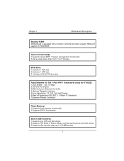
...: VT8235/ VT8233A. Features Introduction 1-1. Chipset - ITE IT8705. 1.Supports 200MHz, 266MHz DDR SDRAM or PC100, PC133 SDRAM. 2.Supports 64Mb, 128Mb, 256Mb and 512Mb technologies for high-end workstations and servers. 1.Runing at 400/ 533 MHz Front Side Bus frequency. 2.Supports up to 2.8 GHz CPU core speeds. 3.The 33MHz 32 bit PCI 2.2 compliant. 4.The 66MHz AGP 2.0 compliant interface supports 1x, 2x and 4x data transfer mode. Mainboard Features 1. Chipset -
...: VT8235/ VT8233A. Features Introduction 1-1. Chipset - ITE IT8705. 1.Supports 200MHz, 266MHz DDR SDRAM or PC100, PC133 SDRAM. 2.Supports 64Mb, 128Mb, 256Mb and 512Mb technologies for high-end workstations and servers. 1.Runing at 400/ 533 MHz Front Side Bus frequency. 2.Supports up to 2.8 GHz CPU core speeds. 3.The 33MHz 32 bit PCI 2.2 compliant. 4.The 66MHz AGP 2.0 compliant interface supports 1x, 2x and 4x data transfer mode. Mainboard Features 1. Chipset -
U8568 Pro user's manual
Page 6
...Ethernet Controller. 4.Optional Repeater Interface. 5.Auto Negotiation: 10/ 100, Full/ Half Duplex. 6.Meet All Applicable IEEE 802.3, 10Base-Tx Standards. 7.Baseline Wander Correction. 1.Supports flash memory functionality. 2.Supports ESCD functionality. 1.Supports four IDE hard disk drives. 2.Supports PIO Mode 4, Master Mode, and high performance hard disk drives. 3.Supports disk transfer rates up to 15 minutes. 1.Contains 1 AGP slot. 2.Contains 1 CNR slot. 3. Motherboard is equipped with a memory controller providing shadow RAM and support for ROM BIOS. 1.Supports Award BIOS ™ power...
...Ethernet Controller. 4.Optional Repeater Interface. 5.Auto Negotiation: 10/ 100, Full/ Half Duplex. 6.Meet All Applicable IEEE 802.3, 10Base-Tx Standards. 7.Baseline Wander Correction. 1.Supports flash memory functionality. 2.Supports ESCD functionality. 1.Supports four IDE hard disk drives. 2.Supports PIO Mode 4, Master Mode, and high performance hard disk drives. 3.Supports disk transfer rates up to 15 minutes. 1.Contains 1 AGP slot. 2.Contains 1 CNR slot. 3. Motherboard is equipped with a memory controller providing shadow RAM and support for ROM BIOS. 1.Supports Award BIOS ™ power...
U8568 Pro user's manual
Page 7
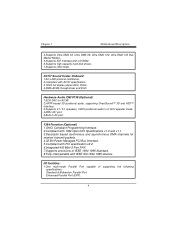
... 133 Bus Master Modes. 5.Supports IDE interface with CD-ROM. 6.Supports high capacity hard disk drives. 7.Supports LBA mode. 1.AC-LINK protocol comfliance. 2.Compliant with AC'97 specification. 3.18-bit full duplex stereo ADC, DACs. 4.SNR>95 Bb throughmixer and DAC. 1.6CH DAC for AC3®. 2.HRTF-based 3D positional audio, supporting DirectSound™ 3D and A3D™ interface. 3.Supports 4.1/ 5.1 speakers, C3DX positional audio in 4/ 6CH speaker mode. 4.MPU-401 port. 5.Built...
... 133 Bus Master Modes. 5.Supports IDE interface with CD-ROM. 6.Supports high capacity hard disk drives. 7.Supports LBA mode. 1.AC-LINK protocol comfliance. 2.Compliant with AC'97 specification. 3.18-bit full duplex stereo ADC, DACs. 4.SNR>95 Bb throughmixer and DAC. 1.6CH DAC for AC3®. 2.HRTF-based 3D positional audio, supporting DirectSound™ 3D and A3D™ interface. 3.Supports 4.1/ 5.1 speakers, C3DX positional audio in 4/ 6CH speaker mode. 4.MPU-401 port. 5.Built...

U8568 Pro user's manual
Page 8
Supports two back panel Universal Serial Bus (USB1.1) Ports and two front panel Universal Serial Bus (USB1.1) Ports. 1.Monitors CPU Fan Speed. 2.Monitors System Voltage. 3.Monitors System Speed. 24.5cm x 29.5cm (WxL) Normal 2.Supports one serial port, 16550 UART. 3.Supports Infrared Data Transmission using IrDA. 4.Supports PS/2 mouse and PS/2 keyboard. 5.Supports 360KB, 720KB, 1.2MB, 1.44MB, and 2.88MB floppy disk drives. Extended Capabilities Port (ECP). Supports two back panel Universal Serial Bus (USB2.0) Ports and four front panel Universal Serial Bus (USB2.0) Ports.
Supports two back panel Universal Serial Bus (USB1.1) Ports and two front panel Universal Serial Bus (USB1.1) Ports. 1.Monitors CPU Fan Speed. 2.Monitors System Voltage. 3.Monitors System Speed. 24.5cm x 29.5cm (WxL) Normal 2.Supports one serial port, 16550 UART. 3.Supports Infrared Data Transmission using IrDA. 4.Supports PS/2 mouse and PS/2 keyboard. 5.Supports 360KB, 720KB, 1.2MB, 1.44MB, and 2.88MB floppy disk drives. Extended Capabilities Port (ECP). Supports two back panel Universal Serial Bus (USB2.0) Ports and four front panel Universal Serial Bus (USB2.0) Ports.
U8568 Pro user's manual
Page 9
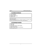
Package Contents 1.HDD Cable. 2.FDD Cable. 3.Flash Memory Writer for BIOS Update. 4.USB Cable (Optional). 5.Rear I/O Panel for MS-DOS, Windows NT, Windows 2000, Windows ME, Windows XP, Novell, LINUX, and SCO UNIX etc. 1-3. Offers the highest performance for MATX Case (Optional). 6.Fully Setup Driver CD. 1-2. BIOS & Software 1.Award legal BIOS. 2.Supports APM1.2. 3.Supports USB Function. 4.Supports ACPI.
Package Contents 1.HDD Cable. 2.FDD Cable. 3.Flash Memory Writer for BIOS Update. 4.USB Cable (Optional). 5.Rear I/O Panel for MS-DOS, Windows NT, Windows 2000, Windows ME, Windows XP, Novell, LINUX, and SCO UNIX etc. 1-3. Offers the highest performance for MATX Case (Optional). 6.Fully Setup Driver CD. 1-2. BIOS & Software 1.Award legal BIOS. 2.Supports APM1.2. 3.Supports USB Function. 4.Supports ACPI.
U8568 Pro user's manual
Page 10
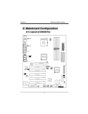
2. Layout of U8568 Pro Mainboard Configuration 2-1.
2. Layout of U8568 Pro Mainboard Configuration 2-1.

U8568 Pro user's manual
Page 12
Pull the lever sideways away from the socket then raise the lever up to complete the installation. Match Pin A with the white dot/cut edge in the socket and look for the white dot or cut edge then insert the CPU. 3. 3. Locate Pin A in the CPU. Press the lever down. Then Put the fan on the CPU and buckle it and put the fan's power port into the JCFAN1, then to a 90-degree angle. 2. CPU Socket 478 Configuration Steps: CPU Fan CPU 1. CPU Configuration 3-1.
Pull the lever sideways away from the socket then raise the lever up to complete the installation. Match Pin A with the white dot/cut edge in the socket and look for the white dot or cut edge then insert the CPU. 3. 3. Locate Pin A in the CPU. Press the lever down. Then Put the fan on the CPU and buckle it and put the fan's power port into the JCFAN1, then to a 90-degree angle. 2. CPU Socket 478 Configuration Steps: CPU Fan CPU 1. CPU Configuration 3-1.
U8568 Pro user's manual
Page 16
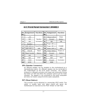
... 2 Sleep Control Sleep 3 NA Speaker 4 Ground Button 5 NA Connector 6 NA NA 7 Speaker 8 Power LED (+) 9 HDD LED (+) Hard Drive 10 Power LED (+) POWER 11 HDD LED (-) LED 12 Power LED (-) LED 13 Ground Reset 14 Power Button Power-on 15 Reset Control Button 16 Ground Button 17 NA 18 KEY 19 NA IrDA 20 KEY IrDA 21 VCC5 Connector 22 Ground Connector 23 IRTX 24 IRRX SPK (Speaker Connector) An offboard speaker can be connected to reset and run the POST (Power On Self Test). RST (Reset Button) This connector can be installed on the motherboard as...
... 2 Sleep Control Sleep 3 NA Speaker 4 Ground Button 5 NA Connector 6 NA NA 7 Speaker 8 Power LED (+) 9 HDD LED (+) Hard Drive 10 Power LED (+) POWER 11 HDD LED (-) LED 12 Power LED (-) LED 13 Ground Reset 14 Power Button Power-on 15 Reset Control Button 16 Ground Button 17 NA 18 KEY 19 NA IrDA 20 KEY IrDA 21 VCC5 Connector 22 Ground Connector 23 IRTX 24 IRRX SPK (Speaker Connector) An offboard speaker can be connected to reset and run the POST (Power On Self Test). RST (Reset Button) This connector can be installed on the motherboard as...
U8568 Pro user's manual
Page 17
... to this option, you need to connect a button from portable devices such as laptops, PDAs is depressed again. IR (Infrared Connector) This connector is used to conserve energy by powering down the monitor and hard drives until the system is invoked by any keyboard activity, mouse activity, modem activity or when the sleep button is possible. To configure this connector. The switch must pull the Power Button pin to ground...
... to this option, you need to connect a button from portable devices such as laptops, PDAs is depressed again. IR (Infrared Connector) This connector is used to conserve energy by powering down the monitor and hard drives until the system is invoked by any keyboard activity, mouse activity, modem activity or when the sleep button is possible. To configure this connector. The switch must pull the Power Button pin to ground...
U8568 Pro user's manual
Page 18
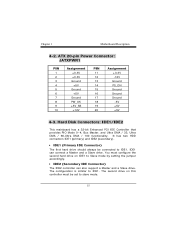
... to slave mode. It has two HDD connectors IDE1 (primary) and IDE2 (secondary). • IDE1 (Primary IDE Connector) The first hard drive should always be set to Slave mode by setting the jumper accordingly. • IDE2 (Secondary IDE Connector) The IDE2 controller can connect a Master and a Slave drive. The configuration is similar to IDE1. 4-2. You must configure the second hard drive on this controller must be connected to IDE1. ATX 20-pin Power Connector: JATXPWR1 PIN 1 2 3 4 5 6 7 8 9 10...
... to slave mode. It has two HDD connectors IDE1 (primary) and IDE2 (secondary). • IDE1 (Primary IDE Connector) The first hard drive should always be set to Slave mode by setting the jumper accordingly. • IDE2 (Secondary IDE Connector) The IDE2 controller can connect a Master and a Slave drive. The configuration is similar to IDE1. 4-2. You must configure the second hard drive on this controller must be connected to IDE1. ATX 20-pin Power Connector: JATXPWR1 PIN 1 2 3 4 5 6 7 8 9 10...
U8568 Pro user's manual
Page 19
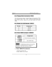
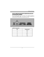
Wake On LAN Header: JWOL1 Pin No. 1 2 3 Assignment +5V SB Ground Wake up 4-6. This connector supports the provided floppy drive ribbon cables. 4-5. Remove AC power line. 2. 4-4. Floppy Disk Connector: FDD1 The motherboard provides a standard floppy disk connector (FDC) that supports 360K, 720K, 1.2M, 1.44M and 2.88M floppy disk types. Clear CMOS Jumper: JCMOS1 JCMOS1 1 3 1-2 Closed 1 3 2-3 Closed Assignment Normal Operation (default) Clear CMOS Data Clear CMOS Procedures: 1. Make JCMOS1 (2-3) closed.
Wake On LAN Header: JWOL1 Pin No. 1 2 3 Assignment +5V SB Ground Wake up 4-6. This connector supports the provided floppy drive ribbon cables. 4-5. Remove AC power line. 2. 4-4. Floppy Disk Connector: FDD1 The motherboard provides a standard floppy disk connector (FDC) that supports 360K, 720K, 1.2M, 1.44M and 2.88M floppy disk types. Clear CMOS Jumper: JCMOS1 JCMOS1 1 3 1-2 Closed 1 3 2-3 Closed Assignment Normal Operation (default) Clear CMOS Data Clear CMOS Procedures: 1. Make JCMOS1 (2-3) closed.
U8568 Pro user's manual
Page 20
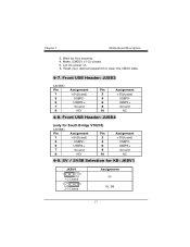
Reset your desired password or clear the CMOS data. 4-7. 3. Make JCMOS1 (1-2) closed. 5. Front USB Header: JUSB3 (JUSB3) Pin 1 3 5 7 9 Assignment +5V(fused) USBP2USBP2+ Ground KEY Pin Assignment 2 +5V(fused) 4 USBP3- 6 USBP3+ 8 Ground 10 NC 4-8. Front USB Header: JUSB4 (JUSB4) Pin 1 3 5 7 9 Assignment +5V(fused) USBP2USBP2+ Ground KEY Pin Assignment 2 +5V(fused) 4 USBP3- 6 USBP3+ 8 Ground 10 NC 4-9. 5V / 5VSB Selection for five seconds. 4. Let AC power on. 6. Wait for KB: JKBV1 JKBV1 Assignment
Reset your desired password or clear the CMOS data. 4-7. 3. Make JCMOS1 (1-2) closed. 5. Front USB Header: JUSB3 (JUSB3) Pin 1 3 5 7 9 Assignment +5V(fused) USBP2USBP2+ Ground KEY Pin Assignment 2 +5V(fused) 4 USBP3- 6 USBP3+ 8 Ground 10 NC 4-8. Front USB Header: JUSB4 (JUSB4) Pin 1 3 5 7 9 Assignment +5V(fused) USBP2USBP2+ Ground KEY Pin Assignment 2 +5V(fused) 4 USBP3- 6 USBP3+ 8 Ground 10 NC 4-9. 5V / 5VSB Selection for five seconds. 4. Let AC power on. 6. Wait for KB: JKBV1 JKBV1 Assignment
U8568 Pro user's manual
Page 25
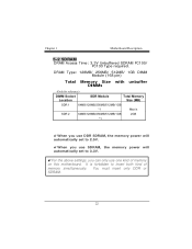
You must insert only DDR or SDRAM. 5-2 SDRAM DRAM Access Time: 3.3V Unbuffered SDRAM PC100/ PC133 Type required. It is forbidden to 3.3V. !For the above settings, you can only use one kind of memory simultaneously. DRAM Type: 128MB/ 256MB/ 512MB/ 1GB DIMM Module (168 pin) Total Memory Size with unbuffer DIMMs !When you use DDR SDRAM, the memory power will automatically set to 2.5V. !When you use SDRAM, the memory power will automatically set to insert both kind of memory on this motherboard.
You must insert only DDR or SDRAM. 5-2 SDRAM DRAM Access Time: 3.3V Unbuffered SDRAM PC100/ PC133 Type required. It is forbidden to 3.3V. !For the above settings, you can only use one kind of memory simultaneously. DRAM Type: 128MB/ 256MB/ 512MB/ 1GB DIMM Module (168 pin) Total Memory Size with unbuffer DIMMs !When you use DDR SDRAM, the memory power will automatically set to 2.5V. !When you use SDRAM, the memory power will automatically set to insert both kind of memory on this motherboard.
U8568 Pro user's manual
Page 28
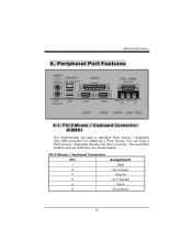
... / Keyboard directly into this connector. Peripheral Port Features JKBMS1 PS/2 JUSBLAN1 Mouse LAN (Optional) JPRNT1 Parallel JAUD_GAME Game Port PS/2 Keyboard USB COM1 COM2 Speaker Line In Mic Out In JCOM1 JCOM2 JSPKR1 JLIN1 JMIC1 6-1. The connector location and pin definition are shown below: PS/2 Mouse / Keyboard Connectors Pin 1 2 3 4 5 6 Assignment Data No connect Ground +5 V (fused) Clock No connect 6. PS/2 Mouse / Keyboard Connector: JKBMS1 The motherboard provides a standard PS/2 mouse / Keyboard mini DIN connector...
... / Keyboard directly into this connector. Peripheral Port Features JKBMS1 PS/2 JUSBLAN1 Mouse LAN (Optional) JPRNT1 Parallel JAUD_GAME Game Port PS/2 Keyboard USB COM1 COM2 Speaker Line In Mic Out In JCOM1 JCOM2 JSPKR1 JLIN1 JMIC1 6-1. The connector location and pin definition are shown below: PS/2 Mouse / Keyboard Connectors Pin 1 2 3 4 5 6 Assignment Data No connect Ground +5 V (fused) Clock No connect 6. PS/2 Mouse / Keyboard Connector: JKBMS1 The motherboard provides a standard PS/2 mouse / Keyboard mini DIN connector...
U8568 Pro user's manual
Page 30
6-2-2. You can set up the connection by entering account information provided by your ISP. LAN Port Connector Pin 9 10 11 12 13 14 Assignment VCC3 TD+ TDRD+ RDNC LAN Port Connector (Optional) (only for South Bridge VT8235) This connector allows you to connect to the Internet through a Local Area Network (LAN).
6-2-2. You can set up the connection by entering account information provided by your ISP. LAN Port Connector Pin 9 10 11 12 13 14 Assignment VCC3 TD+ TDRD+ RDNC LAN Port Connector (Optional) (only for South Bridge VT8235) This connector allows you to connect to the Internet through a Local Area Network (LAN).
U8568 Pro user's manual
Page 31
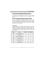
... Send Clear to as an RS-232 port or an asynchronous communication port. Mice, printers, modems and other peripheral devices can also be used when configuring certain software programs to connect your computer with one serial port and one parallel port. Both types of the 25-pin connector. The serial port can be explained in many ways, and it may be used to work with the pinout diagram. 6-3. The Serial Interface...
... Send Clear to as an RS-232 port or an asynchronous communication port. Mice, printers, modems and other peripheral devices can also be used when configuring certain software programs to connect your computer with one serial port and one parallel port. Both types of the 25-pin connector. The serial port can be explained in many ways, and it may be used to work with the pinout diagram. 6-3. The Serial Interface...
U8568 Pro user's manual
Page 36
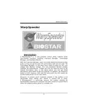
... then restart to a speed that is not appropriate when testing and results in the About panel, you can get detail descriptions about BIOS model and chipsets. Moreover, to power up CPU core voltage and Memory voltage. WarpSpeeder Introduction [ WarpSpeeder™ ], a new powerful control utility, features three user-friendly functions including Overclock Manager, Overvoltage Manager, and Hardware Monitor. In addition, the frequency status of CPU, memory, AGP and PCI along with just...
... then restart to a speed that is not appropriate when testing and results in the About panel, you can get detail descriptions about BIOS model and chipsets. Moreover, to power up CPU core voltage and Memory voltage. WarpSpeeder Introduction [ WarpSpeeder™ ], a new powerful control utility, features three user-friendly functions including Overclock Manager, Overvoltage Manager, and Hardware Monitor. In addition, the frequency status of CPU, memory, AGP and PCI along with just...
U8568 Pro user's manual
Page 42
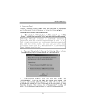
... frequency automatically. [ WarpSpeeder™ ] utility will slide out to do fail-safe reboot by click the Verify button. Let user select a restoring way if system need to the hardware default setting or load the verified best and c. Overclock Panel Click the Overclock button in Main Panel, the button will be highlighted and the Overclock Panel will execute a series of testing until system fail. "-3MHz button", "-1MHz button", "+1MHz button", and "+3MHz button...
... frequency automatically. [ WarpSpeeder™ ] utility will slide out to do fail-safe reboot by click the Verify button. Let user select a restoring way if system need to the hardware default setting or load the verified best and c. Overclock Panel Click the Overclock button in Main Panel, the button will be highlighted and the Overclock Panel will execute a series of testing until system fail. "-3MHz button", "-1MHz button", "+1MHz button", and "+3MHz button...


