

TForce4 SLI user's manual
Page 2
... ...14 CHAPTER 4: NVIDIA RAID FUNCTIONS ...15 4.1 OPERATION SYSTEM ...15 4.2 RAID ARRAYS ...15 4.3 HOW RAID WORKS ...15 ii User's Manual DDR Modules ...4 B. Card and I CHAPTER 1: INTRODUCTION ...1 1.1 MOTHERBOARD FEATURES ...1 1.2 LAYOUT AND COMPONENTS ...2 CHAPTER 2: HARDWARE INSTALLATIONS ...3 2.1 CPU ASSEMBLY ...3 A. Biostar T-Series TForce4 SLI PACKAGE CHECKLIST ...I /O Slots:...5 B. Know your CPU Version ...4 2.3 PERIPHERALS ...5 A.
... ...14 CHAPTER 4: NVIDIA RAID FUNCTIONS ...15 4.1 OPERATION SYSTEM ...15 4.2 RAID ARRAYS ...15 4.3 HOW RAID WORKS ...15 ii User's Manual DDR Modules ...4 B. Card and I CHAPTER 1: INTRODUCTION ...1 1.1 MOTHERBOARD FEATURES ...1 1.2 LAYOUT AND COMPONENTS ...2 CHAPTER 2: HARDWARE INSTALLATIONS ...3 2.1 CPU ASSEMBLY ...3 A. Biostar T-Series TForce4 SLI PACKAGE CHECKLIST ...I /O Slots:...5 B. Know your CPU Version ...4 2.3 PERIPHERALS ...5 A.
TForce4 SLI user's manual
Page 4
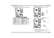
... Supports NVIDIA Secure Networking Processor. Three PCI-Express x1 slots: PEX16-2, PEX1-1 and PEX1-2. Notice: Normal Mode and SLI Mode are switched by filtering unauthorized traffic. Maximum memory space is optional.) 4 USB 2.0 Ports. 6 audio ports support 8 ...for highest performance with transfer up to 400Mb/s. 1 TForce4 SLI Gigabit Ethernet LAN NVIDIA Gigabit MAC + VITESSE Gigabit PHY VSC8201. Two PCI-Express x8 slots: PEX16-1 and PEX16-2. - Biostar T-Series Chapter 1: Introduction 1.1 MOTHERBOARD FEATURES CPU Supports Socket 939. Supports AMD Athlon ...
... Supports NVIDIA Secure Networking Processor. Three PCI-Express x1 slots: PEX16-2, PEX1-1 and PEX1-2. Notice: Normal Mode and SLI Mode are switched by filtering unauthorized traffic. Maximum memory space is optional.) 4 USB 2.0 Ports. 6 audio ports support 8 ...for highest performance with transfer up to 400Mb/s. 1 TForce4 SLI Gigabit Ethernet LAN NVIDIA Gigabit MAC + VITESSE Gigabit PHY VSC8201. Two PCI-Express x8 slots: PEX16-1 and PEX16-2. - Biostar T-Series Chapter 1: Introduction 1.1 MOTHERBOARD FEATURES CPU Supports Socket 939. Supports AMD Athlon ...

TForce4 SLI user's manual
Page 8
Biostar T-Series 2.3 PERIPHERALS A. This connector supports the provided floppy drive ribbon cables. TForce4 SLI Peripheral Component Interconnect Slots: PCI1~PCI3 This motherboard is designated as 32 bits. 2 34 1 33 Hard Disk Connectors: IDE1/IDE2 The motherboard has two 32-bit Enhanced PCI IDE Controllers that supports 360K, 720K, 1.2M, 1.44M and 2.88M floppy disk types. The...
Biostar T-Series 2.3 PERIPHERALS A. This connector supports the provided floppy drive ribbon cables. TForce4 SLI Peripheral Component Interconnect Slots: PCI1~PCI3 This motherboard is designated as 32 bits. 2 34 1 33 Hard Disk Connectors: IDE1/IDE2 The motherboard has two 32-bit Enhanced PCI IDE Controllers that supports 360K, 720K, 1.2M, 1.44M and 2.88M floppy disk types. The...

TForce4 SLI user's manual
Page 12
... has been triggered, it allows user to restore the BIOS safe setting and the CMOS data, please carefully follow the procedures to avoid damaging the motherboard. 13 Pin 1-2 Close: Normal Operation (default). 13 1 3 Pin 2-3 Close: Clear CMOS data. ※ Clear CMOS Procedures: 1. Wait for USB...Ground 8 Ground 9 Key 10 NC 10 2 Case Open Header: JCI1 This connector allows system to monitor PC case open signal 2 Ground 12 TForce4 SLI Clear CMOS Header: JCMOS1 By placing the jumper on the AC. 6. Biostar T-Series Headers for five seconds. 4. Set the jumper to "Pin 2-3 Close". 3.
... has been triggered, it allows user to restore the BIOS safe setting and the CMOS data, please carefully follow the procedures to avoid damaging the motherboard. 13 Pin 1-2 Close: Normal Operation (default). 13 1 3 Pin 2-3 Close: Clear CMOS data. ※ Clear CMOS Procedures: 1. Wait for USB...Ground 8 Ground 9 Key 10 NC 10 2 Case Open Header: JCI1 This connector allows system to monitor PC case open signal 2 Ground 12 TForce4 SLI Clear CMOS Header: JCMOS1 By placing the jumper on the AC. 6. Biostar T-Series Headers for five seconds. 4. Set the jumper to "Pin 2-3 Close". 3.
TForce4 SLI user's manual
Page 13
Note: 1. Biostar T-Series JPANEL1: Header for Memory Voltage Overclocking: JDDR_OV>3V When processing Memory Voltage Overclocking, please place the jumper to connect the PC case's front panel ... 5 RX6 RX+ 7 Ground Header for Front Panel Facilities This 24-pin connector includes Power-on button IrDA Connector 10 TForce4 SLI Serial ATA Connectors: JSATA1~JSATA4 The motherboard has an SATA Controller in nForce4 SLI with transfer rate of 3.0 Gb/s. It allows user to pin1-2 Closed. Pin Assignment 1 +5V 3 N/A 5 N/A 7 Speaker 9 HDD LED (+) 11 HDD...
Note: 1. Biostar T-Series JPANEL1: Header for Memory Voltage Overclocking: JDDR_OV>3V When processing Memory Voltage Overclocking, please place the jumper to connect the PC case's front panel ... 5 RX6 RX+ 7 Ground Header for Front Panel Facilities This 24-pin connector includes Power-on button IrDA Connector 10 TForce4 SLI Serial ATA Connectors: JSATA1~JSATA4 The motherboard has an SATA Controller in nForce4 SLI with transfer rate of 3.0 Gb/s. It allows user to pin1-2 Closed. Pin Assignment 1 +5V 3 N/A 5 N/A 7 Speaker 9 HDD LED (+) 11 HDD...

TForce4 SLI user's manual
Page 14
TForce4 SLI RSTSW 2 PSRSW1 LED_D1 LED_D2 LED_DIMM LED_5SB LED_D1 and LED_D2: These 2 LED indicate system power on . LED_5SB: This LED indicates the system is an on -board ... OFF Memory Error OFF ON VGA Error OFF OFF Abnormal: CPU / Chipset error. LED_DIMM: This LED indicates the voltage of memory is an on the motherboard to the table below for Power-on diagnostics. Please refer to show system status. On-Board Buttons There are 4 LED indicators on -board Reset button...
TForce4 SLI RSTSW 2 PSRSW1 LED_D1 LED_D2 LED_DIMM LED_5SB LED_D1 and LED_D2: These 2 LED indicate system power on . LED_5SB: This LED indicates the system is an on -board ... OFF Memory Error OFF ON VGA Error OFF OFF Abnormal: CPU / Chipset error. LED_DIMM: This LED indicates the voltage of memory is an on the motherboard to the table below for Power-on diagnostics. Please refer to show system status. On-Board Buttons There are 4 LED indicators on -board Reset button...

TForce4 SLI user's manual
Page 15
... setting is a pre-installed SLI-NF4 selector card on the motherboard. Step 4: Push down the selector card until the retention clips snap into the slot completely. 12 User's Manual Biostar T-Series Chapter 3: NVIDIA SLI Function 3.1 REQUIREMENTS Only Windows XP supports SLI (Dual Video) function. Step... The graphics card driver should support NVIDIA SLI technology. Notice: Make sure to insert the card into place. ○1 Insert the card with a degree about 45O degree lift. ○2 Push the selector card downward. TForce4 SLI Step 3: Invert the selector card and ...
... setting is a pre-installed SLI-NF4 selector card on the motherboard. Step 4: Push down the selector card until the retention clips snap into the slot completely. 12 User's Manual Biostar T-Series Chapter 3: NVIDIA SLI Function 3.1 REQUIREMENTS Only Windows XP supports SLI (Dual Video) function. Step... The graphics card driver should support NVIDIA SLI technology. Notice: Make sure to insert the card into place. ○1 Insert the card with a degree about 45O degree lift. ○2 Push the selector card downward. TForce4 SLI Step 3: Invert the selector card and ...
TForce4 SLI user's manual
Page 21
... and download the respective BIOS from the Biostar website: www.biostar.com.tw 3. Copy "AWDFLASH.exe" and respective BIOS onto floppy disk. 5. When the CPU is rotating normally. 3. CPU fan is over heated, the motherboard will shutdown automatically to avoid damaging the CPU, and the system ... A. The BIOS has been recovered and will boot-up of system for a few seconds that means the CPU protection function has been activated. TForce4 SLI B. Remove the power cord from power supply for a few seconds. 2. System will work properly. In this case, please follow the steps...
... and download the respective BIOS from the Biostar website: www.biostar.com.tw 3. Copy "AWDFLASH.exe" and respective BIOS onto floppy disk. 5. When the CPU is rotating normally. 3. CPU fan is over heated, the motherboard will shutdown automatically to avoid damaging the CPU, and the system ... A. The BIOS has been recovered and will boot-up of system for a few seconds that means the CPU protection function has been activated. TForce4 SLI B. Remove the power cord from power supply for a few seconds. 2. System will work properly. In this case, please follow the steps...

TForce4 SLI BIOS setup guide
Page 16
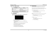
..." to the "IDE Function Setup" label and then press the enter key, it will take you a submenu with the following options: OnChip IDE Channel 0/1 The motherboard chipset contains a PCI IDE interface with support for two IDE channels. The Choices: Enabled (default), Disabled. 15 Integrated Peripherals IDE Function Setup If you are... IDE interface. Select "Disabled" to deactivate an interface if you highlight the literal "Press Enter" next to activate the first and/or second IDE interface. TForce4 SLI 5 Integrated Peripherals Figure 5.
..." to the "IDE Function Setup" label and then press the enter key, it will take you a submenu with the following options: OnChip IDE Channel 0/1 The motherboard chipset contains a PCI IDE interface with support for two IDE channels. The Choices: Enabled (default), Disabled. 15 Integrated Peripherals IDE Function Setup If you are... IDE interface. Select "Disabled" to deactivate an interface if you highlight the literal "Press Enter" next to activate the first and/or second IDE interface. TForce4 SLI 5 Integrated Peripherals Figure 5.

