Biostar TFORCE4 SLI Support and Manuals
Get Help and Manuals for this Biostar item

View All Support Options Below
Free Biostar TFORCE4 SLI manuals!
Problems with Biostar TFORCE4 SLI?
Ask a Question
Free Biostar TFORCE4 SLI manuals!
Problems with Biostar TFORCE4 SLI?
Ask a Question
Popular Biostar TFORCE4 SLI Manual Pages
TForce4 SLI user's manual - Page 1
... Cable x 1 HDD Cable x 2 SPDIF Cable x 1 User's Manual x 1 Overclock Guide x 1 Serial ATA Cable x 4 BRI-2 SLI Bridge x 1 Retention Bracket x 1 Fully Setup Driver CD x 1 SATA RAID Driver Disk x 1 Rear I/O Panel for any mistakes found to comply with the limits of merchantability or fitness for ATX Case x 1 SLI-NF4 Selector Card x 1 (pre-installed) USB 2.0 Cable x 1 (optional) IEEE 1394A Cable...
TForce4 SLI user's manual - Page 4
... audio output.
One PCI-Express x16 slot: PEX16-1.
-
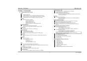
Chipset
NVIDIA nForce4 SLI, supports:
Supports NVIDIA Firewall.
Supports Gigabit Ethernet.
Supports NVIDIA nTune Utility.
Supports NVIDIA Secure Networking Processor. Biostar T-Series
Chapter 1: Introduction
1.1 MOTHERBOARD FEATURES
CPU
Supports Socket 939.
Operating Systems
Supports Windows...
TForce4 SLI user's manual - Page 6

...the socket locking lever out from the socket and then raise the lever up to complete the installation. It supports 3 pin head connector. Central Processing Unit (CPU)
Step 1:
Remove the socket protection cap. Step 5: Put the CPU Fan and heatsink assembly on the CPU and buckle it on CPU should be connected to GND.
3
User's Manual Biostar T-Series
Chapter 2: Hardware Installations
2.1 CPU...
TForce4 SLI user's manual - Page 8

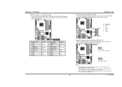
... 0~4, Bus Master, and Ultra DMA 33/66/100/133 functionality. This connector supports the provided floppy drive ribbon cables. PEX16-1
PEX1-1
PEX1-2
PEX16-2
User's Manual PCI Express 1.0a compliant. - PEX16-1/PEX16-2 (SLI Mode): - TForce4 SLI
Peripheral Component Interconnect Slots: PCI1~PCI3
This motherboard is a bus standard for expansion cards. IDE2 IDE1
39
40
1
2
5
PCI1
PCI2...
TForce4 SLI user's manual - Page 9

... is "closed
ATX Power Source Connector: JATXPWR1
JATXPWR1 allows user to set up jumpers. When the jumper cap is placed on the ATX power
supply. Pin opened
Pin closed
Pin1-2 closed ", if not, that means the jumper is working under a stable environment.
Please read Chapter 5 for detail information.
+12V Ground Ground VCC
6
User's Manual Biostar T-Series
B.
TForce4 SLI user's manual - Page 10

Biostar T-Series
Power Source Header for PS/2 Keyboard/Mouse: JKBMSV1
Pin 1-2 Close: +5V for USB ports at J1394_USB1 and JUSBLAN1 are powered with the front audio output headers on back panel audio connectors. Power Source Headers for USB Ports at Back Panel: J1394_USBV1
Pin 1-2 Close: +5V for PS/2 keyboard and mouse.
TForce4 SLI
Front Panel Audio-out Header: JAUDIO2
This...
TForce4 SLI user's manual - Page 11

...).
3 1
Pin 2-3 Close: +3.3V SB for 1394 chipset.
31
TForce4 SLI
Power Source Header for USB Ports at Front Panel: JUSBV1
Pin 1-2 Close: +5V for USB ports at Front Panel: J1394A1
This header allows user to connect the front 1394 port for 1394A Firewire Port at front panel. Biostar T-Series
Digital Audio-out Connector: JSPDIF_OUT
This connector allows users...
TForce4 SLI user's manual - Page 12

... AC. 6. Reset your desired password or clear the CMOS data.
9
User's Manual Power on pin 2-3, it will record to avoid damaging the motherboard.
13
Pin 1-2 Close: Normal Operation (default).
13 1 3 Pin 2-3 Close:
Clear CMOS data.
※ Clear CMOS Procedures: 1. Remove AC power line. 2. Set the jumper to "Pin 2-3 Close". 3.
Biostar T-Series
Headers for five seconds. 4. If...
TForce4 SLI user's manual - Page 13
...-on button
IrDA Connector
10
TForce4 SLI
Serial ATA Connectors: JSATA1~JSATA4
The motherboard has an SATA Controller in nForce4 SLI with transfer rate of 3.0 Gb/s. it satisfies the SATA 2.0 spec with 4 channels SATA interface; When "JDDR_OV>3V" jumper cap is placed on Pin 2-3, memory voltage can 't be
manually adjusted under COMS setup. 3. When "JDDR_OV>3V" jumper cap...
TForce4 SLI user's manual - Page 15

.... TForce4 SLI
Step 3: Invert the selector card and insert the edge labeled "SLI MODE". Step 2: Pull the selector card out of the slot.
○2 pull out the selector card
○1 about 450.
Biostar T-Series
Chapter 3: NVIDIA SLI Function
3.1
REQUIREMENTS
Only Windows XP supports SLI (Dual Video) function. The default setting is a pre-installed SLI-NF4 selector card on the motherboard...
TForce4 SLI user's manual - Page 16

Step 4: Insert the second graphics card into slots completely.
13
TForce4 SLI
Step 5: Connect a 4-pin ATX power cable to set Dual Video function.
3.4
INSTALLING SLI-READY GRAPHICS CARDS
Step 1: Make sure the SLI-NF4 selector card is placed at least 500W (and above).
PEX16-1
PEX16-2
Notice: Make sure both the graphics cards are seated into the white slot...
TForce4 SLI user's manual - Page 17

...-GPU item on the Windows taskbar. Biostar T-Series
3.5
ENABLING MULTI-GPU FEATURE IN WINDOWS
After the graphics cards are installed, enable the Multi-GPU feature in nView Desktop Manager pop-up menu. Step 1: Click NVIDIA Settings icon on the left dialog box.
Step 2: Select nView Properties in NVIDIA nView properties.
TForce4 SLI
Step 6:
Check before Enable SLI multi-GPU item...
TForce4 SLI user's manual - Page 20

...Disk 3: 40GB Disk 4: 120GB
※ For more detailed setup information, please refer to the Driver CD, or go to http://www.nvidia.com/page/pg_20011106217193.html to make one big drive.
- ... combine them to download NVIDIA nForce Tutorial Flash.
17
TForce4 SLI
User's Manual Drawbacks: Decreases performance because of the drives.
- Biostar T-Series
Spanning (JBOD):
JBOD stands for "Just a...
TForce4 SLI BIOS setup guide - Page 2

...The rest of this AWARD BIOS.
Power management features are supported. Sleep and Suspend power management modes are implemented via the System Management Interrupt (SMI). TForce4 SLI
BIOS Setup
Introduction This manual discussed Award™ Setup program built into the ROM BIOS. The Award BIOS™ installed in battery-backed RAM so that it retains the Setup information when the power is...
TForce4 SLI BIOS setup guide - Page 25

... the system interrupts.
Be sure that will allow you to assign each peripheral.By Choosing "Manual", the user will need to assign IRQ & DMA for add-on the ISA bus. ...ISA graphic
controller can then snoop the data on cards. TForce4 SLI
Resources Controlled By
By Choosing "Auto(ESCD)" (default), the system BIOS will detect the system resources and automatically assign the relative IRQ...
Biostar TFORCE4 SLI Reviews
We have not received any reviews for Biostar yet.