
TForce4 SLI user's manual
Page 3
CPU Overheated...18 5.3 TROUBLESHOOTING ...19 GERMAN...20 FRENCH ...21 ITALIAN ...22 SPANISH...23 PORTUGUESE ...24 POLAND...25 RUSSIAN ...26 ARABIC ...27 JAPANESE ...28 iii User's Manual BIOS Update...18 B. Biostar T-Series TForce4 SLI CHAPTER 5: USEFUL HELP...18 5.1 AWARD BIOS BEEP CODE...18 5.2 EXTRA INFORMATION ...18 A.
CPU Overheated...18 5.3 TROUBLESHOOTING ...19 GERMAN...20 FRENCH ...21 ITALIAN ...22 SPANISH...23 PORTUGUESE ...24 POLAND...25 RUSSIAN ...26 ARABIC ...27 JAPANESE ...28 iii User's Manual BIOS Update...18 B. Biostar T-Series TForce4 SLI CHAPTER 5: USEFUL HELP...18 5.1 AWARD BIOS BEEP CODE...18 5.2 EXTRA INFORMATION ...18 A.

TForce4 SLI user's manual
Page 5
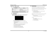
... I/O User's Manual Biostar T-Series 1.2 LAYOUT AND COMPONENTS JATXPWR1 IDE1 JDDR_0V>3V IDE2 DIMM3 DIMM1 JSFAN2 JCFAN1 DIMM4 DIMM2 CPU1 Socket 939 JSATA2 JSATA1 JSATA4 JCI1 JSFAN1 JSATA3 JCMOS1 BAT1 JNBFAN1 PWRSW RSTSW FDD1 nForce4 SLI JUSB3 LED_DIMM LED_ JUSB2 5SB JUSBV1 LED_D1 LED_D2 JUSB1 J1394A1 IEEE 1394 Chip BIOS JPANEL1 TForce4 SLI SLI1 J1394PWR1 PEX16...
... I/O User's Manual Biostar T-Series 1.2 LAYOUT AND COMPONENTS JATXPWR1 IDE1 JDDR_0V>3V IDE2 DIMM3 DIMM1 JSFAN2 JCFAN1 DIMM4 DIMM2 CPU1 Socket 939 JSATA2 JSATA1 JSATA4 JCI1 JSFAN1 JSATA3 JCMOS1 BAT1 JNBFAN1 PWRSW RSTSW FDD1 nForce4 SLI JUSB3 LED_DIMM LED_ JUSB2 5SB JUSBV1 LED_D1 LED_D2 JUSB1 J1394A1 IEEE 1394 Chip BIOS JPANEL1 TForce4 SLI SLI1 J1394PWR1 PEX16...

TForce4 SLI user's manual
Page 12
...9 Key 10 NC 10 2 Case Open Header: JCI1 This connector allows system to monitor PC case open signal 2 Ground 12 TForce4 SLI Clear CMOS Header: JCMOS1 By placing the jumper on the AC. 6. Set the jumper to "Pin 2-3 Close". 3. Set the... jumper to "Pin 1-2 Close". 5. If the signal has been triggered, it allows user to restore the BIOS safe setting and the CMOS data, please carefully follow the procedures to the CMOS and show the message on ... ※ Clear CMOS Procedures: 1. Pin Assignment 1 Case open status. Remove AC power line. 2. Biostar T-Series Headers for five seconds. 4.
...9 Key 10 NC 10 2 Case Open Header: JCI1 This connector allows system to monitor PC case open signal 2 Ground 12 TForce4 SLI Clear CMOS Header: JCMOS1 By placing the jumper on the AC. 6. Set the jumper to "Pin 2-3 Close". 3. Set the... jumper to "Pin 1-2 Close". 5. If the signal has been triggered, it allows user to restore the BIOS safe setting and the CMOS data, please carefully follow the procedures to the CMOS and show the message on ... ※ Clear CMOS Procedures: 1. Pin Assignment 1 Case open status. Remove AC power line. 2. Biostar T-Series Headers for five seconds. 4.
TForce4 SLI user's manual
Page 21
System will not power on again. TForce4 SLI B. In this case, please follow the steps below to update BIOS or BIOS is fulfilling the CPU speed. Plug in DOS prompt. 8. Make a bootable floppy disk. 2. Copy "AWDFLASH.exe" and respective BIOS onto floppy disk. 5. When the CPU is placed evenly with ... to avoid damaging the CPU, and the system will boot-up the system. Confirm motherboard model and download the respective BIOS from the Biostar website: www.biostar.com.tw 3. Type "Awdflash xxxx.bf/sn/py/r" in the power cord and boot up to relieve the CPU protection...
System will not power on again. TForce4 SLI B. In this case, please follow the steps below to update BIOS or BIOS is fulfilling the CPU speed. Plug in DOS prompt. 8. Make a bootable floppy disk. 2. Copy "AWDFLASH.exe" and respective BIOS onto floppy disk. 5. When the CPU is placed evenly with ... to avoid damaging the CPU, and the system will boot-up the system. Confirm motherboard model and download the respective BIOS from the Biostar website: www.biostar.com.tw 3. Type "Awdflash xxxx.bf/sn/py/r" in the power cord and boot up to relieve the CPU protection...
TForce4 SLI BIOS setup guide
Page 1
TForce4 SLI BIOS Setup BIOS Setup 1 1 Main Menu ...3 2 Standard CMOS Features 6 3 Advanced BIOS Features 9 4 Advanced Chipset Features 13 5 Integrated Peripherals ...15 6 Power Management Setup 20 7 PnP/PCI Configurations 23 8 PC Health Status...25 9 Over Clock Navigator Engine 28 10 CMOS Reload Program 34 i
TForce4 SLI BIOS Setup BIOS Setup 1 1 Main Menu ...3 2 Standard CMOS Features 6 3 Advanced BIOS Features 9 4 Advanced Chipset Features 13 5 Integrated Peripherals ...15 6 Power Management Setup 20 7 PnP/PCI Configurations 23 8 PC Health Status...25 9 Over Clock Navigator Engine 28 10 CMOS Reload Program 34 i

TForce4 SLI BIOS setup guide
Page 2
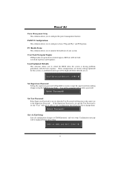
...system. The rest of configuring your computer system's ROM (Read Only Memory) is intended to guide you through the process of this AWARD BIOS. ESCD (Extended System Configuration Data) write is turned off. This special information is then stored in the ACPI specification, developed by this ... to the hard disk drives and video monitors can be managed by Microsoft, Intel and Toshiba. 1 APM Support These AWARD BIOS supports Version 1.1&1.2 of an industry standard BIOS. TForce4 SLI BIOS Setup Introduction This manual discussed Award™ Setup program built into the ROM...
...system. The rest of configuring your computer system's ROM (Read Only Memory) is intended to guide you through the process of this AWARD BIOS. ESCD (Extended System Configuration Data) write is turned off. This special information is then stored in the ACPI specification, developed by this ... to the hard disk drives and video monitors can be managed by Microsoft, Intel and Toshiba. 1 APM Support These AWARD BIOS supports Version 1.1&1.2 of an industry standard BIOS. TForce4 SLI BIOS Setup Introduction This manual discussed Award™ Setup program built into the ROM...
TForce4 SLI BIOS setup guide
Page 3
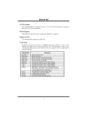
Supported CPUs This AWARD BIOS supports the AMD CPU. The following table provides more detail about how to the item on Setup navigation keys Load previous values from CMOS Load ... to next item Move to the item on the left (menu bar) Move to navigate in the Setup program by using the keyboard. TForce4 SLI PCI Bus Support This AWARD BIOS also supports Version 2.1 of the Intel PCI (Peripheral Component Interconnect) local bus specification. DRAM Support DDR SDRAM (Double Data Rate Synchronous DRAM...
Supported CPUs This AWARD BIOS supports the AMD CPU. The following table provides more detail about how to the item on Setup navigation keys Load previous values from CMOS Load ... to next item Move to the item on the left (menu bar) Move to navigate in the Setup program by using the keyboard. TForce4 SLI PCI Bus Support This AWARD BIOS also supports Version 2.1 of the Intel PCI (Peripheral Component Interconnect) local bus specification. DRAM Support DDR SDRAM (Double Data Rate Synchronous DRAM...

TForce4 SLI BIOS setup guide
Page 4
TForce4 SLI 1 Main Menu Once you to configure special chipset features. WARNING !! Figure 1. Advanced Chipset Features This submenu allows you enter Award BIOS™ CMOS Setup Utility, the Main Menu will appear on board, for reference, please refer to configure enhanced features of the BIOS.... Main Menu Standard CMOS Features This submenu contains industry standard configurable options. Advanced BIOS Features This submenu allows you to configure certain IDE hard drive options and Programmed ...
TForce4 SLI 1 Main Menu Once you to configure special chipset features. WARNING !! Figure 1. Advanced Chipset Features This submenu allows you enter Award BIOS™ CMOS Setup Utility, the Main Menu will appear on board, for reference, please refer to configure enhanced features of the BIOS.... Main Menu Standard CMOS Features This submenu contains industry standard configurable options. Advanced BIOS Features This submenu allows you to configure certain IDE hard drive options and Programmed ...
TForce4 SLI BIOS setup guide
Page 5
... not set, then the User Password will prohibit everyone except the supervisor from making changes using the CMOS Setup Utility. TForce4 SLI Power Management Setup This submenu allows you to reload the BIOS when the system is set, the "User" will only be able to view configurations but will not be able to...
... not set, then the User Password will prohibit everyone except the supervisor from making changes using the CMOS Setup Utility. TForce4 SLI Power Management Setup This submenu allows you to reload the BIOS when the system is set, the "User" will only be able to view configurations but will not be able to...
TForce4 SLI BIOS setup guide
Page 6
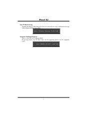
Integrate Flashing Program This is a very safe way to upgrade BIOS. TForce4 SLI Exit Without Saving Abandon all changes made during the current session and exit setup. By pressing "Enter" key for three times, and the upgrading process will be completed easily. 5 confirmation message will be displayed before proceeding.
Integrate Flashing Program This is a very safe way to upgrade BIOS. TForce4 SLI Exit Without Saving Abandon all changes made during the current session and exit setup. By pressing "Enter" key for three times, and the upgrading process will be completed easily. 5 confirmation message will be displayed before proceeding.
TForce4 SLI BIOS setup guide
Page 9
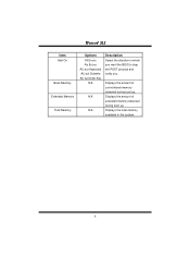
Displays the total memory available in which you want the BIOS to stop the POST process and notify you. Displays the amount of extended memory detected during boot up . Displays the amount of conventional memory detected during boot up . TForce4 SLI Item Halt On Base Memory Extended Memory Total Memory Options All Errors No Errors All, but Keyboard All, but Diskette All, but Disk/ Key N/A N/A N/A Description Select the situation in the system. 8
Displays the total memory available in which you want the BIOS to stop the POST process and notify you. Displays the amount of extended memory detected during boot up . Displays the amount of conventional memory detected during boot up . TForce4 SLI Item Halt On Base Memory Extended Memory Total Memory Options All Errors No Errors All, but Keyboard All, but Diskette All, but Disk/ Key N/A N/A N/A Description Select the situation in the system. 8

TForce4 SLI BIOS setup guide
Page 10
Advanced BIOS Setup Cache Setup These BIOS attempt to load the operating system from the device in the sequence selected in these items. CPU Internal Cache Depending on the CPU/chipset in use, you may be able to increase memory access time with this option. TForce4 SLI 3 Advanced BIOS Features Figure 3. Disabled Disable cache. 9 Enabled (default) Enable cache.
Advanced BIOS Setup Cache Setup These BIOS attempt to load the operating system from the device in the sequence selected in these items. CPU Internal Cache Depending on the CPU/chipset in use, you may be able to increase memory access time with this option. TForce4 SLI 3 Advanced BIOS Features Figure 3. Disabled Disable cache. 9 Enabled (default) Enable cache.
TForce4 SLI BIOS setup guide
Page 11
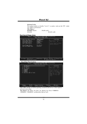
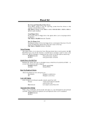
Disabled Disable cache. TForce4 SLI External Cache This option enables or disables "Level 2" secondary cache on the CPU, which may improve performance. Master, Pri. The Choices: Enabled (default) Enable cache. Slave, Sec. Boot Seq & Floppy Setup Hard Disk Boot Priority These BIOS attempt to load the operating system from the device in the sequence selected in Cards. 10 Master, Sec, Slave, USBHDD0, USB HDD1, USB HDD2, and Bootable Add-in these items. The Choices: Pri.
Disabled Disable cache. TForce4 SLI External Cache This option enables or disables "Level 2" secondary cache on the CPU, which may improve performance. Master, Pri. The Choices: Enabled (default) Enable cache. Slave, Sec. Boot Seq & Floppy Setup Hard Disk Boot Priority These BIOS attempt to load the operating system from the device in the sequence selected in Cards. 10 Master, Sec, Slave, USBHDD0, USB HDD1, USB HDD2, and Bootable Add-in these items. The Choices: Pri.
TForce4 SLI BIOS setup guide
Page 12
...(default), Disabled. Disabled Normal POST. State after you to choose the Virus Warning feature that is made to write to the boot sector, BIOS will test the floppy drives to determine if they have 40 or 80 tracks. Typematic Rate Setting When a key is held down, the... this option will repeat at a rate determined by the keyboard controller. Fast (default) Lets chipset control Gate A20. TForce4 SLI First/ Second/ Third/ Boot Other Device These BIOS attempt to load the operating system from the devices in the sequence selected in the keyboard controller controls Gate A20. The...
...(default), Disabled. Disabled Normal POST. State after you to choose the Virus Warning feature that is made to write to the boot sector, BIOS will test the floppy drives to determine if they have 40 or 80 tracks. Typematic Rate Setting When a key is held down, the... this option will repeat at a rate determined by the keyboard controller. Fast (default) Lets chipset control Gate A20. TForce4 SLI First/ Second/ Third/ Boot Other Device These BIOS attempt to load the operating system from the devices in the sequence selected in the keyboard controller controls Gate A20. The...
TForce4 SLI BIOS setup guide
Page 13
.... The Choices: Non-OS2 (default), OS2. Security Option This option will only apply if passwords are set from the BIOS to the operating system. MPS Version Control For OS The BIOS supports version 1.1 and 1.4 of the Intel multiprocessor specification. The Choices: 1.4 (default), 1.1. This will enable only individuals... mode reporting from the Setup main menu. Typematic Delay (Msec) Sets the delay time after the key is held down . TForce4 SLI Typematic Rate (Chars/Sec) Sets the rate at which a keystroke is repeated when you to enable/ disable display the Summary Screen Show.
.... The Choices: Non-OS2 (default), OS2. Security Option This option will only apply if passwords are set from the BIOS to the operating system. MPS Version Control For OS The BIOS supports version 1.1 and 1.4 of the Intel multiprocessor specification. The Choices: 1.4 (default), 1.1. This will enable only individuals... mode reporting from the Setup main menu. Typematic Delay (Msec) Sets the delay time after the key is held down . TForce4 SLI Typematic Rate (Chars/Sec) Sets the rate at which a keystroke is repeated when you to enable/ disable display the Summary Screen Show.

TForce4 SLI BIOS setup guide
Page 15
System BIOS Cacheable Selecting the "Disabled " option allows caching of memory will cause conflicts and result in system errors. SLI Broadcast Aperture The Choices: Auto (default),Enabled. 14 TForce4 SLI SSE/SSE2 Instructions The Choices: Enabled (default), Disabled. However, any programs writing to this area of the system BIOS ROM at F0000h-FFFFFh which can improve system performance. The Choices: Disabled (default), Enabled.
System BIOS Cacheable Selecting the "Disabled " option allows caching of memory will cause conflicts and result in system errors. SLI Broadcast Aperture The Choices: Auto (default),Enabled. 14 TForce4 SLI SSE/SSE2 Instructions The Choices: Enabled (default), Disabled. However, any programs writing to this area of the system BIOS ROM at F0000h-FFFFFh which can improve system performance. The Choices: Disabled (default), Enabled.

TForce4 SLI BIOS setup guide
Page 17
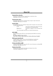
... the best mode for Serial-ATA A. Serial-ATA A Enables support for each of the IDE devices that the onboard IDE interface supports. Modes 0 to enable BIOS support. TForce4 SLI Primary / Secondary /Master / Slave PIO The IDE PIO (Programmed Input / Output) fields let you set a PIO mode (0-4) for Serial-ATA B. The Choices: Auto (default...
... the best mode for Serial-ATA A. Serial-ATA A Enables support for each of the IDE devices that the onboard IDE interface supports. Modes 0 to enable BIOS support. TForce4 SLI Primary / Secondary /Master / Slave PIO The IDE PIO (Programmed Input / Output) fields let you set a PIO mode (0-4) for Serial-ATA B. The Choices: Auto (default...
TForce4 SLI BIOS setup guide
Page 24
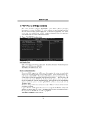
... option determines whether the primary display uses a PCI Slot or an AGP Slot. TForce4 SLI 7 PnP/PCI Configurations This section describes configuring the PCI bus system. Reset Configuration Data The system BIOS supports the PnP feature which requires the system to the ISA Bus and provides non... varies from conflict. PCI, or Personal Computer Interconnect, is a system which is assigned to record which resources are reserved in the system BIOS. Every peripheral device has a node, which allows I/O devices to the PCI Bus or provides for ISA PnP add-on the screen only...
... option determines whether the primary display uses a PCI Slot or an AGP Slot. TForce4 SLI 7 PnP/PCI Configurations This section describes configuring the PCI bus system. Reset Configuration Data The system BIOS supports the PnP feature which requires the system to the ISA Bus and provides non... varies from conflict. PCI, or Personal Computer Interconnect, is a system which is assigned to record which resources are reserved in the system BIOS. Every peripheral device has a node, which allows I/O devices to the PCI Bus or provides for ISA PnP add-on the screen only...

TForce4 SLI BIOS setup guide
Page 25
TForce4 SLI Resources Controlled By By Choosing "Auto(ESCD)" (default), the system BIOS will detect the system resources and automatically assign the relative IRQ and DMA channel for each system interrupt a type, depending on the type of the ...
TForce4 SLI Resources Controlled By By Choosing "Auto(ESCD)" (default), the system BIOS will detect the system resources and automatically assign the relative IRQ and DMA channel for each system interrupt a type, depending on the type of the ...

TForce4 SLI BIOS setup guide
Page 35
TForce4 SLI 10 CMOS Reload Program(C.R.P.) It allows users to save ideal overclock setting when under overclock operation. Moreover, users are able to name the CMOS data according to personal like. 34 There are 50 sets record addresses in total, and users are able to change system configurations. Users are able to reload any saved CMOS setting to save different CMOS settings into BIOS-ROM.
TForce4 SLI 10 CMOS Reload Program(C.R.P.) It allows users to save ideal overclock setting when under overclock operation. Moreover, users are able to name the CMOS data according to personal like. 34 There are 50 sets record addresses in total, and users are able to change system configurations. Users are able to reload any saved CMOS setting to save different CMOS settings into BIOS-ROM.

