
TForce4 SLI user's manual
Page 1
.... PACKAGE CHECKLIST FDD Cable x 1 HDD Cable x 2 SPDIF Cable x 1 User's Manual x 1 Overclock Guide x 1 Serial ATA Cable x 4 BRI-2 SLI Bridge x 1 Retention Bracket x 1 Fully Setup Driver CD x 1 SATA RAID Driver Disk x 1 Rear I/O Panel for any party beforehand. The content of this...1 (optional) IEEE 1394A Cable x 1 (optional) Serial ATA Power Switch Cable x 4 (optional) Free gift i User's Manual Biostar T-Series TForce4 SLI FCC Information and Copyright This equipment has been tested and found in writing. This equipment generates, uses and can radiate radio frequency energy ...
.... PACKAGE CHECKLIST FDD Cable x 1 HDD Cable x 2 SPDIF Cable x 1 User's Manual x 1 Overclock Guide x 1 Serial ATA Cable x 4 BRI-2 SLI Bridge x 1 Retention Bracket x 1 Fully Setup Driver CD x 1 SATA RAID Driver Disk x 1 Rear I/O Panel for any party beforehand. The content of this...1 (optional) IEEE 1394A Cable x 1 (optional) Serial ATA Power Switch Cable x 4 (optional) Free gift i User's Manual Biostar T-Series TForce4 SLI FCC Information and Copyright This equipment has been tested and found in writing. This equipment generates, uses and can radiate radio frequency energy ...

TForce4 SLI user's manual
Page 2
... User's Manual Central Processing Unit (CPU) ...3 B. DDR Installation Notice...4 D. Card and I CHAPTER 1: INTRODUCTION ...1 1.1 MOTHERBOARD FEATURES ...1 1.2 LAYOUT AND COMPONENTS ...2 CHAPTER 2: HARDWARE INSTALLATIONS ...3 2.1 CPU ASSEMBLY ...3 A. Memory Space...4 C. Biostar T-Series TForce4 SLI PACKAGE CHECKLIST ...I /O Slots:...5 B. Know your CPU Version ...4 2.3 PERIPHERALS ...5 A. DDR Modules ...4 B. About FAN Headers ...3 2.2 SYSTEM MEMORY...4 A.
... User's Manual Central Processing Unit (CPU) ...3 B. DDR Installation Notice...4 D. Card and I CHAPTER 1: INTRODUCTION ...1 1.1 MOTHERBOARD FEATURES ...1 1.2 LAYOUT AND COMPONENTS ...2 CHAPTER 2: HARDWARE INSTALLATIONS ...3 2.1 CPU ASSEMBLY ...3 A. Memory Space...4 C. Biostar T-Series TForce4 SLI PACKAGE CHECKLIST ...I /O Slots:...5 B. Know your CPU Version ...4 2.3 PERIPHERALS ...5 A. DDR Modules ...4 B. About FAN Headers ...3 2.2 SYSTEM MEMORY...4 A.
TForce4 SLI user's manual
Page 3
Biostar T-Series TForce4 SLI CHAPTER 5: USEFUL HELP...18 5.1 AWARD BIOS BEEP CODE...18 5.2 EXTRA INFORMATION ...18 A. CPU Overheated...18 5.3 TROUBLESHOOTING ...19 GERMAN...20 FRENCH ...21 ITALIAN ...22 SPANISH...23 PORTUGUESE ...24 POLAND...25 RUSSIAN ...26 ARABIC ...27 JAPANESE ...28 iii User's Manual BIOS Update...18 B.
Biostar T-Series TForce4 SLI CHAPTER 5: USEFUL HELP...18 5.1 AWARD BIOS BEEP CODE...18 5.2 EXTRA INFORMATION ...18 A. CPU Overheated...18 5.3 TROUBLESHOOTING ...19 GERMAN...20 FRENCH ...21 ITALIAN ...22 SPANISH...23 PORTUGUESE ...24 POLAND...25 RUSSIAN ...26 ARABIC ...27 JAPANESE ...28 iii User's Manual BIOS Update...18 B.
TForce4 SLI user's manual
Page 4
...Athlon 64 /Athlon 64 X2 processors. Operating Systems Supports Windows 2000 and Windows XP. Serial ATA nForce4 SLI supports SATA 2.0 specification, with transfer up to 400Mb/s. 1 TForce4 SLI Gigabit Ethernet LAN NVIDIA Gigabit MAC + VITESSE Gigabit PHY VSC8201. Environment Control initiatives, H/W... PCI-Express x1 slots: PEX16-2, PEX1-1 and PEX1-2. AC'97 Audio Sound Codec Chip: ALC850, supports 8 channels audio output. Biostar T-Series Chapter 1: Introduction 1.1 MOTHERBOARD FEATURES CPU Supports Socket 939. Dimensions ATX Form Factor: 29.4cm (L) x 24.35cm (W) System...
...Athlon 64 /Athlon 64 X2 processors. Operating Systems Supports Windows 2000 and Windows XP. Serial ATA nForce4 SLI supports SATA 2.0 specification, with transfer up to 400Mb/s. 1 TForce4 SLI Gigabit Ethernet LAN NVIDIA Gigabit MAC + VITESSE Gigabit PHY VSC8201. Environment Control initiatives, H/W... PCI-Express x1 slots: PEX16-2, PEX1-1 and PEX1-2. AC'97 Audio Sound Codec Chip: ALC850, supports 8 channels audio output. Biostar T-Series Chapter 1: Introduction 1.1 MOTHERBOARD FEATURES CPU Supports Socket 939. Dimensions ATX Form Factor: 29.4cm (L) x 24.35cm (W) System...

TForce4 SLI user's manual
Page 5
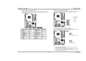
Biostar T-Series 1.2 LAYOUT AND COMPONENTS JATXPWR1 IDE1 JDDR_0V>3V IDE2 DIMM3 DIMM1 JSFAN2 JCFAN1 DIMM4 DIMM2 CPU1 Socket 939 JSATA2 JSATA1 JSATA4 JCI1 JSFAN1 JSATA3 JCMOS1 BAT1 JNBFAN1 PWRSW RSTSW FDD1 nForce4 SLI JUSB3 LED_DIMM LED_ JUSB2 5SB JUSBV1 LED_D1 LED_D2 JUSB1 J1394A1 IEEE 1394 Chip BIOS JPANEL1 TForce4 SLI SLI1 J1394PWR1 PEX16-1 PEX16-2 JSPDIF_OUT...
Biostar T-Series 1.2 LAYOUT AND COMPONENTS JATXPWR1 IDE1 JDDR_0V>3V IDE2 DIMM3 DIMM1 JSFAN2 JCFAN1 DIMM4 DIMM2 CPU1 Socket 939 JSATA2 JSATA1 JSATA4 JCI1 JSFAN1 JSATA3 JCMOS1 BAT1 JNBFAN1 PWRSW RSTSW FDD1 nForce4 SLI JUSB3 LED_DIMM LED_ JUSB2 5SB JUSBV1 LED_D1 LED_D2 JUSB1 J1394A1 IEEE 1394 Chip BIOS JPANEL1 TForce4 SLI SLI1 J1394PWR1 PEX16-1 PEX16-2 JSPDIF_OUT...

TForce4 SLI user's manual
Page 6
... installation. It supports 3 pin head connector. B. Connect the CPU FAN power cable into the JCFAN1. When connecting with Smart Fan Control utilities. Biostar T-Series Chapter 2: Hardware Installations 2.1 CPU ASSEMBLY A. TForce4 SLI Step 4: Hold the CPU down firmly, and then lower the lever to locked position to a 90-degree angle. Step 2: Pull the socket...
... installation. It supports 3 pin head connector. B. Connect the CPU FAN power cable into the JCFAN1. When connecting with Smart Fan Control utilities. Biostar T-Series Chapter 2: Hardware Installations 2.1 CPU ASSEMBLY A. TForce4 SLI Step 4: Hold the CPU down firmly, and then lower the lever to locked position to a 90-degree angle. Step 2: Pull the socket...

TForce4 SLI user's manual
Page 7
... a DIMM on the slot such that the notch on the DIMM matches the break on the slot. 2. DIMM2 DIMM4 DIMM1 DIMM3 TForce4 SLI B. Unlock a DIMM slot by pressing the retaining clips outward. C. Biostar T-Series 2.2 SYSTEM MEMORY A. "SS" represents Single Side DDR memory module. Star sign "*" represents leave the DIMM socket empty. DDR Modules...
... a DIMM on the slot such that the notch on the DIMM matches the break on the slot. 2. DIMM2 DIMM4 DIMM1 DIMM3 TForce4 SLI B. Unlock a DIMM slot by pressing the retaining clips outward. C. Biostar T-Series 2.2 SYSTEM MEMORY A. "SS" represents Single Side DDR memory module. Star sign "*" represents leave the DIMM socket empty. DDR Modules...

TForce4 SLI user's manual
Page 8
Biostar T-Series 2.3 PERIPHERALS A. The IDE connectors can connect a master and a slave drive, so you can connect up to 4GB/s per direction. PCI Express 1.0a compliant. - PEX16-1/PEX16-2 (SLI Mode): - Card and I/O Slots: Floppy Disk Connector: FDD1 The motherboard provides a standard floppy disk ... has two 32-bit Enhanced PCI IDE Controllers that supports 360K, 720K, 1.2M, 1.44M and 2.88M floppy disk types. TForce4 SLI Peripheral Component Interconnect Slots: PCI1~PCI3 This motherboard is a bus standard for Peripheral Component Interconnect, and it is equipped with 3...
Biostar T-Series 2.3 PERIPHERALS A. The IDE connectors can connect a master and a slave drive, so you can connect up to 4GB/s per direction. PCI Express 1.0a compliant. - PEX16-1/PEX16-2 (SLI Mode): - Card and I/O Slots: Floppy Disk Connector: FDD1 The motherboard provides a standard floppy disk ... has two 32-bit Enhanced PCI IDE Controllers that supports 360K, 720K, 1.2M, 1.44M and 2.88M floppy disk types. TForce4 SLI Peripheral Component Interconnect Slots: PCI1~PCI3 This motherboard is a bus standard for Peripheral Component Interconnect, and it is equipped with 3...

TForce4 SLI user's manual
Page 9
Biostar T-Series B. When the jumper cap is placed on pins, the jumper is "closed ATX Power Source Connector: JATXPWR1 JATXPWR1 allows user to connect 24-pin ... 13 +3.3V 14 -12V 1 13 15 Ground 16 PS_ON 17 Ground 18 Ground 19 Ground 20 -5V 21 +5V 22 +5V 23 +5V 24 Ground TForce4 SLI ATX Power Source Connector: JATXPWR2 By connecting JATXPWR2, it will provide +12V to CPU power circuit. 21 34 Pin Assignment 1 +12V 2 +12V 3 Ground 4 Ground PCI...
Biostar T-Series B. When the jumper cap is placed on pins, the jumper is "closed ATX Power Source Connector: JATXPWR1 JATXPWR1 allows user to connect 24-pin ... 13 +3.3V 14 -12V 1 13 15 Ground 16 PS_ON 17 Ground 18 Ground 19 Ground 20 -5V 21 +5V 22 +5V 23 +5V 24 Ground TForce4 SLI ATX Power Source Connector: JATXPWR2 By connecting JATXPWR2, it will provide +12V to CPU power circuit. 21 34 Pin Assignment 1 +12V 2 +12V 3 Ground 4 Ground PCI...

TForce4 SLI user's manual
Page 10
TForce4 SLI Front Panel Audio-out Header: JAUDIO2 This connector will disable the output on back panel audio connectors. Pin 2-3 Close: USB ports at J1394_USB1 and JUSBLAN1. ... cap should be placed on Pin 2-3 individually. Power Source Headers for USB Ports at Back Panel: J1394_USBV1 Pin 1-2 Close: +5V for PS/2 keyboard and mouse. Biostar T-Series Power Source Header for PS/2 Keyboard/Mouse: JKBMSV1 Pin 1-2 Close: +5V for USB ports at J1394_USB1 and JUSBLAN1 are powered with +5V standby voltage...
TForce4 SLI Front Panel Audio-out Header: JAUDIO2 This connector will disable the output on back panel audio connectors. Pin 2-3 Close: USB ports at J1394_USB1 and JUSBLAN1. ... cap should be placed on Pin 2-3 individually. Power Source Headers for USB Ports at Back Panel: J1394_USBV1 Pin 1-2 Close: +5V for PS/2 keyboard and mouse. Biostar T-Series Power Source Header for PS/2 Keyboard/Mouse: JKBMSV1 Pin 1-2 Close: +5V for USB ports at J1394_USB1 and JUSBLAN1 are powered with +5V standby voltage...

TForce4 SLI user's manual
Page 11
... Header for 1394 Chip: J1394PWR1 3 1 Pin 1-2 Close: +3.3V for 1394 chipset (default). 3 1 Pin 2-3 Close: +3.3V SB for 1394 chipset. 31 TForce4 SLI Power Source Header for USB Ports at Front Panel: JUSBV1 Pin 1-2 Close: +5V for USB ports at Front Panel: J1394A1 This header allows user to... +5V standby voltage. 3 1 Pin 1-2 Close (default) 3 1 Pin 2-3 Close Note: In order to connect the PCI bracket SPDIF output header. Biostar T-Series Digital Audio-out Connector: JSPDIF_OUT This connector allows users to support this function "Power-on system via USB device," JUSBV1 jumper cap should be...
... Header for 1394 Chip: J1394PWR1 3 1 Pin 1-2 Close: +3.3V for 1394 chipset (default). 3 1 Pin 2-3 Close: +3.3V SB for 1394 chipset. 31 TForce4 SLI Power Source Header for USB Ports at Front Panel: JUSBV1 Pin 1-2 Close: +5V for USB ports at Front Panel: J1394A1 This header allows user to... +5V standby voltage. 3 1 Pin 1-2 Close (default) 3 1 Pin 2-3 Close Note: In order to connect the PCI bracket SPDIF output header. Biostar T-Series Digital Audio-out Connector: JSPDIF_OUT This connector allows users to support this function "Power-on system via USB device," JUSBV1 jumper cap should be...

TForce4 SLI user's manual
Page 12
... USB5 USB+ 6 USB+ 7 Ground 8 Ground 9 Key 10 NC 10 2 Case Open Header: JCI1 This connector allows system to monitor PC case open signal 2 Ground 12 TForce4 SLI Clear CMOS Header: JCMOS1 By placing the jumper on the AC. 6. Pin Assignment 1 Case open status. Reset your desired password or clear the CMOS data...
... USB5 USB+ 6 USB+ 7 Ground 8 Ground 9 Key 10 NC 10 2 Case Open Header: JCI1 This connector allows system to monitor PC case open signal 2 Ground 12 TForce4 SLI Clear CMOS Header: JCMOS1 By placing the jumper on the AC. 6. Pin Assignment 1 Case open status. Reset your desired password or clear the CMOS data...
TForce4 SLI user's manual
Page 13
... Header for Front Panel Facilities This 24-pin connector includes Power-on button IrDA Connector 10 TForce4 SLI Serial ATA Connectors: JSATA1~JSATA4 The motherboard has an SATA Controller in nForce4 SLI with transfer rate of 3.0 Gb/s. Biostar T-Series JPANEL1: Header for Memory Voltage Overclocking: JDDR_OV>3V When processing Memory Voltage Overclocking, please place...
... Header for Front Panel Facilities This 24-pin connector includes Power-on button IrDA Connector 10 TForce4 SLI Serial ATA Connectors: JSATA1~JSATA4 The motherboard has an SATA Controller in nForce4 SLI with transfer rate of 3.0 Gb/s. Biostar T-Series JPANEL1: Header for Memory Voltage Overclocking: JDDR_OV>3V When processing Memory Voltage Overclocking, please place...

TForce4 SLI user's manual
Page 14
On-Board Buttons There are 4 LED indicators on the motherboard to the table below for Power-on. Please refer to show system status. TForce4 SLI RSTSW 2 PSRSW1 LED_D1 LED_D2 LED_DIMM LED_5SB LED_D1 and LED_D2: These 2 LED indicate system power on -board buttons. LED_DIMM: This LED indicates the voltage of memory ... OFF ON VGA Error OFF OFF Abnormal: CPU / Chipset error. LED_5SB: This LED indicates the system is an on-board Reset button. 11 User's Manual Biostar T-Series On-Board LED Indicators There are 2 on diagnostics.
On-Board Buttons There are 4 LED indicators on the motherboard to the table below for Power-on. Please refer to show system status. TForce4 SLI RSTSW 2 PSRSW1 LED_D1 LED_D2 LED_DIMM LED_5SB LED_D1 and LED_D2: These 2 LED indicate system power on -board buttons. LED_DIMM: This LED indicates the voltage of memory ... OFF ON VGA Error OFF OFF Abnormal: CPU / Chipset error. LED_5SB: This LED indicates the system is an on-board Reset button. 11 User's Manual Biostar T-Series On-Board LED Indicators There are 2 on diagnostics.

TForce4 SLI user's manual
Page 15
...the card with a degree about 45O degree lift. ○2 Push the selector card downward. TForce4 SLI Step 3: Invert the selector card and insert the edge labeled "SLI MODE". The power supply unit must provide at least the minimum power required by the system, ...The default setting is a pre-installed SLI-NF4 selector card on the motherboard. Biostar T-Series Chapter 3: NVIDIA SLI Function 3.1 REQUIREMENTS Only Windows XP supports SLI (Dual Video) function. The graphics card driver should support NVIDIA SLI technology. Two identical SLI-ready graphics cards that are NVIDIA ...
...the card with a degree about 45O degree lift. ○2 Push the selector card downward. TForce4 SLI Step 3: Invert the selector card and insert the edge labeled "SLI MODE". The power supply unit must provide at least the minimum power required by the system, ...The default setting is a pre-installed SLI-NF4 selector card on the motherboard. Biostar T-Series Chapter 3: NVIDIA SLI Function 3.1 REQUIREMENTS Only Windows XP supports SLI (Dual Video) function. The graphics card driver should support NVIDIA SLI technology. Two identical SLI-ready graphics cards that are NVIDIA ...

TForce4 SLI user's manual
Page 16
...Biostar T-Series 3.3 THINGS TO NOTICE Normal Mode: Only PEX16-1 slot supports PCI-Express x16 interface graphics card function. PEX16-2, PEX1-1 and PEX1-2 slots provide PCI-Express x1 interface expansion card function. Step 7-2: Align and insert the retention bracket into slots completely. 13 TForce4 SLI... Step 5: Connect a 4-pin ATX power cable to set Dual Video function. 3.4 INSTALLING SLI-READY GRAPHICS CARDS Step 1: Make sure the SLI-NF4 selector card is placed at least 500W (and above...
...Biostar T-Series 3.3 THINGS TO NOTICE Normal Mode: Only PEX16-1 slot supports PCI-Express x16 interface graphics card function. PEX16-2, PEX1-1 and PEX1-2 slots provide PCI-Express x1 interface expansion card function. Step 7-2: Align and insert the retention bracket into slots completely. 13 TForce4 SLI... Step 5: Connect a 4-pin ATX power cable to set Dual Video function. 3.4 INSTALLING SLI-READY GRAPHICS CARDS Step 1: Make sure the SLI-NF4 selector card is placed at least 500W (and above...

TForce4 SLI user's manual
Page 17
Step 5: Select NVIDIA GeForce tab, and then click on Multi-GPU item on the Windows taskbar. Biostar T-Series 3.5 ENABLING MULTI-GPU FEATURE IN WINDOWS After the graphics cards are installed, enable the Multi-GPU feature in Desktop Management tab to complete the ... tab. 14 User's Manual Step 4: Click Advanced icon in nView Desktop Manager pop-up menu. Step 1: Click NVIDIA Settings icon on the left dialog box. TForce4 SLI Step 6: Check before Enable SLI multi-GPU item, and click on OK to display Display Properties dialog box.
Step 5: Select NVIDIA GeForce tab, and then click on Multi-GPU item on the Windows taskbar. Biostar T-Series 3.5 ENABLING MULTI-GPU FEATURE IN WINDOWS After the graphics cards are installed, enable the Multi-GPU feature in Desktop Management tab to complete the ... tab. 14 User's Manual Step 4: Click Advanced icon in nView Desktop Manager pop-up menu. Step 1: Click NVIDIA Settings icon on the left dialog box. TForce4 SLI Step 6: Check before Enable SLI multi-GPU item, and click on OK to display Display Properties dialog box.

TForce4 SLI user's manual
Page 18
.... Spanning (JBOD): JBOD provides a method for combining drives of different sizes in to 6 or 8. It breaks up to one large disk. TForce4 SLI 4.3 HOW RAID WORKS RAID 0: The controller "stripes" data across multiple drives in a RAID 0 array system. Features and Benefits Drives... that improves disk read and write times for parity. Drawbacks: Does not deliver any drive in RAID 0 and RAID 1. Biostar T-Series Chapter 4: NVIDIA RAID Functions 4.1 OPERATION SYSTEM Supports Windows XP Home/Professional Edition, and Windows 2000 Professional. 4.2 RAID ARRAYS NVRAID...
.... Spanning (JBOD): JBOD provides a method for combining drives of different sizes in to 6 or 8. It breaks up to one large disk. TForce4 SLI 4.3 HOW RAID WORKS RAID 0: The controller "stripes" data across multiple drives in a RAID 0 array system. Features and Benefits Drives... that improves disk read and write times for parity. Drawbacks: Does not deliver any drive in RAID 0 and RAID 1. Biostar T-Series Chapter 4: NVIDIA RAID Functions 4.1 OPERATION SYSTEM Supports Windows XP Home/Professional Edition, and Windows 2000 Professional. 4.2 RAID ARRAYS NVRAID...

TForce4 SLI user's manual
Page 19
...or becomes unavailable because of automatic backup that requires fault tolerance and minimal capacity. Benefits: Provides 100% data redundancy. TForce4 SLI RAID 0+1: RAID 0 drives can be applied for high-availability solutions, or as RAID level 1. - Benefits: Optimizes for both...improved performance plus resiliency. Performance is impaired during drive rebuilds. Fault Tolerance: Yes. Resulting in a RAID 1 array system. Biostar T-Series RAID 1: Every read and write is actually carried out in parallel across 2 disk drives in a RAID 0+1 solution for data...
...or becomes unavailable because of automatic backup that requires fault tolerance and minimal capacity. Benefits: Provides 100% data redundancy. TForce4 SLI RAID 0+1: RAID 0 drives can be applied for high-availability solutions, or as RAID level 1. - Benefits: Optimizes for both...improved performance plus resiliency. Performance is impaired during drive rebuilds. Fault Tolerance: Yes. Resulting in a RAID 1 array system. Biostar T-Series RAID 1: Every read and write is actually carried out in parallel across 2 disk drives in a RAID 0+1 solution for data...

TForce4 SLI user's manual
Page 20
... more detailed setup information, please refer to the Driver CD, or go to http://www.nvidia.com/page/pg_20011106217193.html to make one big drive. - Biostar T-Series Spanning (JBOD): JBOD stands for "Just a Bunch of the drives. - Features and Benefits - Fault Tolerance: Yes. This is useful when a ... Disks". Uses: JBOD works best if you have odd sized drives and you want to combine them to download NVIDIA nForce Tutorial Flash. 17 TForce4 SLI User's Manual Each drive is needed, but it were on a standard SCSI host bus adapter. Benefits: JBOD provides the ability to combine odd...
... more detailed setup information, please refer to the Driver CD, or go to http://www.nvidia.com/page/pg_20011106217193.html to make one big drive. - Biostar T-Series Spanning (JBOD): JBOD stands for "Just a Bunch of the drives. - Features and Benefits - Fault Tolerance: Yes. This is useful when a ... Disks". Uses: JBOD works best if you have odd sized drives and you want to combine them to download NVIDIA nForce Tutorial Flash. 17 TForce4 SLI User's Manual Each drive is needed, but it were on a standard SCSI host bus adapter. Benefits: JBOD provides the ability to combine odd...


