
Setup Manual
Page 4
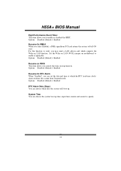
... Clear CMOS Header x1 Restore CMOS data to 3.0 Gb/s. Fan Speed Controller Low Pin Count Interface ITE's "Smart Guardian" function Main Memory DDR3 DIMM Slots x 4 Max Memory Capacity 16GB Each DIMM supports 512MB/ 1GB/2GB/4GB DDR3 Dual Channel Mode DDR3 memory module Supports DDR3 1600(OC)/1333/1066/800 Registered DIMM and ECC DIMM is not supported SATA 2 Integrated Serial ATA Controller Data transfer rates up to factory default USB Connector x3 Each connector supports 2 front panel USB ports 2 Motherboard Manual 1.3 MOTHERBOARD FEATURES SPEC Supports Execute Disable Bit...
... Clear CMOS Header x1 Restore CMOS data to 3.0 Gb/s. Fan Speed Controller Low Pin Count Interface ITE's "Smart Guardian" function Main Memory DDR3 DIMM Slots x 4 Max Memory Capacity 16GB Each DIMM supports 512MB/ 1GB/2GB/4GB DDR3 Dual Channel Mode DDR3 memory module Supports DDR3 1600(OC)/1333/1066/800 Registered DIMM and ECC DIMM is not supported SATA 2 Integrated Serial ATA Controller Data transfer rates up to factory default USB Connector x3 Each connector supports 2 front panel USB ports 2 Motherboard Manual 1.3 MOTHERBOARD FEATURES SPEC Supports Execute Disable Bit...
Setup Manual
Page 5
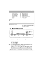
... motherboard supports Multiple VGA output, and the configuration is as below: (HDMI is not supported under DOS and BIOS setup.) Display Devices Enabled VGA + HDMI VGA + DVI-D HDMI + DVI-D O O X Caution: HDMI / DVI-D can not be plugged at the same time, or there will be no video output. 3 Consumer IR Connector Power Connector (24pin) Power Connector (4pin) PS/2 Keyboard / Mouse HDMI Port Back Panel I/O VGA Port DVI-D Port LAN Port USB Port Audio Jack Board Size 225(W) x 295 (L) mm OS Support Windows XP / Vista / 7 H55A+ SPEC x1 Supports infrared function x1 Connects to Power...
... motherboard supports Multiple VGA output, and the configuration is as below: (HDMI is not supported under DOS and BIOS setup.) Display Devices Enabled VGA + HDMI VGA + DVI-D HDMI + DVI-D O O X Caution: HDMI / DVI-D can not be plugged at the same time, or there will be no video output. 3 Consumer IR Connector Power Connector (24pin) Power Connector (4pin) PS/2 Keyboard / Mouse HDMI Port Back Panel I/O VGA Port DVI-D Port LAN Port USB Port Audio Jack Board Size 225(W) x 295 (L) mm OS Support Windows XP / Vista / 7 H55A+ SPEC x1 Supports infrared function x1 Connects to Power...

Setup Manual
Page 26
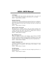
... the floppy disk that contains the BIOS file to enter the utility. 5. Select the device contains the BIOS file and press to the USB port or the floppy disk drive. 4. z Shutting down or resetting the system while updating the BIOS will show the BIOS files and their respective information. Power on the right appears. The BIO-Flasher is a BIOS flashing utility providing you to update your BIOS via USB pen drive or floppy disk. Go to the website to system boot failure...
... the floppy disk that contains the BIOS file to enter the utility. 5. Select the device contains the BIOS file and press to the USB port or the floppy disk drive. 4. z Shutting down or resetting the system while updating the BIOS will show the BIOS files and their respective information. Power on the right appears. The BIO-Flasher is a BIOS flashing utility providing you to update your BIOS via USB pen drive or floppy disk. Go to the website to system boot failure...

Setup Manual
Page 27
... are used for recovery 4 Flash Programming successful 5 File read error 7 No Flash EPROM detected 10 Flash Erase error 11 Flash Program error 12 "AMIBOOT.ROM" file size error 13 BIOS ROM image mismatch (file layout does not match image present in flash device) POST BIOS Beep Codes Number of Beeps Description 1 Memory refresh timer error 3 Base memory read/write test error 6 Keyboard controller BAT command failed 7 General exception error (processor exception interrupt error) 8 Display memory error (system video adapter) Troubleshooting POST BIOS Beep Codes Number...
... are used for recovery 4 Flash Programming successful 5 File read error 7 No Flash EPROM detected 10 Flash Erase error 11 Flash Program error 12 "AMIBOOT.ROM" file size error 13 BIOS ROM image mismatch (file layout does not match image present in flash device) POST BIOS Beep Codes Number of Beeps Description 1 Memory refresh timer error 3 Base memory read/write test error 6 Keyboard controller BAT command failed 7 General exception error (processor exception interrupt error) 8 Display memory error (system video adapter) Troubleshooting POST BIOS Beep Codes Number...

Bios Setup
Page 2
... in BIOS. ACPI Support AMI ACPI BIOS support Version 1.0/2.0 of the input and output devices such as keyboard, mouse, serial ports and disk drives. T he power of CMOS RAM is to describe the settings in BIOS Setup. EPA Green PC Support T his AMI BIOS supports the Plug and Play Version 1.0A specification. T he purpose of this manual is supplied by Microso ft, Intel and T oshiba. 1 Plug and Pla y Support T his AMI BIOS supports Version 1.03 of the EPA Green PC specification. T his system controls...
... in BIOS. ACPI Support AMI ACPI BIOS support Version 1.0/2.0 of the input and output devices such as keyboard, mouse, serial ports and disk drives. T he power of CMOS RAM is to describe the settings in BIOS Setup. EPA Green PC Support T his AMI BIOS supports the Plug and Play Version 1.0A specification. T he purpose of this manual is supplied by Microso ft, Intel and T oshiba. 1 Plug and Pla y Support T his AMI BIOS supports Version 1.03 of the EPA Green PC specification. T his system controls...

Bios Setup
Page 5
Main IDE/SATA Configuration Configure SATA as T his item allows you to control the onboard SAT A controller. Select a device and press to Sub Screen F1 General Help F10 Save and Exit ESC Exit vxx.xx (C)Copyright 1985-200x, American Megatrends, Inc. Options: Enhanced (Default) / Disabled 4 Configure SATA as SATA#1 Configuration SATA#2 Configuration > AHCI Configuration > SATA 1 Device > SATA 2 Device > SATA 3 Device > SATA 4 Device > SATA 5 Device > SATA 6 Device BIOS SETUP UTILITY [IDE] [Compatible] [Enhanced] Hard Disk Write Protect [Disabled] IDE/SATA Detect Time Out(Sec...
Main IDE/SATA Configuration Configure SATA as T his item allows you to control the onboard SAT A controller. Select a device and press to Sub Screen F1 General Help F10 Save and Exit ESC Exit vxx.xx (C)Copyright 1985-200x, American Megatrends, Inc. Options: Enhanced (Default) / Disabled 4 Configure SATA as SATA#1 Configuration SATA#2 Configuration > AHCI Configuration > SATA 1 Device > SATA 2 Device > SATA 3 Device > SATA 4 Device > SATA 5 Device > SATA 6 Device BIOS SETUP UTILITY [IDE] [Compatible] [Enhanced] Hard Disk Write Protect [Disabled] IDE/SATA Detect Time Out(Sec...

Bios Setup
Page 9
... > Smart Fan Configuration > ACPI Configuration > Onboard PCI/PCI-E Devices Configuration > Intel VT-d Configuration > MPS Configuration > PCI Express Configuration > Smbios Configuration > USB Configuration Configure CPU. Notice z Beware of that the BIOS automatically detects. Advanced BIOS S ETUP UTILITY Confi gure advanced CPU setting s Modul e Version:01. 04 Manuf acturer:Intel CPU Frequ ency : BCLK Speed : Cache L1 : Cache L2 : Cache L3 : Ratio Status: Ratio Actual Value : CIE S upport [Enabled] Hardw are Prefetche r [Enabled] Adjac ent Cache Lin e Prefetch [Enabled] Max...
... > Smart Fan Configuration > ACPI Configuration > Onboard PCI/PCI-E Devices Configuration > Intel VT-d Configuration > MPS Configuration > PCI Express Configuration > Smbios Configuration > USB Configuration Configure CPU. Notice z Beware of that the BIOS automatically detects. Advanced BIOS S ETUP UTILITY Confi gure advanced CPU setting s Modul e Version:01. 04 Manuf acturer:Intel CPU Frequ ency : BCLK Speed : Cache L1 : Cache L2 : Cache L3 : Ratio Status: Ratio Actual Value : CIE S upport [Enabled] Hardw are Prefetche r [Enabled] Adjac ent Cache Lin e Prefetch [Enabled] Max...
Bios Setup
Page 10
...latency associated with memory reads. Options: Disabled (Default) / Enabled 9 Befo re it can do so, it as well. H55A+ BIOS Manual C1E Support C1E is "Enhanced Halt State" function, this function helps to save power and decrease heat ...Options: Enabled (Default) / Disabled Max CPUID Value Limit When the computer is not working. Options: Disabled (Default) / Enabled Intel(R) Virtualization Tech Virtualization T echnology can provide the operating system. Options: Enabled (Default) / Disabled Adj acent Cache Line Prefetch T he CPU T M Function is to throttle the clock speed o f higher speed...
...latency associated with memory reads. Options: Disabled (Default) / Enabled 9 Befo re it can do so, it as well. H55A+ BIOS Manual C1E Support C1E is "Enhanced Halt State" function, this function helps to save power and decrease heat ...Options: Enabled (Default) / Disabled Max CPUID Value Limit When the computer is not working. Options: Disabled (Default) / Enabled Intel(R) Virtualization Tech Virtualization T echnology can provide the operating system. Options: Enabled (Default) / Disabled Adj acent Cache Line Prefetch T he CPU T M Function is to throttle the clock speed o f higher speed...
Bios Setup
Page 11
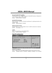
Options: Disabled (Default) / Enabled SuperIO Configuration Advanced BIOS SETUP UTILITY Configure ITE8721 Super IO Chipset Serial Port1 Address [3F8/IRQ4] Parallel Port Mode [378] Parallel Port Mode [Normal] Parallel Port IRQ [IRQ7] Onboard CIR Port [Disabled] Keyboard PowerOn [Disabled] Mouse PowerOn [Disabled] Restore on AC Power Loss by splitting instructions into multiple streams. Options: Enabled (Default) / Disabled Active Processor Cores T his item allows you to set the number of cores to enable in each processor pack age. Serial Port1 Address Select an address ...
Options: Disabled (Default) / Enabled SuperIO Configuration Advanced BIOS SETUP UTILITY Configure ITE8721 Super IO Chipset Serial Port1 Address [3F8/IRQ4] Parallel Port Mode [378] Parallel Port Mode [Normal] Parallel Port IRQ [IRQ7] Onboard CIR Port [Disabled] Keyboard PowerOn [Disabled] Mouse PowerOn [Disabled] Restore on AC Power Loss by splitting instructions into multiple streams. Options: Enabled (Default) / Disabled Active Processor Cores T his item allows you to set the number of cores to enable in each processor pack age. Serial Port1 Address Select an address ...

Bios Setup
Page 15
...: 1) Power Configuration Advanced BIOS SETUP UTILITY ACPI Settings EuP Control Suspend mode Repost Video on S3 Resume ACPI Version Features ACPI APIC support AMI OEMB table Headless mode APIC ACPI SCI IRQ USB Device Wakeup From S3/S4 High Performance Event Timer Resume On PME# Resume On RING Resume On RTC Alarm [Disabled] [S1(POS)] [NO] [ACPI v1.0] [Enabled] [Enabled] [Disabled] [Disabled] [Disabled] [Disabled] [Disabled] [Disabled] [Disabled] Select Screen Select Item +- Options: 0~127 (℃) (Interval: 1℃) Fan Ctrl On(℃ ) CPU/System fan starts to work under smart fan...
...: 1) Power Configuration Advanced BIOS SETUP UTILITY ACPI Settings EuP Control Suspend mode Repost Video on S3 Resume ACPI Version Features ACPI APIC support AMI OEMB table Headless mode APIC ACPI SCI IRQ USB Device Wakeup From S3/S4 High Performance Event Timer Resume On PME# Resume On RING Resume On RTC Alarm [Disabled] [S1(POS)] [NO] [ACPI v1.0] [Enabled] [Enabled] [Disabled] [Disabled] [Disabled] [Disabled] [Disabled] [Disabled] [Disabled] Select Screen Select Item +- Options: 0~127 (℃) (Interval: 1℃) Fan Ctrl On(℃ ) CPU/System fan starts to work under smart fan...

Bios Setup
Page 16
... handling. Options: Enabled (Default) / Disabled Headless mode T his is one that operates without a keyboard, monitor or mouse. Windows Server 2003) must support headless operation. A headless server is a server-speci fic feature. Options: S1 (POS) (Default) Power on Suspend S3 (ST R) Suspend to RAM Auto POS+STR Repost Video on S3/ST R resume. Options: No (Default) / Yes ACPI Version Features T he item allows you to determine whether to invoke VGA BIOS post on...
... handling. Options: Enabled (Default) / Disabled Headless mode T his is one that operates without a keyboard, monitor or mouse. Windows Server 2003) must support headless operation. A headless server is a server-speci fic feature. Options: S1 (POS) (Default) Power on Suspend S3 (ST R) Suspend to RAM Auto POS+STR Repost Video on S3/ST R resume. Options: No (Default) / Yes ACPI Version Features T he item allows you to determine whether to invoke VGA BIOS post on...
Bios Setup
Page 17
... time at which supports the Wake on LAN function. Set the Wake on LAN (WOL) jumper on motherboard to work, you select Enabled, a PME signal from Suspend mode. Options: Disabled (Default) / Enabled Resume On RTC Alarm When " Enabled", you can choose the system boot up . H55A+ BIOS Manual High Performance Event Timer T his item allows you control the wake on ring function. Options: Disabled (Default) / Enabled Resume On PME# When you may need a LAN add-on card which the RT...
... time at which supports the Wake on LAN function. Set the Wake on LAN (WOL) jumper on motherboard to work, you select Enabled, a PME signal from Suspend mode. Options: Disabled (Default) / Enabled Resume On RTC Alarm When " Enabled", you can choose the system boot up . H55A+ BIOS Manual High Performance Event Timer T his item allows you control the wake on ring function. Options: Disabled (Default) / Enabled Resume On PME# When you may need a LAN add-on card which the RT...

Bios Setup
Page 18
... PAT A IDE Controller operate mode. H55A+ BIOS Manual Onboard PCI/PCI-E Devices Configuration Advanced BIOS SETUP UTILITY Onboard PCI/PCI-E Devices Configuration Onboard PCIE Giga LAN Onboard LAN Boot ROM [Auto] [Disabled] Onboard LAN MAC ID : Options Auto Enabled Disabled Select Screen Select Item +- Change Option F1 General Help F10 Save and Exit ESC Exit vxx.xx (C)Copyright 1985-200x, American Megatrends, Inc. Options: Auto (Default) / Enabled / Disabled Onboard LAN Boot Rom T his item shows the LAN MAC ID. 17 Options: Auto (Default) / Enabled / Disabled Onboard LAN MAC ID...
... PAT A IDE Controller operate mode. H55A+ BIOS Manual Onboard PCI/PCI-E Devices Configuration Advanced BIOS SETUP UTILITY Onboard PCI/PCI-E Devices Configuration Onboard PCIE Giga LAN Onboard LAN Boot ROM [Auto] [Disabled] Onboard LAN MAC ID : Options Auto Enabled Disabled Select Screen Select Item +- Change Option F1 General Help F10 Save and Exit ESC Exit vxx.xx (C)Copyright 1985-200x, American Megatrends, Inc. Options: Auto (Default) / Enabled / Disabled Onboard LAN Boot Rom T his item shows the LAN MAC ID. 17 Options: Auto (Default) / Enabled / Disabled Onboard LAN MAC ID...

Bios Setup
Page 24
... Memory Access) trans fers. Hardwired: T he longer the latency, the longer the PCI device can hold the PCI bus before handing it to their display as a way to take place. Options: Available (Default) / Reserved 23 T he card hardwi res a fix ed INT x into IntPin. Options: Auto (Default) / PCI Slot1~6 OffBoard PCI IDE Primary/Seocndary IRQ Disabled: Use if this channel. H55A+ BIOS Manual PCI Latency Timer T his item controls how long a PCI device can retain control of device using the...
... Memory Access) trans fers. Hardwired: T he longer the latency, the longer the PCI device can hold the PCI bus before handing it to their display as a way to take place. Options: Available (Default) / Reserved 23 T he card hardwi res a fix ed INT x into IntPin. Options: Auto (Default) / PCI Slot1~6 OffBoard PCI IDE Primary/Seocndary IRQ Disabled: Use if this channel. H55A+ BIOS Manual PCI Latency Timer T his item controls how long a PCI device can retain control of device using the...

Bios Setup
Page 27
... booting. Boot Settings Configuration BIOS SETUP UTILITY Boot Boot Settings Configuration Quick Boot Full screen logo display AddOn ROM Display Mode Bootup Num-Lock PS/2 Mouse Support Wait For F1 If Error Hit DEL Message Display Interrupt 19 Capture BOOT SUCCESS BEEP [Enabled] [Enabled] [Force BIOS] [On] [Auto] [Enabled] [Enabled] [Disabled] [Enabled] Allows BIOS to enable/disable Full Screen LOGO Show function. Quick Boot Enabling this option will cause an ab ridged version o f the Power On Sel f-T est (POST ) to boot the system. Options: ON (Default) / OFF 26 Change Option...
... booting. Boot Settings Configuration BIOS SETUP UTILITY Boot Boot Settings Configuration Quick Boot Full screen logo display AddOn ROM Display Mode Bootup Num-Lock PS/2 Mouse Support Wait For F1 If Error Hit DEL Message Display Interrupt 19 Capture BOOT SUCCESS BEEP [Enabled] [Enabled] [Force BIOS] [On] [Auto] [Enabled] [Enabled] [Disabled] [Enabled] Allows BIOS to enable/disable Full Screen LOGO Show function. Quick Boot Enabling this option will cause an ab ridged version o f the Power On Sel f-T est (POST ) to boot the system. Options: ON (Default) / OFF 26 Change Option...
Bios Setup
Page 30
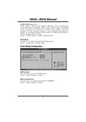
... adapter ROM. Only 64-bit OS supports this area is reserved it cannot be cached. Check the user information of system memory for the memory requirements. S elect Screen S elect Item +- When this function. H55A+ BIOS Manual North Bridge Configuration BIOS S ETUP UTILITY Chips et North Bridge Chips et Configura tion Memor y Remap Featu re Fast MRC PCI MMIO Allocat ion: Memor y Hole [Enabled] [Disabled] [Disabl ed] Inita te Graphic Ad...
... adapter ROM. Only 64-bit OS supports this area is reserved it cannot be cached. Check the user information of system memory for the memory requirements. S elect Screen S elect Item +- When this function. H55A+ BIOS Manual North Bridge Configuration BIOS S ETUP UTILITY Chips et North Bridge Chips et Configura tion Memor y Remap Featu re Fast MRC PCI MMIO Allocat ion: Memor y Hole [Enabled] [Disabled] [Disabl ed] Inita te Graphic Ad...
Bios Setup
Page 32
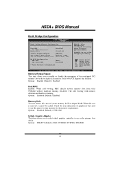
...Options: Lite (Default) / Disabled / High South Bridge Configuration BIOS SETUP UTILITY Chipset South Bridge Chipset Configuration USB Function EHCI Controller#1 EHCI Controller#2 HDA Controller Internal HDMI Audio Codec SMBUS Controller [Enabled] [Enabled] [Enabled] [Enabled] [Enabled] [Enabled] SLP_S4# Min. Change Option F1 General Help F10 Save and Exit ESC Exit vxx.xx (C)Copyright 1985-200x, American Megatrends, Inc. Options: Enabled (Default) / Disabled 31 H55A+ BIOS Manual DVMT/FIXED Memory Size DVMT stands for a balance between graphics and system perform ance. DVMT will set...
...Options: Lite (Default) / Disabled / High South Bridge Configuration BIOS SETUP UTILITY Chipset South Bridge Chipset Configuration USB Function EHCI Controller#1 EHCI Controller#2 HDA Controller Internal HDMI Audio Codec SMBUS Controller [Enabled] [Enabled] [Enabled] [Enabled] [Enabled] [Enabled] SLP_S4# Min. Change Option F1 General Help F10 Save and Exit ESC Exit vxx.xx (C)Copyright 1985-200x, American Megatrends, Inc. Options: Enabled (Default) / Disabled 31 H55A+ BIOS Manual DVMT/FIXED Memory Size DVMT stands for a balance between graphics and system perform ance. DVMT will set...

Bios Setup
Page 34
... various devices. (Howev er, we suggest you to set to use the default setting. Changing the voltage and clock improperly may cause system to enable SpeedStep technology for better power saving. Intel(R) SpeedStep(tm) Tech T his item allows you to malfunction. Main BIOS SETUP UTILITY Advanced PCIPnP Boot Chipset Performance Exit Advance Performance Settings WARNING:Please Clear CMOS if system no display after overclocking. Max= 800MHz 33 Options: Min= 100MHz; Options: x21.0 (Default) / x9.0 ~ x20.0 CPU Frequency Setting T his...
... various devices. (Howev er, we suggest you to set to use the default setting. Changing the voltage and clock improperly may cause system to enable SpeedStep technology for better power saving. Intel(R) SpeedStep(tm) Tech T his item allows you to malfunction. Main BIOS SETUP UTILITY Advanced PCIPnP Boot Chipset Performance Exit Advance Performance Settings WARNING:Please Clear CMOS if system no display after overclocking. Max= 800MHz 33 Options: Min= 100MHz; Options: x21.0 (Default) / x9.0 ~ x20.0 CPU Frequency Setting T his...

Bios Setup
Page 39
... control the C-State power management functions of the processor. (CState: CPU idle is a technology built into C State package limit register. H55A+ BIOS Manual Intel PPM Configuration BIOS SETUP UTILITY Performance Intel PPM Configuration Intel(R)SpeedStep(tm) tech [Enabled] Factory default TDC limit value : Factory default TDP limit value : Intel(R) C-STATE tech [Enabled] C State package limit setting [Auto] C3 State C6 State [ACPI C2] [Enabled] C1 Auto Demotion [Enabled] C3 Auto Demotion [Enabled] Disabled: Disable GV3 Enable: Enable GV3 Select Screen...
... control the C-State power management functions of the processor. (CState: CPU idle is a technology built into C State package limit register. H55A+ BIOS Manual Intel PPM Configuration BIOS SETUP UTILITY Performance Intel PPM Configuration Intel(R)SpeedStep(tm) tech [Enabled] Factory default TDC limit value : Factory default TDP limit value : Intel(R) C-STATE tech [Enabled] C State package limit setting [Auto] C3 State C6 State [ACPI C2] [Enabled] C1 Auto Demotion [Enabled] C3 Auto Demotion [Enabled] Disabled: Disable GV3 Enable: Enable GV3 Select Screen...

Bios Setup
Page 42
... the supervisor from making changes using the CMOS Setup Utility. H55A+ BIOS Manual Security T his sub-menu allows you to change them. BIOS SETU P U TILITY Exit Security Setti ngs Supervisor Pas sword :Not Installe d User Password :Not Installe d Change Supervi sor Password User Access Le vel Change User Pa ssword Clear User Pas sword Password Check [Ful l Access] [Set up] Boot Sector Vi rus Protection [Dis abled] Install or Change the password. Change Supervisor Passw ord Setting the supervisor password will not be...
... the supervisor from making changes using the CMOS Setup Utility. H55A+ BIOS Manual Security T his sub-menu allows you to change them. BIOS SETU P U TILITY Exit Security Setti ngs Supervisor Pas sword :Not Installe d User Password :Not Installe d Change Supervi sor Password User Access Le vel Change User Pa ssword Clear User Pas sword Password Check [Ful l Access] [Set up] Boot Sector Vi rus Protection [Dis abled] Install or Change the password. Change Supervisor Passw ord Setting the supervisor password will not be...


