Owners Manual
Page 2
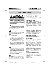
...SAFETY INFORMATION • When connecting or disconnecting the AC power cord, grip the plug and not the cord itself. Let the unit stand for a long period of time, disconnect the AC power cord. These limits are not going to the presence of important operating and...(servicing) instructions in the literature accompanying the appliance. Reorient or relocate the receiving antenna. - Consult the dealer or an experienced radio/TV technician for Class II (Double Insulation) CAUTION • DANGER OF EXPLOSION IF BATTERY IS INCORRECTLY REPLACED. REFER SERVICING TO QUALIFIED SERVICE ...
...SAFETY INFORMATION • When connecting or disconnecting the AC power cord, grip the plug and not the cord itself. Let the unit stand for a long period of time, disconnect the AC power cord. These limits are not going to the presence of important operating and...(servicing) instructions in the literature accompanying the appliance. Reorient or relocate the receiving antenna. - Consult the dealer or an experienced radio/TV technician for Class II (Double Insulation) CAUTION • DANGER OF EXPLOSION IF BATTERY IS INCORRECTLY REPLACED. REFER SERVICING TO QUALIFIED SERVICE ...
Owners Manual
Page 3
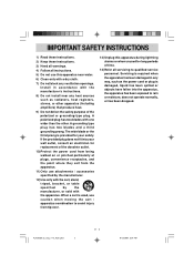
... defect the safety purpose of time. 14)Refer all instructions. 5) Do not use attachments / accessories specified by the manufacturer. 12)Use only with the cart, stand, tripod, bracket, or table specified by the manufacturer, or sold with one wider than the other.
... defect the safety purpose of time. 14)Refer all instructions. 5) Do not use attachments / accessories specified by the manufacturer. 12)Use only with the cart, stand, tripod, bracket, or table specified by the manufacturer, or sold with one wider than the other.

Owners Manual
Page 4
... SAFETY PRECAUTIONS ...1 IMPORTANT SAFETY INSTRUCTIONS 2 CONTENTS ...3 ACCESSORIES ...4 GETTING STARTED ...4 CONTROL REFERENCE GUIDE 5 - 7 CONNECTIONS ...8 - 12 Connecting a TV Antenna / Cable / Satellite 8 Connecting an A / V Device ...8 Connecting Devices with a Composite (Yellow RCA-Type) Video Output 9 Connecting ......11 Connecting the AC Power Cord 12 USING HEADPHONES ...12 INSTALLATION ...13 Removing the Base Stand ...13 Mounting on the Wall ...13 TV SETUP ...14 - 19 Video Menu ...14 Audio Menu ...15 TV Menu ...16 Setup Menu ...17 - 18 Parental Menu ...18 - 19 TROUBLESHOOTING GUIDE ...
... SAFETY PRECAUTIONS ...1 IMPORTANT SAFETY INSTRUCTIONS 2 CONTENTS ...3 ACCESSORIES ...4 GETTING STARTED ...4 CONTROL REFERENCE GUIDE 5 - 7 CONNECTIONS ...8 - 12 Connecting a TV Antenna / Cable / Satellite 8 Connecting an A / V Device ...8 Connecting Devices with a Composite (Yellow RCA-Type) Video Output 9 Connecting ......11 Connecting the AC Power Cord 12 USING HEADPHONES ...12 INSTALLATION ...13 Removing the Base Stand ...13 Mounting on the Wall ...13 TV SETUP ...14 - 19 Video Menu ...14 Audio Menu ...15 TV Menu ...16 Setup Menu ...17 - 18 Parental Menu ...18 - 19 TROUBLESHOOTING GUIDE ...
Owners Manual
Page 7
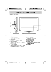
STD.BY / ON button Turns the unit on the TV menu screen and changes the TV channels. 5. - Removable stand 7. Standby indicator 9. CH buttons Confirms selections on and off. 2. Color LCD screen 8. FUNCTION button Selects TV / AV 1 / AV 2 / YUV in / HDMI 1 / HDMI 2 / PC in. 4. CONTROL REFERENCE GUIDE FRONT & SIDE VIEWS 1. MENU button Enters the on-screen TV menu. 3. Speaker PLV36260_ib_eng_1-13_AUD.pmd 6 E - 6 9/13/2007, 3:24 PM Remote sensor Receives the remote control signal. VOL + controls Adjusts the volume level. 6.
STD.BY / ON button Turns the unit on the TV menu screen and changes the TV channels. 5. - Removable stand 7. Standby indicator 9. CH buttons Confirms selections on and off. 2. Color LCD screen 8. FUNCTION button Selects TV / AV 1 / AV 2 / YUV in / HDMI 1 / HDMI 2 / PC in. 4. CONTROL REFERENCE GUIDE FRONT & SIDE VIEWS 1. MENU button Enters the on-screen TV menu. 3. Speaker PLV36260_ib_eng_1-13_AUD.pmd 6 E - 6 9/13/2007, 3:24 PM Remote sensor Receives the remote control signal. VOL + controls Adjusts the volume level. 6.
Owners Manual
Page 14
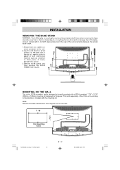
... (such as a blanket or thick piece of the unit at all times when removing the base stand. Remove the 8 screws and then remove the BASE STAND from the unit. INSTALLATION REMOVING THE BASE STAND WARNING: The LCD display is very fragile, and must be wall-mounted with a VESA-compliant 7 7/8" x 3 ...7/8" (200mm x 100mm) mounting kit designed for flat-panel TVs (sold separately). Be sure that no hard ...
... (such as a blanket or thick piece of the unit at all times when removing the base stand. Remove the 8 screws and then remove the BASE STAND from the unit. INSTALLATION REMOVING THE BASE STAND WARNING: The LCD display is very fragile, and must be wall-mounted with a VESA-compliant 7 7/8" x 3 ...7/8" (200mm x 100mm) mounting kit designed for flat-panel TVs (sold separately). Be sure that no hard ...

