
Motherboard DIY Troubleshooting Guide
Page 1
P4SP-MX Motherboard
P4SP-MX Motherboard

P4SP-MX User Manual
Page 1
Motherboard P4SP-MX User Guide
Motherboard P4SP-MX User Guide
P4SP-MX User Manual
Page 3
... v Safety information vi P4SP-MX specification summary vii About this guide viii Chapter 1: Product introduction 1.1 Welcome 1-2 1.2 Package contents 1-2 1.3 Special features 1-2 1.3.1 Product highlights 1-2 1.3.2 ASUS unique features 1-4 1.4 Before you proceed 1-5 1.5 Motherboard overview 1-6 1.5.1 Motherboard layout 1-6 1.5.2 Placement direction 1-7 1.5.3 Screw holes 1-7 1.6 Central Processing Unit (CPU 1-8 1.6.1 Overview 1-8 1.6.2 Installing the CPU 1-9 1.7 System memory 1-10 1.7.1 1.7.2 1.7.3 1.7.4 DIMM sockets location 1-10 Memory configurations...
... v Safety information vi P4SP-MX specification summary vii About this guide viii Chapter 1: Product introduction 1.1 Welcome 1-2 1.2 Package contents 1-2 1.3 Special features 1-2 1.3.1 Product highlights 1-2 1.3.2 ASUS unique features 1-4 1.4 Before you proceed 1-5 1.5 Motherboard overview 1-6 1.5.1 Motherboard layout 1-6 1.5.2 Placement direction 1-7 1.5.3 Screw holes 1-7 1.6 Central Processing Unit (CPU 1-8 1.6.1 Overview 1-8 1.6.2 Installing the CPU 1-9 1.7 System memory 1-10 1.7.1 1.7.2 1.7.3 1.7.4 DIMM sockets location 1-10 Memory configurations...

P4SP-MX User Manual
Page 6
... you are not sure about the voltage of the electrical outlet you add a device. • Before connecting or removing signal cables from the motherboard, ensure that all cables are correctly connected and the power cables are connected. Do not place the product in your local power company. •.... • Before using the product, make sure all power cables are using an adpater or extension cord. Operation safety • Before installing the motherboard and adding devices on a stable surface. • If you detect any area where it may become wet. • Place the product on it...
... you are not sure about the voltage of the electrical outlet you add a device. • Before connecting or removing signal cables from the motherboard, ensure that all cables are correctly connected and the power cables are connected. Do not place the product in your local power company. •.... • Before using the product, make sure all power cables are using an adpater or extension cord. Operation safety • Before installing the motherboard and adding devices on a stable surface. • If you detect any area where it may become wet. • Place the product on it...

P4SP-MX User Manual
Page 9
Chapter 1 This chapter describes the features of the layout, jumper settings, and connectors. It includes brief descriptions of the motherboard components, and illustrations of the motherboard. Product introduction
Chapter 1 This chapter describes the features of the layout, jumper settings, and connectors. It includes brief descriptions of the motherboard components, and illustrations of the motherboard. Product introduction

P4SP-MX User Manual
Page 10
... Product introduction The P4SP-MX also supports the next-generation Intel® Prescott CPU and the Intel® Hyper-Threading Technology. The ASUS P4SP-MX motherboard delivers a host of new features and latest technologies making it , check the items in your P4SP-MX package for the Intel®...list below. 1.2 Package contents Check your package with a 478-pin surface mount, Zero Insertion Force (ZIF) socket for the following items. ASUS P4SP-MX motherboard Micro-ATX form factor: 9.6 in x 9.6 in the long line of the above items is the SiS651/962L chipset that allows 4.3GB/s...
... Product introduction The P4SP-MX also supports the next-generation Intel® Prescott CPU and the Intel® Hyper-Threading Technology. The ASUS P4SP-MX motherboard delivers a host of new features and latest technologies making it , check the items in your P4SP-MX package for the Intel®...list below. 1.2 Package contents Check your package with a 478-pin surface mount, Zero Insertion Force (ZIF) socket for the following items. ASUS P4SP-MX motherboard Micro-ATX form factor: 9.6 in x 9.6 in the long line of the above items is the SiS651/962L chipset that allows 4.3GB/s...

P4SP-MX User Manual
Page 11
... Intel® Pentium® 4 processor, and supports a 2D/3D graphic engine, memory controller, AGP 4X, and 533MHz front side bus. ASUS P4SP-MX motherboard user guide 1-3 See page 2-19. USB 2.0 connectivity The motherboard rear panel is a subsystem that integrates various I /O. This speed advantage over the conventional USB 1.1 (12 Mbps) allows faster Internet connection...
... Intel® Pentium® 4 processor, and supports a 2D/3D graphic engine, memory controller, AGP 4X, and 533MHz front side bus. ASUS P4SP-MX motherboard user guide 1-3 See page 2-19. USB 2.0 connectivity The motherboard rear panel is a subsystem that integrates various I /O. This speed advantage over the conventional USB 1.1 (12 Mbps) allows faster Internet connection...

P4SP-MX User Manual
Page 12
... products, ASUS motherboards now enable users to enjoy this protection feature without the need to use a DOS-based utility or boot from a floppy diskette even when BIOS code and data are corrupted during upgrade or invaded by a virus. See page 2-3. 1-4 Chapter 1: Product introduction See page 2-6. ASUS EZ Flash... BIOS With the ASUS EZ Flash, you can easily update the system BIOS even before loading the operating system. No need to pay for an ...
... products, ASUS motherboards now enable users to enjoy this protection feature without the need to use a DOS-based utility or boot from a floppy diskette even when BIOS code and data are corrupted during upgrade or invaded by a virus. See page 2-3. 1-4 Chapter 1: Product introduction See page 2-6. ASUS EZ Flash... BIOS With the ASUS EZ Flash, you can easily update the system BIOS even before loading the operating system. No need to pay for an ...

P4SP-MX User Manual
Page 13
...on a grounded antistatic pad or in the bag that came with a stand-by the edges to avoid touching the ICs on them due to the motherboard, peripherals, and/or components. Failure to do so may cause severe damage to static electricity. • Hold components by power LED. 1.4 Before ... Take note of the onboard LED. ® P4SP-MX P4SP-MX Onboard LED SB_PWR1 ON Standby Power OFF Powered Off ASUS P4SP-MX motherboard user guide 1-5 Onboard LED The motherboard comes with the component. • Before you install or remove any component, ensure that you should shut down the system...
...on a grounded antistatic pad or in the bag that came with a stand-by the edges to avoid touching the ICs on them due to the motherboard, peripherals, and/or components. Failure to do so may cause severe damage to static electricity. • Hold components by power LED. 1.4 Before ... Take note of the onboard LED. ® P4SP-MX P4SP-MX Onboard LED SB_PWR1 ON Standby Power OFF Powered Off ASUS P4SP-MX motherboard user guide 1-5 Onboard LED The motherboard comes with the component. • Before you install or remove any component, ensure that you should shut down the system...

P4SP-MX User Manual
Page 14
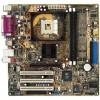
Socket 478 DDR DIMM1 (64/72 bit, 184-pin module) DDR DIMM2 (64/72 bit, 184-pin module) SEC_IDE1 PRI_IDE1 24.4cm (9.6in) 1.5 Motherboard overview 1.5.1 Motherboard layout 24.4cm (9.6in) PS/2KBMS T: Mouse B: Keyboard USBPWR_34 USBPWR_12 SPDIF1 CPU_FAN1 ATX Power Connector PARALLEL PORT VGA1 USB20_12 Bottom: USB3 USB4 Top: RJ-45 ...
Socket 478 DDR DIMM1 (64/72 bit, 184-pin module) DDR DIMM2 (64/72 bit, 184-pin module) SEC_IDE1 PRI_IDE1 24.4cm (9.6in) 1.5 Motherboard overview 1.5.1 Motherboard layout 24.4cm (9.6in) PS/2KBMS T: Mouse B: Keyboard USBPWR_34 USBPWR_12 SPDIF1 CPU_FAN1 ATX Power Connector PARALLEL PORT VGA1 USB20_12 Bottom: USB3 USB4 Top: RJ-45 ...

P4SP-MX User Manual
Page 15
Doing so may damage the motherboard. 1.5.2 Placement direction When installing the motherboard, make sure that you place it into the holes indicated by circles to secure the motherboard to the rear part of the chassis ASUS P4SP-MX motherboard user guide 1-7 Do not overtighten the screws! Place this side towards the rear of the chassis as indicated in the image below. 1.5.3 Screw holes Place eight (8) screws into the chassis in the correct orientation. The edge with external ports goes to the chassis.
Doing so may damage the motherboard. 1.5.2 Placement direction When installing the motherboard, make sure that you place it into the holes indicated by circles to secure the motherboard to the rear part of the chassis ASUS P4SP-MX motherboard user guide 1-7 Do not overtighten the screws! Place this side towards the rear of the chassis as indicated in the image below. 1.5.3 Screw holes Place eight (8) screws into the chassis in the correct orientation. The edge with external ports goes to the chassis.

P4SP-MX User Manual
Page 17
...these steps to a 90°- 100° angle. Locate the 478-pin ZIF socket on the motherboard. The CPU fits only in place, push down the socket lever to the CPU_FAN1 connector on the motherboard. 2. Carefully insert the CPU into the socket to indicate that came with the heatsink package. 7. ...DO NOT force the CPU into the socket until it fits in completely. 90 - 100 3. Gold Mark ASUS P4SP-MX motherboard user guide 1-9 Install a CPU heatsink and fan following the instructions that it up to 90°-100° angle, otherwise the CPU does ...
...these steps to a 90°- 100° angle. Locate the 478-pin ZIF socket on the motherboard. The CPU fits only in place, push down the socket lever to the CPU_FAN1 connector on the motherboard. 2. Carefully insert the CPU into the socket to indicate that came with the heatsink package. 7. ...DO NOT force the CPU into the socket until it fits in completely. 90 - 100 3. Gold Mark ASUS P4SP-MX motherboard user guide 1-9 Install a CPU heatsink and fan following the instructions that it up to 90°-100° angle, otherwise the CPU does ...

P4SP-MX User Manual
Page 18
... the memory modules first. Long AGP cards, when installed, may interfere with the memory sockets. 1.7.2 Memory configurations You may cause severe damage to both the motherboard and the components. • When installing long AGP cards, it is recommended to unplug the power supply before adding or removing DIMMs or other system...
... the memory modules first. Long AGP cards, when installed, may interfere with the memory sockets. 1.7.2 Memory configurations You may cause severe damage to both the motherboard and the components. • When installing long AGP cards, it is recommended to unplug the power supply before adding or removing DIMMs or other system...

P4SP-MX User Manual
Page 19
... Retaining Clip 1.7.4 Removing a DIMM Follow these steps to remove a DIMM. 1. Follow these steps to install a DIMM. 1. Firmly insert the DIMM into a socket to both the motherboard and the components. 1.7.3 Installing a DIMM Make sure to unlock the DIMM. Unlocked retaining clip 3. Failure to do so may cause severe damage to avoid damaging...
... Retaining Clip 1.7.4 Removing a DIMM Follow these steps to remove a DIMM. 1. Follow these steps to install a DIMM. 1. Firmly insert the DIMM into a socket to both the motherboard and the components. 1.7.3 Installing a DIMM Make sure to unlock the DIMM. Unlocked retaining clip 3. Failure to do so may cause severe damage to avoid damaging...

P4SP-MX User Manual
Page 20
... BIOS settings, if any. Assign an IRQ to the chassis with the screw you removed earlier. 6. Remove the system unit cover (if your motherboard is completely seated on the next page. 3. Secure the card to the card. Keep the screw for the expansion card. 1-12 Chapter 1:...the power cord before adding or removing expansion cards. 1.8 Expansion slots In the future, you may cause you physical injury and damage motherboard components. 1.8.1 Installing an expansion card Follow these steps to install an expansion card. 1. Align the card connector with it by adjusting the ...
... BIOS settings, if any. Assign an IRQ to the chassis with the screw you removed earlier. 6. Remove the system unit cover (if your motherboard is completely seated on the next page. 3. Secure the card to the card. Keep the screw for the expansion card. 1-12 Chapter 1:...the power cord before adding or removing expansion cards. 1.8 Expansion slots In the future, you may cause you physical injury and damage motherboard components. 1.8.1 Installing an expansion card Follow these steps to install an expansion card. 1. Align the card connector with it by adjusting the ...
P4SP-MX User Manual
Page 21
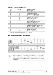
... - - - - PCI slot 2 - - shared - - PCI slot 3 - - - used - - - IRQ assignments for ISA or PCI devices. ASUS P4SP-MX motherboard user guide 1-13 Standard interrupt assignments IRQ Priority Standard Function 0 1 System Timer 1 2 Keyboard Controller 2 N/A Programmable Interrupt 3* 11 Communications Port (COM2) 4* 12... Port 13 8 Numeric Data Processor 14* 9 Primary IDE Channel 15* 10 Secondary IDE Channel * These IRQs are usually available for this motherboard A B C D E PCI slot 1 - used - - - - - F - - - - - GH used - - ...
... - - - - PCI slot 2 - - shared - - PCI slot 3 - - - used - - - IRQ assignments for ISA or PCI devices. ASUS P4SP-MX motherboard user guide 1-13 Standard interrupt assignments IRQ Priority Standard Function 0 1 System Timer 1 2 Keyboard Controller 2 N/A Programmable Interrupt 3* 11 Communications Port (COM2) 4* 12... Port 13 8 Numeric Data Processor 14* 9 Primary IDE Channel 15* 10 Secondary IDE Channel * These IRQs are usually available for this motherboard A B C D E PCI slot 1 - used - - - - - F - - - - - GH used - - ...

P4SP-MX User Manual
Page 22
... the notches on the card golden fingers to ensure that you buy an AGP card, make sure that they fit the AGP slot on the motherboard. This motherboard does not support 3.3V AGP cards. 1.8.3 PCI slots The PCI slots support PCI cards such as a LAN card, SCSI card, USB card, and other...
... the notches on the card golden fingers to ensure that you buy an AGP card, make sure that they fit the AGP slot on the motherboard. This motherboard does not support 3.3V AGP cards. 1.8.3 PCI slots The PCI slots support PCI cards such as a LAN card, SCSI card, USB card, and other...

P4SP-MX User Manual
Page 23
.... Removing the cap will cause system boot failure! ® P4SP-MX CLRTC1 12 23 Normal (Default) Clear CMOS P4SP-MX Clear RTC RAM Setting ASUS P4SP-MX motherboard user guide 1-15 To erase the RTC RAM: 1. Move the jumper cap from pins 1-2 (default) to clear the Real Time Clock (RTC) RAM in...
.... Removing the cap will cause system boot failure! ® P4SP-MX CLRTC1 12 23 Normal (Default) Clear CMOS P4SP-MX Clear RTC RAM Setting ASUS P4SP-MX motherboard user guide 1-15 To erase the RTC RAM: 1. Move the jumper cap from pins 1-2 (default) to clear the Real Time Clock (RTC) RAM in...

P4SP-MX User Manual
Page 25
... for a PS/2 keyboard. Line Out port. This Mic (pink) port connects a microphone. USB 2.0 ports 1 and 2. S/PDIF port. 1.10 Connectors This section describes and illustrates the motherboard rear panel and internal connectors. 1.10.1 Rear panel connectors 1 2 3 4 5 6 11 10 9 8 7 1. Parallel port. Microphone port. PS/2 keyboard port. VGA port. This purple... Out Windows® 98SE only supports 2-channel speaker configuration. 7. These two 4-pin Universal Serial Bus (USB) ports are available for a PS/2 mouse. 2. ASUS P4SP-MX motherboard user guide 1-17
... for a PS/2 keyboard. Line Out port. This Mic (pink) port connects a microphone. USB 2.0 ports 1 and 2. S/PDIF port. 1.10 Connectors This section describes and illustrates the motherboard rear panel and internal connectors. 1.10.1 Rear panel connectors 1 2 3 4 5 6 11 10 9 8 7 1. Parallel port. Microphone port. PS/2 keyboard port. VGA port. This purple... Out Windows® 98SE only supports 2-channel speaker configuration. 7. These two 4-pin Universal Serial Bus (USB) ports are available for a PS/2 mouse. 2. ASUS P4SP-MX motherboard user guide 1-17

P4SP-MX User Manual
Page 26
... cable is intentional. Floppy disk drive connector (34-1 pin FLOPPY1) This connector supports the provided floppy drive ribbon cable. After connecting one end to the motherboard, connect the other end to the floppy drive. (Pin 5 is removed to match the covered hole on the floppy ribbon cable to PIN 1. This prevents...
... cable is intentional. Floppy disk drive connector (34-1 pin FLOPPY1) This connector supports the provided floppy drive ribbon cable. After connecting one end to the motherboard, connect the other end to the floppy drive. (Pin 5 is removed to match the covered hole on the floppy ribbon cable to PIN 1. This prevents...


