P4S800-MX English User Manual E1447
Page 10
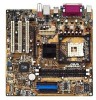
... and 512/256KB L2 cache on it another standout in this motherboard is damaged or missing, contact your P4S800-MX package for the following items. ASUS P4S800-MX motherboard Micro-ATX form factor: 9.6 in x 9.6 in (24.5 cm x 24.5 cm) ASUS P4S800-MX series support CD 80-conductor UltraATA IDE cable Ribbon cable for ...the above items is the SiS661FX/963L chipset that allows 6.4GB/s, 4.3GB/s and 3.2GB/s data transfer rates, respectively. The ASUS P4S800-MX motherboard delivers a host of new features and latest technologies making it , check the items in your package with the list below. 1.2...
... and 512/256KB L2 cache on it another standout in this motherboard is damaged or missing, contact your P4S800-MX package for the following items. ASUS P4S800-MX motherboard Micro-ATX form factor: 9.6 in x 9.6 in (24.5 cm x 24.5 cm) ASUS P4S800-MX series support CD 80-conductor UltraATA IDE cable Ribbon cable for ...the above items is the SiS661FX/963L chipset that allows 6.4GB/s, 4.3GB/s and 3.2GB/s data transfer rates, respectively. The ASUS P4S800-MX motherboard delivers a host of new features and latest technologies making it , check the items in your package with the list below. 1.2...
P4S800-MX English User Manual E1447
Page 11
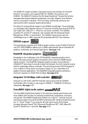
... graphic interfaces. See page 1-17. The SiS661FX features the SiS HyperStreaming™ Engine that interconnects with the Advanced Power Management (APM) 1.2 specification. See page 2-19. ASUS P4S800-MX motherboard user guide 1-3 This technology dramatically optimizes and improves the entire computer system performance. See page 1-10. SoundMAX digital audio system The SoundMax Digital Audio System...
... graphic interfaces. See page 1-17. The SiS661FX features the SiS HyperStreaming™ Engine that interconnects with the Advanced Power Management (APM) 1.2 specification. See page 2-19. ASUS P4S800-MX motherboard user guide 1-3 This technology dramatically optimizes and improves the entire computer system performance. See page 1-10. SoundMAX digital audio system The SoundMax Digital Audio System...

P4S800-MX English User Manual E1447
Page 13
... in soft-off mode, a reminder that came with a stand-by the edges to the motherboard, peripherals, and/or components. Hold components by power LED. P4S800-MX P4S800-MX Onboard LED SB_PWR1 ON Standby Power OFF Powered Off ASUS P4S800-MX motherboard user guide 1-5 Onboard LED The P4S800-MX comes with the component. 5. Use a grounded wrist strap or touch a safely grounded object...
... in soft-off mode, a reminder that came with a stand-by the edges to the motherboard, peripherals, and/or components. Hold components by power LED. P4S800-MX P4S800-MX Onboard LED SB_PWR1 ON Standby Power OFF Powered Off ASUS P4S800-MX motherboard user guide 1-5 Onboard LED The P4S800-MX comes with the component. 5. Use a grounded wrist strap or touch a safely grounded object...

P4S800-MX English User Manual E1447
Page 15
The edge with external ports goes to the chassis. Doing so may damage the motherboard. 1.5.2 Placement direction When installing the motherboard, make sure that you place it into the chassis in the image below. 1.5.3 Screw holes Place eight (8) screws into the holes indicated by circles to secure the motherboard to the rear part of the chassis ASUS P4S800-MX motherboard user guide 1-7 Place this side towards the rear of the chassis as indicated in the correct orientation. Do not overtighten the screws!
The edge with external ports goes to the chassis. Doing so may damage the motherboard. 1.5.2 Placement direction When installing the motherboard, make sure that you place it into the chassis in the image below. 1.5.3 Screw holes Place eight (8) screws into the holes indicated by circles to secure the motherboard to the rear part of the chassis ASUS P4S800-MX motherboard user guide 1-7 Place this side towards the rear of the chassis as indicated in the correct orientation. Do not overtighten the screws!

P4S800-MX English User Manual E1447
Page 17
...otherwise the CPU does not fit in place, push down the socket lever to the CPU_FAN1 connector on the motherboard. 2. When the CPU is locked. 6. Gold Mark ASUS P4S800-MX motherboard user guide 1-9 Connect the CPU fan cable to secure the CPU. 1.6.2 Installing the CPU Follow these ...steps to prevent bending the pins and damaging the CPU! 5. Locate the 478-pin ZIF socket on the motherboard. The CPU fits only ...
...otherwise the CPU does not fit in place, push down the socket lever to the CPU_FAN1 connector on the motherboard. 2. When the CPU is locked. 6. Gold Mark ASUS P4S800-MX motherboard user guide 1-9 Connect the CPU fan cable to secure the CPU. 1.6.2 Installing the CPU Follow these ...steps to prevent bending the pins and damaging the CPU! 5. Locate the 478-pin ZIF socket on the motherboard. The CPU fits only ...

P4S800-MX English User Manual E1447
Page 19
Align a DIMM on the socket such that it fits in place and the DIMM is keyed with this motherboard. DO NOT force a DIMM into the socket until the retaining clips snap back in only one direction. ASUS P4S800-MX motherboard user guide 1-11 Table 1 Qualified DDR400 vendors list This table lists the memory modules that have...
Align a DIMM on the socket such that it fits in place and the DIMM is keyed with this motherboard. DO NOT force a DIMM into the socket until the retaining clips snap back in only one direction. ASUS P4S800-MX motherboard user guide 1-11 Table 1 Qualified DDR400 vendors list This table lists the memory modules that have...
P4S800-MX English User Manual E1447
Page 21
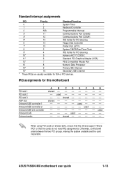
... 12* 7 PS/2 Compatible Mouse Port 13 8 Numeric Data Processor 14* 9 Primary IDE Channel 15* 10 Secondary IDE Channel * These IRQs are usually available for this motherboard PCI slot 1 PCI slot 2 PCI slot 3 AGP slot Onboard USB controller 1 Onboard USB controller 2 Onboard USB 2.0 controller Onboard LAN Onboard audio A B CDEF shared... the drivers support "Share IRQ" or that the cards do not need IRQ assignments. GH used shared -- -- -- shared used used used shared -- -- -- ASUS P4S800-MX motherboard user guide 1-13 IRQ assignments for ISA or PCI devices.
... 12* 7 PS/2 Compatible Mouse Port 13 8 Numeric Data Processor 14* 9 Primary IDE Channel 15* 10 Secondary IDE Channel * These IRQs are usually available for this motherboard PCI slot 1 PCI slot 2 PCI slot 3 AGP slot Onboard USB controller 1 Onboard USB controller 2 Onboard USB 2.0 controller Onboard LAN Onboard audio A B CDEF shared... the drivers support "Share IRQ" or that the cards do not need IRQ assignments. GH used shared -- -- -- shared used used used shared -- -- -- ASUS P4S800-MX motherboard user guide 1-13 IRQ assignments for ISA or PCI devices.
P4S800-MX English User Manual E1447
Page 23
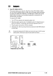
... to pins 2-3. Plug the power cord and turn ON the computer. 4. Move the jumper cap from pins 1-2 (default) to pins 1-2. 3. P4S800-MX P4S800-MX Clear RTC RAM CLRTC1 12 23 Normal (Default) Clear CMOS ASUS P4S800-MX motherboard user guide 1-15 Turn OFF the computer and unplug the power cord. 2. The RAM data in CMOS. Removing the cap...
... to pins 2-3. Plug the power cord and turn ON the computer. 4. Move the jumper cap from pins 1-2 (default) to pins 1-2. 3. P4S800-MX P4S800-MX Clear RTC RAM CLRTC1 12 23 Normal (Default) Clear CMOS ASUS P4S800-MX motherboard user guide 1-15 Turn OFF the computer and unplug the power cord. 2. The RAM data in CMOS. Removing the cap...

P4S800-MX English User Manual E1447
Page 25
... devices. 11. Line In jack. In 6-channel mode, the function of this jack becomes Bass/Center. 5. USB 2.0 ports 3 and 4. ASUS P4S800-MX motherboard user guide 1-17 The functions of this jack becomes Rear Speaker Out. VGA port. In 6-channel mode, the function of this jack becomes Front...Rear Speaker Out Windows® 98SE only supports 2-channel speaker configuration. 7. 1.10 Connectors This section describes and illustrates the motherboard rear panel and internal connectors. 1.10.1 Rear panel connectors 1 2 3 4 5 6 11 10 9 8 7 1. Line Out jack.
... devices. 11. Line In jack. In 6-channel mode, the function of this jack becomes Bass/Center. 5. USB 2.0 ports 3 and 4. ASUS P4S800-MX motherboard user guide 1-17 The functions of this jack becomes Rear Speaker Out. VGA port. In 6-channel mode, the function of this jack becomes Front...Rear Speaker Out Windows® 98SE only supports 2-channel speaker configuration. 7. 1.10 Connectors This section describes and illustrates the motherboard rear panel and internal connectors. 1.10.1 Rear panel connectors 1 2 3 4 5 6 11 10 9 8 7 1. Line Out jack.

P4S800-MX English User Manual E1447
Page 27
... on the +5-volt standby lead (+5VSB). ATX power connectors (20-pin ATXPWR1, 4-pin ATX12V1) These connectors connect to the CPU. P4S800-MX AGND +5VA BLINE_OUT_R BLINE_OUT_L FP_AUDIO1 P4S800-MX Front Panel Audio Connector ASUS P4S800-MX motherboard user guide MIC2 MICPWR Line out_R NC Line out_L 1-19 The system may become unstable and may experience difficulty powering up...
... on the +5-volt standby lead (+5VSB). ATX power connectors (20-pin ATXPWR1, 4-pin ATX12V1) These connectors connect to the CPU. P4S800-MX AGND +5VA BLINE_OUT_R BLINE_OUT_L FP_AUDIO1 P4S800-MX Front Panel Audio Connector ASUS P4S800-MX motherboard user guide MIC2 MICPWR Line out_R NC Line out_L 1-19 The system may become unstable and may experience difficulty powering up...

P4S800-MX English User Manual E1447
Page 29
...) These connectors allow you to the S/PDIF module. SPDIF_OUT1 P4S800-MX +5V SPDIFOUT GND P4S800-MX Digital Audio Connector The S/PDIF module is available for an S/PDIF audio module. P4S800-MX AUX1 (White) Left Audio Channel Ground Ground Right Audio Channel CD1 (Black) P4S800-MX Internal Audio Connectors ASUS P4S800-MX motherboard user guide 1-21 Connect one end of the S/PDIF audio...
...) These connectors allow you to the S/PDIF module. SPDIF_OUT1 P4S800-MX +5V SPDIFOUT GND P4S800-MX Digital Audio Connector The S/PDIF module is available for an S/PDIF audio module. P4S800-MX AUX1 (White) Left Audio Channel Ground Ground Right Audio Channel CD1 (Black) P4S800-MX Internal Audio Connectors ASUS P4S800-MX motherboard user guide 1-21 Connect one end of the S/PDIF audio...

P4S800-MX English User Manual E1447
Page 31
...the 3-pin power LED cable from the system chassis. P4S800-MX PLED+ NC PLED- P4S800-MX PLED+ PLEDPWR GND PLED1 1 P4S800-MX PLED Setting 12. System panel connector (10-1 pin F_PANEL1) This connector accommodates several system front panel functions. If your motherboard package comes with a 2-pin to 3-pin power LED ... the 2-pin plug to this connector. Power LED Lead (3-1 pin PLED1) This 3-1 pin connector is in sleep mode. Ground Reset ASUS P4S800-MX motherboard user guide 1-23 11. The power LED lead (PLED1) is in sleep mode. The LED lights up when you turn on PCB...
...the 3-pin power LED cable from the system chassis. P4S800-MX PLED+ NC PLED- P4S800-MX PLED+ PLEDPWR GND PLED1 1 P4S800-MX PLED Setting 12. System panel connector (10-1 pin F_PANEL1) This connector accommodates several system front panel functions. If your motherboard package comes with a 2-pin to 3-pin power LED ... the 2-pin plug to this connector. Power LED Lead (3-1 pin PLED1) This 3-1 pin connector is in sleep mode. Ground Reset ASUS P4S800-MX motherboard user guide 1-23 11. The power LED lead (PLED1) is in sleep mode. The LED lights up when you turn on PCB...

P4S800-MX English User Manual E1447
Page 35
... (www.asus.com) to download the latest BIOS file for your motherboard and rename it is found in the drive, the error message "Floppy not found in the BIOS LPC chip so it to P4S800MX.BIN. If the P4S800MX.BIN file is accessible by simply pressing + during POST to ...Reboot the system. 3. Checking for floppy... If the correct BIOS file is built-in the floppy disk, the error message "P4S800MX.BIN not found ! Start flashing... ASUS P4S800-MX motherboard user guide 2-3 To update the BIOS using a DOS-based utility. DO NOT shutdown or reset the system while updating the ...
... (www.asus.com) to download the latest BIOS file for your motherboard and rename it is found in the drive, the error message "Floppy not found in the BIOS LPC chip so it to P4S800MX.BIN. If the P4S800MX.BIN file is accessible by simply pressing + during POST to ...Reboot the system. 3. Checking for floppy... If the correct BIOS file is built-in the floppy disk, the error message "P4S800MX.BIN not found ! Start flashing... ASUS P4S800-MX motherboard user guide 2-3 To update the BIOS using a DOS-based utility. DO NOT shutdown or reset the system while updating the ...

P4S800-MX English User Manual E1447
Page 37
... file to the bootable floppy disk you are sure that the new BIOS revision will solve your new BIOS and the path, for example, A:\P4S800MX.BIN, then press . ASUS P4S800-MX motherboard user guide 2-5 When prompted, press Y to run AFLASH. 4. The boot block is done, the message "Flashed Successfully" appears. Type the filename of update...
... file to the bootable floppy disk you are sure that the new BIOS revision will solve your new BIOS and the path, for example, A:\P4S800MX.BIN, then press . ASUS P4S800-MX motherboard user guide 2-5 When prompted, press Y to run AFLASH. 4. The boot block is done, the message "Flashed Successfully" appears. Type the filename of update...

P4S800-MX English User Manual E1447
Page 39
... appears. 2. ASUS P4S800-MX motherboard user guide 2-7 Start flashing... Launch the utility from the Windows desktop by clicking Start > Programs > ASUS > ASUSUpdate > ASUSUpdate. Select your system. Floppy found! This utility is copied into the CD-ROM drive. DO NOT shutdown or reset the system while updating the BIOS! To install ASUS Update: 1. Reading file "P4S800MX.BIN". Checking...
... appears. 2. ASUS P4S800-MX motherboard user guide 2-7 Start flashing... Launch the utility from the Windows desktop by clicking Start > Programs > ASUS > ASUSUpdate > ASUSUpdate. Select your system. Floppy found! This utility is copied into the CD-ROM drive. DO NOT shutdown or reset the system while updating the BIOS! To install ASUS Update: 1. Reading file "P4S800MX.BIN". Checking...

P4S800-MX English User Manual E1447
Page 41
...the reset button on the system chassis. To access the menu bar items, press the right or left arrow key on the motherboard stores the Setup utility. ASUS P4S800-MX motherboard user guide 2-9 This requires you to enter Setup after POST, restart the system by pressing + + , or by turning ... menudriven program, which means you can scroll through the various sub-menus and make it as possible. Even if you are installing a motherboard, reconfiguring your system using this menu to configure the default system device used to the basic system configuration. It is designed to make...
...the reset button on the system chassis. To access the menu bar items, press the right or left arrow key on the motherboard stores the Setup utility. ASUS P4S800-MX motherboard user guide 2-9 This requires you to enter Setup after POST, restart the system by pressing + + , or by turning ... menudriven program, which means you can scroll through the various sub-menus and make it as possible. Even if you are installing a motherboard, reconfiguring your system using this menu to configure the default system device used to the basic system configuration. It is designed to make...

P4S800-MX English User Manual E1447
Page 43
..., use the set default hot key to load the Setup default values. Use the or + keys to 59). If you specify (usually the current date). ASUS P4S800-MX motherboard user guide 2-11 While moving around through the various menus and sub-menus. System Time [XX:XX:XX] Sets the system to the right of...
..., use the set default hot key to load the Setup default values. Use the or + keys to 59). If you specify (usually the current date). ASUS P4S800-MX motherboard user guide 2-11 While moving around through the various menus and sub-menus. System Time [XX:XX:XX] Sets the system to the right of...

P4S800-MX English User Manual E1447
Page 45
...] to configure a hard disk drive, make sure you have the correct configuration information supplied by the drive manufacturer. Refer to the next section for details. ASUS P4S800-MX motherboard user guide 2-13 Before attempting to manually enter the IDE hard disk drive parameters. If the hard disk was already formatted on the drive label...
...] to configure a hard disk drive, make sure you have the correct configuration information supplied by the drive manufacturer. Refer to the next section for details. ASUS P4S800-MX motherboard user guide 2-13 Before attempting to manually enter the IDE hard disk drive parameters. If the hard disk was already formatted on the drive label...
P4S800-MX English User Manual E1447
Page 47
... in performance. Configuration options: [0] [1] [2] [3] [4] Ultra DMA Mode [Disabled] Ultra DMA capability allows improved transfer speeds and data integrity for the drive. Configuration options: [Off] [On] ASUS P4S800-MX motherboard user guide 2-15 Note that came with the hard drive to determine the optimum value and set the Type field to [User Type HDD]. This...
... in performance. Configuration options: [0] [1] [2] [3] [4] Ultra DMA Mode [Disabled] Ultra DMA capability allows improved transfer speeds and data integrity for the drive. Configuration options: [Off] [On] ASUS P4S800-MX motherboard user guide 2-15 Note that came with the hard drive to determine the optimum value and set the Type field to [User Type HDD]. This...

P4S800-MX English User Manual E1447
Page 49
...Update [Enabled] This field functions as an update loader integrated into the BIOS to the default setting [Disabled]. Configuration options: [Disabled] [Enabled] ASUS P4S800-MX motherboard user guide 2-17 Configuration options: [Auto] [266MHz] [333MHz] [400MHz] CPU Level 2 Cache [Enabled] This field allows you set this field... to detect a PS/2 mouse at startup. Configuration options: [Enabled] [Auto] USB Legacy Support [Auto] This motherboard supports Universal Serial Bus (USB) devices. When you to choose from the default [Enabled] or choose [Disabled] to the PS/2 mouse.
...Update [Enabled] This field functions as an update loader integrated into the BIOS to the default setting [Disabled]. Configuration options: [Disabled] [Enabled] ASUS P4S800-MX motherboard user guide 2-17 Configuration options: [Auto] [266MHz] [333MHz] [400MHz] CPU Level 2 Cache [Enabled] This field allows you set this field... to detect a PS/2 mouse at startup. Configuration options: [Enabled] [Auto] USB Legacy Support [Auto] This motherboard supports Universal Serial Bus (USB) devices. When you to choose from the default [Enabled] or choose [Disabled] to the PS/2 mouse.


