Motherboard DIY Troubleshooting Guide
Page 1
Motherboard P4R800-VM User Guide
Motherboard P4R800-VM User Guide

Motherboard DIY Troubleshooting Guide
Page 3
Features Contents Notices vi Safety information vii About this guide viii P4R800-VM specifications summary ix Chapter 1: Product introduction 1.1 Welcome 1-2 1.2 Package contents 1-2 1.3 Special features 1-2 1.4 Before you proceed 1-5 1.5 Motherboard overview 1-6 1.5.1 Motherboard layout 1-6 1.5.2 Placement direction 1-7 1.5.3 Screw holes 1-7 1.6 Central Processing Unit (CPU 1-8 1.6.1 Overview 1-8 1.6.2 Installing the CPU 1-9 1.7 System memory 1-10 1.7.1 DIMM sockets location 1-10 1.7.2 Memory configurations 1-10 1.7.3 Installing...
Features Contents Notices vi Safety information vii About this guide viii P4R800-VM specifications summary ix Chapter 1: Product introduction 1.1 Welcome 1-2 1.2 Package contents 1-2 1.3 Special features 1-2 1.4 Before you proceed 1-5 1.5 Motherboard overview 1-6 1.5.1 Motherboard layout 1-6 1.5.2 Placement direction 1-7 1.5.3 Screw holes 1-7 1.6 Central Processing Unit (CPU 1-8 1.6.1 Overview 1-8 1.6.2 Installing the CPU 1-9 1.7 System memory 1-10 1.7.1 DIMM sockets location 1-10 1.7.2 Memory configurations 1-10 1.7.3 Installing...

Motherboard DIY Troubleshooting Guide
Page 12
... standout in the 478-pin package with a 478-pin surface mount, Zero Insertion Force (ZIF) socket for buying the ASUS® P4R800-VM motherboard! The ASUS P4R800-VM motherboard delivers a host of new features and latest technologies making it , check the items in your package with the list below.... 1.2 Package contents Check your P4R800-VM package for the following items. ASUS P4R800-VM motherboard Micro-ATX form factor: 9.6 in x 9.6 in (24.5 cm x 24.5 cm) ASUS P4R800-VM series support CD Serial (COM) port module and cable 80-conductor Ultra...
... standout in the 478-pin package with a 478-pin surface mount, Zero Insertion Force (ZIF) socket for buying the ASUS® P4R800-VM motherboard! The ASUS P4R800-VM motherboard delivers a host of new features and latest technologies making it , check the items in your package with the list below.... 1.2 Package contents Check your P4R800-VM package for the following items. ASUS P4R800-VM motherboard Micro-ATX form factor: 9.6 in x 9.6 in (24.5 cm x 24.5 cm) ASUS P4R800-VM series support CD Serial (COM) port module and cable 80-conductor Ultra...
Motherboard DIY Troubleshooting Guide
Page 13
... through a separate TV out module (AV/S). The USB ports and header comply with USB 2.0 specification that supports AGP 8X specification. ASUS P4R800-VM motherboard user guide 1-3 See page 1-20. See page 1-17. The RADEON™ 9100 IGP provides processor interface with 800/533/400 MHz... USB header is the ATI RADEON™ 9200-based 2D/3D graphics engine with USB 1.1. Dual channel DDR400 memory support The motherboard supports single or dual memory architecture for two (2) additional USB ports. SoundMAX digital audio system The SoundMax Digital Audio System is backward...
... through a separate TV out module (AV/S). The USB ports and header comply with USB 2.0 specification that supports AGP 8X specification. ASUS P4R800-VM motherboard user guide 1-3 See page 1-20. See page 1-17. The RADEON™ 9100 IGP provides processor interface with 800/533/400 MHz... USB header is the ATI RADEON™ 9200-based 2D/3D graphics engine with USB 1.1. Dual channel DDR400 memory support The motherboard supports single or dual memory architecture for two (2) additional USB ports. SoundMAX digital audio system The SoundMax Digital Audio System is backward...

Motherboard DIY Troubleshooting Guide
Page 15
Before you install or remove any motherboard component. P4R800-VM P4R800-VM Onboard LED SB_PWR1 ON Standby Power OFF Powered Off ASUS P4R800-VM motherboard user guide 1-5 Unplug the power cord from the power supply. The illustration below shows the location of the following precautions... uninstall any component, place it on them due to a metal object, such as the power supply case, before touching any motherboard settings. 1. Onboard LED The motherboard comes with the component. 5. The green LED lights up to indicates that came with a stand-by the edges to avoid ...
Before you install or remove any motherboard component. P4R800-VM P4R800-VM Onboard LED SB_PWR1 ON Standby Power OFF Powered Off ASUS P4R800-VM motherboard user guide 1-5 Unplug the power cord from the power supply. The illustration below shows the location of the following precautions... uninstall any component, place it on them due to a metal object, such as the power supply case, before touching any motherboard settings. 1. Onboard LED The motherboard comes with the component. 5. The green LED lights up to indicates that came with a stand-by the edges to avoid ...

Motherboard DIY Troubleshooting Guide
Page 16
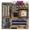
Ground Reset IDE_LED Reset Switch * Requires an ATX power supply. 1-6 Chapter 1: Product introduction 1.5 Motherboard overview 1.5.1 Motherboard layout PS/2KBMS T: Mouse B: Keyboard USB1 USB2 KBPWR1 USBPW12 24.5cm (9.6in) Socket 478 CPU_FAN1 SPDIF_O Super I/O KBPWR1 12 23 +5V (Default)... T: USB3 B: USB4 Top: RJ-45 Top:Line In Center:Line Out Below:Mic In ATX12V1 TV-OUT1 CHA_FAN1 ATI RADEON 9100 IGP P4R800-VM Accelerated Graphics Port (AGP1) RTL 8201BL PCI1 FP_AUDIO1 CD1 AUX1 AD1888 CODEC PCI2 PCI3 USBPW56 ATI IXP200 USB56 COM1 SEC_IDE1 PRI_IDE1 CLRTC1 CR2032...
Ground Reset IDE_LED Reset Switch * Requires an ATX power supply. 1-6 Chapter 1: Product introduction 1.5 Motherboard overview 1.5.1 Motherboard layout PS/2KBMS T: Mouse B: Keyboard USB1 USB2 KBPWR1 USBPW12 24.5cm (9.6in) Socket 478 CPU_FAN1 SPDIF_O Super I/O KBPWR1 12 23 +5V (Default)... T: USB3 B: USB4 Top: RJ-45 Top:Line In Center:Line Out Below:Mic In ATX12V1 TV-OUT1 CHA_FAN1 ATI RADEON 9100 IGP P4R800-VM Accelerated Graphics Port (AGP1) RTL 8201BL PCI1 FP_AUDIO1 CD1 AUX1 AD1888 CODEC PCI2 PCI3 USBPW56 ATI IXP200 USB56 COM1 SEC_IDE1 PRI_IDE1 CLRTC1 CR2032...

Motherboard DIY Troubleshooting Guide
Page 17
The edge with external ports goes to the chassis. Do not overtighten the screws! Doing so may damage the motherboard. 1.5.2 Placement direction When installing the motherboard, make sure that you place it into the chassis in the image below. 1.5.3 Screw holes Place eight (8) screws into the holes indicated by circles to secure the motherboard to the rear part of the chassis ASUS P4R800-VM motherboard user guide 1-7 Place this side towards the rear of the chassis as indicated in the correct orientation.
The edge with external ports goes to the chassis. Do not overtighten the screws! Doing so may damage the motherboard. 1.5.2 Placement direction When installing the motherboard, make sure that you place it into the chassis in the image below. 1.5.3 Screw holes Place eight (8) screws into the holes indicated by circles to secure the motherboard to the rear part of the chassis ASUS P4R800-VM motherboard user guide 1-7 Place this side towards the rear of the chassis as indicated in the correct orientation.

Motherboard DIY Troubleshooting Guide
Page 19
...and fan following the instructions that it fits in place, push down the socket lever to a 90°- 100° angle. Gold Mark ASUS P4R800-VM motherboard user guide 1-9 Connect the CPU fan cable to the CPU_FAN1 connector on the side tab to 90°-100° angle, otherwise the CPU... does not fit in one correct orientation. When the CPU is locked. 6. Locate the 478-pin ZIF socket on the motherboard. 2. Carefully insert the CPU into the socket to install a CPU. 1. 1.6.2 Installing the CPU Follow these steps to prevent bending the pins and ...
...and fan following the instructions that it fits in place, push down the socket lever to a 90°- 100° angle. Gold Mark ASUS P4R800-VM motherboard user guide 1-9 Connect the CPU fan cable to the CPU_FAN1 connector on the side tab to 90°-100° angle, otherwise the CPU... does not fit in one correct orientation. When the CPU is locked. 6. Locate the 478-pin ZIF socket on the motherboard. 2. Carefully insert the CPU into the socket to install a CPU. 1. 1.6.2 Installing the CPU Follow these steps to prevent bending the pins and ...

Motherboard DIY Troubleshooting Guide
Page 20
...Table 1. • A three-DIMM configuration is not supported on sockets of the DDR DIMM sockets. Use any of the recommended configurations in this motherboard • In dual-channel configurations, always install an identical (the same type and size) DDR DIMM pair on this section. DIMM_A1 DIMM_A2 DIMM_B1 ...DIMM_B2 80 Pins 104 Pins P4R800-VM P4R800-VM 184-Pin DDR DIMM Sockets Make sure to do so may interfere with the same CAS latency. Long AGP cards, when installed,...
...Table 1. • A three-DIMM configuration is not supported on sockets of the DDR DIMM sockets. Use any of the recommended configurations in this motherboard • In dual-channel configurations, always install an identical (the same type and size) DDR DIMM pair on this section. DIMM_A1 DIMM_A2 DIMM_B1 ...DIMM_B2 80 Pins 104 Pins P4R800-VM P4R800-VM 184-Pin DDR DIMM Sockets Make sure to do so may interfere with the same CAS latency. Long AGP cards, when installed,...

Motherboard DIY Troubleshooting Guide
Page 21
...-CC4 Samsung 256MB Corsair CM256A-3500C2PT -- 256MB Kingston VALUERAM KVR400X64C25/256 Winbond 256MB Transcend TS32MLD64V4F3 MOSEL Legend: DS - Visit the ASUS website (www.asus.com) for use with this motherboard. Size Vendor Part Number Chip Brand Sides Chip Number 256MB TwinMOS -- Double-sided SS - Table 1: Recommended memory configurations Mode/...DDR400) DIMMs. Table 2: Qualified DDR400 vendors list This table lists the memory modules that have been tested and qualified for the latest QVL. ASUS P4R800-VM motherboard user guide 1-11 Populated - (2) -
...-CC4 Samsung 256MB Corsair CM256A-3500C2PT -- 256MB Kingston VALUERAM KVR400X64C25/256 Winbond 256MB Transcend TS32MLD64V4F3 MOSEL Legend: DS - Visit the ASUS website (www.asus.com) for use with this motherboard. Size Vendor Part Number Chip Brand Sides Chip Number 256MB TwinMOS -- Double-sided SS - Table 1: Recommended memory configurations Mode/...DDR400) DIMMs. Table 2: Qualified DDR400 vendors list This table lists the memory modules that have been tested and qualified for the latest QVL. ASUS P4R800-VM motherboard user guide 1-11 Populated - (2) -

Motherboard DIY Troubleshooting Guide
Page 23
...Otherwise, conflicts will arise between the two PCI groups, making the system unstable and the card inoperable. shared - - - - - - ASUS P4R800-VM motherboard user guide 1-13 1.8.1 Standard interrupt assignments IRQ Priority Standard Function 0 1 System Timer 1 2 Keyboard Controller 2 N/A Programmable Interrupt 3* 11 ... 15* 10 Secondary IDE Channel * These IRQs are usually available for ISA or PCI devices. 1.8.2 IRQ assignments for this motherboard PCI slot 1 PCI slot 2 PCI slot 3 AGP slot Onboard USB controller 1 Onboard USB controller 2 Onboard USB controller ...
...Otherwise, conflicts will arise between the two PCI groups, making the system unstable and the card inoperable. shared - - - - - - ASUS P4R800-VM motherboard user guide 1-13 1.8.1 Standard interrupt assignments IRQ Priority Standard Function 0 1 System Timer 1 2 Keyboard Controller 2 N/A Programmable Interrupt 3* 11 ... 15* 10 Secondary IDE Channel * These IRQs are usually available for ISA or PCI devices. 1.8.2 IRQ assignments for this motherboard PCI slot 1 PCI slot 2 PCI slot 3 AGP slot Onboard USB controller 1 Onboard USB controller 2 Onboard USB controller ...

Motherboard DIY Troubleshooting Guide
Page 24
.... Note the notches on the motherboard. P4R800-VM Keyed for one with PCI specifications. 1.8.4 AGP slot The Accelerated Graphics Port (AGP) slot that they fit the AGP slot on the card golden fingers to ensure that supports AGP 8X/4X (+1.5V) cards. This motherboard does not support 3.3V AGP cards.... 1.8.3 PCI slots The PCI slots support PCI cards such as a LAN card, SCSI card, USB card, and other cards that comply with +1.5V specification. When you buy an AGP card, make sure that you ask for 1.5v P4R800-VM Accelerated...
.... Note the notches on the motherboard. P4R800-VM Keyed for one with PCI specifications. 1.8.4 AGP slot The Accelerated Graphics Port (AGP) slot that they fit the AGP slot on the card golden fingers to ensure that supports AGP 8X/4X (+1.5V) cards. This motherboard does not support 3.3V AGP cards.... 1.8.3 PCI slots The PCI slots support PCI cards such as a LAN card, SCSI card, USB card, and other cards that comply with +1.5V specification. When you buy an AGP card, make sure that you ask for 1.5v P4R800-VM Accelerated...
Motherboard DIY Troubleshooting Guide
Page 25
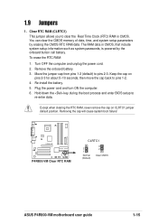
... failure! Clear RTC RAM (CLRTC1) This jumper allows you to pins 1-2. 4. Keep the cap on CLRTC1 jumper default position. P4R800-VM P4R800-VM Clear RTC RAM CLRTC1 2 1 Normal (Default) 3 2 Clear CMOS ASUS P4R800-VM motherboard user guide 1-15 Re-install the battery. 5. You can clear the CMOS memory of date, time, and system setup parameters...
... failure! Clear RTC RAM (CLRTC1) This jumper allows you to pins 1-2. 4. Keep the cap on CLRTC1 jumper default position. P4R800-VM P4R800-VM Clear RTC RAM CLRTC1 2 1 Normal (Default) 3 2 Clear CMOS ASUS P4R800-VM motherboard user guide 1-15 Re-install the battery. 5. You can clear the CMOS memory of date, time, and system setup parameters...
Motherboard DIY Troubleshooting Guide
Page 27
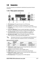
... becomes Rear Speaker Out. The functions of this port becomes Front Speaker Out. 6. S/PDIF out port. USB 2.0 ports 3 and 4. ASUS P4R800-VM motherboard user guide 1-17 RJ-45 port. This port connects a headphone or a speaker. In 6-channel mode, the function of the Line Out...pin port connects a parallel printer or a scanner. 3. This port connects a tape player or other audio sources. 1.10 Connectors This section describes and illustrates the motherboard rear panel and internal connectors. 1.10.1 Rear panel connectors 1 2 3 4 5 6 11 10 9 8 7 1. PS/2 mouse port. Parallel port....
... becomes Rear Speaker Out. The functions of this port becomes Front Speaker Out. 6. S/PDIF out port. USB 2.0 ports 3 and 4. ASUS P4R800-VM motherboard user guide 1-17 RJ-45 port. This port connects a headphone or a speaker. In 6-channel mode, the function of the Line Out...pin port connects a parallel printer or a scanner. 3. This port connects a tape player or other audio sources. 1.10 Connectors This section describes and illustrates the motherboard rear panel and internal connectors. 1.10.1 Rear panel connectors 1 2 3 4 5 6 11 10 9 8 7 1. PS/2 mouse port. Parallel port....

Motherboard DIY Troubleshooting Guide
Page 29
...powering up if the power supply is 230W, or 300W for the ATX power supply. In addition to the 20-pin ATXPWR connector, this motherboard requires that your ATX 12V power supply can provide 8A on the +12V lead and at least 1A on the +5-volt standby lead (+5VSB...). The minimum recommended wattage is inadequate. P4R800-VM CD(Black) AUX(White) Right Audio Channel Ground Ground Left Audio Channel P4R800-VM Internal Audio Connectors ASUS P4R800-VM motherboard user guide 1-19 ATX power connectors (20-pin ATXPWR1, 4-pin ATX12V1) These connectors are ...
...powering up if the power supply is 230W, or 300W for the ATX power supply. In addition to the 20-pin ATXPWR connector, this motherboard requires that your ATX 12V power supply can provide 8A on the +12V lead and at least 1A on the +5-volt standby lead (+5VSB...). The minimum recommended wattage is inadequate. P4R800-VM CD(Black) AUX(White) Right Audio Channel Ground Ground Left Audio Channel P4R800-VM Internal Audio Connectors ASUS P4R800-VM motherboard user guide 1-19 ATX power connectors (20-pin ATXPWR1, 4-pin ATX12V1) These connectors are ...

Motherboard DIY Troubleshooting Guide
Page 30
P4R800-VM TV_OUT1 1 ASUS AV/S P4R800-VM TV Out Connector The ASUS AV/S module is for a front or rear panel I/O board with an audio TV-out port. Connect the fan cables to the fan connectors. CPU_FAN1 Rotation +12V GND P4R800-VM CHA_FAN1 Rotation +12V GND P4R800-VM 12-Volt ...Fan Connectors 1-20 Chapter 1: Product introduction CPU and chassis fan connectors (3-pin CPU_FAN1, CHA_FAN1) The fan connectors support cooling fans of 350mA~740mA (8.88W max.) or a total of sufficient air flow within the system may damage the motherboard...
P4R800-VM TV_OUT1 1 ASUS AV/S P4R800-VM TV Out Connector The ASUS AV/S module is for a front or rear panel I/O board with an audio TV-out port. Connect the fan cables to the fan connectors. CPU_FAN1 Rotation +12V GND P4R800-VM CHA_FAN1 Rotation +12V GND P4R800-VM 12-Volt ...Fan Connectors 1-20 Chapter 1: Product introduction CPU and chassis fan connectors (3-pin CPU_FAN1, CHA_FAN1) The fan connectors support cooling fans of 350mA~740mA (8.88W max.) or a total of sufficient air flow within the system may damage the motherboard...

Motherboard DIY Troubleshooting Guide
Page 31
7. You may install the USB module in the chassis front panel. P4R800-VM SPEAK1 1 +5V GND GND Speak Out P4R800-VM Speaker Out Connector 8. USB+5V USB_P6USB_P6+ GND NC USB+5V USB_P5USB_P5+ GND P4R800-VM USB56 1 P4R800-VM USB 2.0 Header The USB module is available for connecting next generation...USB cable of an optional USB 2.0 module to hear system beeps and warnings. The module has two USB 2.0 ports for additional USB ports. ASUS P4R800-VM motherboard user guide 1-21 USB header (10-1 pin USB56) If the USB ports on the rear panel are inadequate, a USB header is purchased...
7. You may install the USB module in the chassis front panel. P4R800-VM SPEAK1 1 +5V GND GND Speak Out P4R800-VM Speaker Out Connector 8. USB+5V USB_P6USB_P6+ GND NC USB+5V USB_P5USB_P5+ GND P4R800-VM USB56 1 P4R800-VM USB 2.0 Header The USB module is available for connecting next generation...USB cable of an optional USB 2.0 module to hear system beeps and warnings. The module has two USB 2.0 ports for additional USB ports. ASUS P4R800-VM motherboard user guide 1-21 USB header (10-1 pin USB56) If the USB ports on the rear panel are inadequate, a USB header is purchased...

Motherboard DIY Troubleshooting Guide
Page 33
... power, and blinks when the system is for the system power LED. ASUS P4R800-VM motherboard user guide 1-23 System panel connector (10-1 pin F_PANEL1) This connector accommodates several chassis-mounted functions. If your motherboard package comes with a 2-pin to 3-pin power LED converter, connect the... 2-pin plug to the 3-pin power LED plug from the system chassis. Power LED Lead (3-1 pin PLED1) This 3-1 pin connector is in sleep mode. Ground Reset P4R800-VM F_Panel Connector...
... power, and blinks when the system is for the system power LED. ASUS P4R800-VM motherboard user guide 1-23 System panel connector (10-1 pin F_PANEL1) This connector accommodates several chassis-mounted functions. If your motherboard package comes with a 2-pin to 3-pin power LED converter, connect the... 2-pin plug to the 3-pin power LED plug from the system chassis. Power LED Lead (3-1 pin PLED1) This 3-1 pin connector is in sleep mode. Ground Reset P4R800-VM F_Panel Connector...

Motherboard DIY Troubleshooting Guide
Page 37
... any user provided filename of not more than eight (8) alpha-numeric characters for the main filename and three (3) alpha-numeric characters for reference only. ASUS P4R800-VM motherboard user guide 2-3 You can be exactly the same as backup in case the system BIOS file fails or gets corrupted during the flashing process. 2.1.2 Using...
... any user provided filename of not more than eight (8) alpha-numeric characters for the main filename and three (3) alpha-numeric characters for reference only. ASUS P4R800-VM motherboard user guide 2-3 You can be exactly the same as backup in case the system BIOS file fails or gets corrupted during the flashing process. 2.1.2 Using...
Motherboard DIY Troubleshooting Guide
Page 39
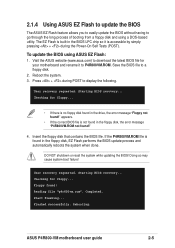
...1. To update the BIOS using a DOS-based utility. Visit the ASUS website (www.asus.com) to download the latest BIOS file for your motherboard and rename it is not found in the BIOS LPC chip so it to P4R800VM.ROM. Reboot the system. 3. Press + during the Power-On Self... + during POST to a floppy disk. 2. Reading file "p4r800vm.rom". Save the BIOS file to display the following. Rebooting. ASUS P4R800-VM motherboard user guide 2-5 The EZ Flash is built-in the floppy disk, the error message "P4R800VM.ROM not found in the floppy disk, EZ Flash performs the...
...1. To update the BIOS using a DOS-based utility. Visit the ASUS website (www.asus.com) to download the latest BIOS file for your motherboard and rename it is not found in the BIOS LPC chip so it to P4R800VM.ROM. Reboot the system. 3. Press + during the Power-On Self... + during POST to a floppy disk. 2. Reading file "p4r800vm.rom". Save the BIOS file to display the following. Rebooting. ASUS P4R800-VM motherboard user guide 2-5 The EZ Flash is built-in the floppy disk, the error message "P4R800VM.ROM not found in the floppy disk, EZ Flash performs the...


