
P4PE2-X User Manual
Page 1
Motherboard P4PE2-X User Guide
Motherboard P4PE2-X User Guide

P4PE2-X User Manual
Page 3
... Notices v Safety information vi About this guide vii P4PE2-X specifications summary viii Chapter 1: Product introduction 1.1 Welcome 1-2 1.2 Package contents 1-2 1.3 Special features 1-2 1.3.1 Product Highlights 1-2 1.3.2 Unique ASUS features 1-3 1.4 Before you proceed 1-4 1.5 Motherboard overview 1-5 1.5.1 Motherboard layout 1-5 1.5.2 Placement direction 1-6 1.5.3 Screw holes 1-6 1.6 Central Processing Unit (CPU 1-7 1.6.1 Overview 1-7 1.6.2 Installing the CPU 1-8 1.7 System memory 1-9 1.7.1 DIMM sockets location 1-9 1.7.2 Memory configurations 1-9 1.7.3 DIMM Qualified...
... Notices v Safety information vi About this guide vii P4PE2-X specifications summary viii Chapter 1: Product introduction 1.1 Welcome 1-2 1.2 Package contents 1-2 1.3 Special features 1-2 1.3.1 Product Highlights 1-2 1.3.2 Unique ASUS features 1-3 1.4 Before you proceed 1-4 1.5 Motherboard overview 1-5 1.5.1 Motherboard layout 1-5 1.5.2 Placement direction 1-6 1.5.3 Screw holes 1-6 1.6 Central Processing Unit (CPU 1-7 1.6.1 Overview 1-7 1.6.2 Installing the CPU 1-8 1.7 System memory 1-9 1.7.1 DIMM sockets location 1-9 1.7.2 Memory configurations 1-9 1.7.3 DIMM Qualified...

P4PE2-X User Manual
Page 6
...of the electrical outlet you are not damaged. Do not place the product in your area. vi Operation safety • Before installing the motherboard and adding devices on a stable surface. • If you encounter technical problems with the package. • Before using the product, make...signal cables are unplugged. • Seek professional assistance before you add a device. • Before connecting or removing signal cables from the motherboard, ensure that all cables are correctly connected and the power cables are using, contact your local power company. • If the power supply...
...of the electrical outlet you are not damaged. Do not place the product in your area. vi Operation safety • Before installing the motherboard and adding devices on a stable surface. • If you encounter technical problems with the package. • Before using the product, make...signal cables are unplugged. • Seek professional assistance before you add a device. • Before connecting or removing signal cables from the motherboard, ensure that all cables are correctly connected and the power cables are using, contact your local power company. • If the power supply...

P4PE2-X User Manual
Page 8
... vendors.) 1 x AGP 4X (1.5V only) 4 x PCI 2 x UltraDMA100/66/33 connectors ADI AD1888 6-channel audio CODEC Realtek® RTL8101L Fast Ethernet controller ASUS JumperFree™ mode ASUS EZ Flash ASUS CrashFree BIOS2 ASUS CPU Parameter Recall (C.P.R.) USB 2.0 ready SFS (Stepless Frequency Selection) Adjustable CPU Vcore 1 x Parallel port 1 x Serial port 1 x PS/2 keyboard port 1 x PS/2 ...MHz (*Overclocked mode, a CPU with 800MHz FSB requires using a PC3200 DIMM) Note: • Intel® Prescott CPUs can only support 533MHz FSB on this motherboard. • 800 MHz FSB works with 800MHz FSB.
... vendors.) 1 x AGP 4X (1.5V only) 4 x PCI 2 x UltraDMA100/66/33 connectors ADI AD1888 6-channel audio CODEC Realtek® RTL8101L Fast Ethernet controller ASUS JumperFree™ mode ASUS EZ Flash ASUS CrashFree BIOS2 ASUS CPU Parameter Recall (C.P.R.) USB 2.0 ready SFS (Stepless Frequency Selection) Adjustable CPU Vcore 1 x Parallel port 1 x Serial port 1 x PS/2 keyboard port 1 x PS/2 ...MHz (*Overclocked mode, a CPU with 800MHz FSB requires using a PC3200 DIMM) Note: • Intel® Prescott CPUs can only support 533MHz FSB on this motherboard. • 800 MHz FSB works with 800MHz FSB.

P4PE2-X User Manual
Page 11
Chapter 1 This chapter describes the features of the layout, jumper settings, and connectors. It includes brief descriptions of the motherboard components, and illustrations of the motherboard. Product introduction
Chapter 1 This chapter describes the features of the layout, jumper settings, and connectors. It includes brief descriptions of the motherboard components, and illustrations of the motherboard. Product introduction

P4PE2-X User Manual
Page 12
...Pentium® 4 Processor in 478-pin package coupled with the list below. *Overclocking mode 1.2 Package contents Check your motherboard package for the following items. ASUS P4PE2-X motherboard ASUS P4PE2-X series support CD 1 x 80-conductor Ultra DMA cable 1 x floppy drive signal cable 1 x I/O shield ...478-pin surface mount ZIF socket. 1-2 Chapter 1: Product introduction Supporting up to set a new benchmark for buying the ASUS® P4PE2-X motherboard! The motherboard delivers a host of new features and latest technologies making it , check the items in the long line of computing! ...
...Pentium® 4 Processor in 478-pin package coupled with the list below. *Overclocking mode 1.2 Package contents Check your motherboard package for the following items. ASUS P4PE2-X motherboard ASUS P4PE2-X series support CD 1 x 80-conductor Ultra DMA cable 1 x floppy drive signal cable 1 x I/O shield ...478-pin surface mount ZIF socket. 1-2 Chapter 1: Product introduction Supporting up to set a new benchmark for buying the ASUS® P4PE2-X motherboard! The motherboard delivers a host of new features and latest technologies making it , check the items in the long line of computing! ...

P4PE2-X User Manual
Page 13
... Employing the Double Data Rate (DDR) memory technology, the P4PE2-X motherboard supports up to restore the original BIOS data from the ASUS support CD or a floppy with customizable boot logos. See page 2-2. ASUS P4PE2-X motherboard 1-3 No need to use a DOS-based utility or boot from ...requirements. *Overclocking mode Onboard LAN solution The motherboard has the Realtek® RTL8101L chipset onboard to accommodate the Sony/Philips Digital Interface (S/PDIF) Out module. ASUS MyLogo2™ This new feature present in the motherboard allows you can easily update the system BIOS...
... Employing the Double Data Rate (DDR) memory technology, the P4PE2-X motherboard supports up to restore the original BIOS data from the ASUS support CD or a floppy with customizable boot logos. See page 2-2. ASUS P4PE2-X motherboard 1-3 No need to use a DOS-based utility or boot from ...requirements. *Overclocking mode Onboard LAN solution The motherboard has the Realtek® RTL8101L chipset onboard to accommodate the Sony/Philips Digital Interface (S/PDIF) Out module. ASUS MyLogo2™ This new feature present in the motherboard allows you can easily update the system BIOS...

P4PE2-X User Manual
Page 14
.... 1. Failure to do so may cause severe damage to open the system chassis and clear the RTC data. Whenever you install motherboard components or change any static electricity by touching the metal surface of the onboard LED. The illustration below shows the location of the ...system chassis. 3. Simply shut down the system and unplug the power cable before you uninstall any motherboard component. Hold components by power LED. When the system hangs due to avoid touching the ICs on a grounded antistatic pad or in soft-off...
.... 1. Failure to do so may cause severe damage to open the system chassis and clear the RTC data. Whenever you install motherboard components or change any static electricity by touching the metal surface of the onboard LED. The illustration below shows the location of the ...system chassis. 3. Simply shut down the system and unplug the power cable before you uninstall any motherboard component. Hold components by power LED. When the system hangs due to avoid touching the ICs on a grounded antistatic pad or in soft-off...

P4PE2-X User Manual
Page 15
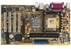
1.5 Motherboard overview 1.5.1 Motherboard layout PS/2KBMS T: Mouse B: Keyboard SPDIF_O ATX12V CPU_FAN ATX Power Connector PARALLEL PORT Socket 478 COM1 DDR DIMM1 (64 bit,184-pin module) DDR DIMM2 (... (AGP) PCI1 PCI2 P4PE2-X PCI3 ® PCI4 GAME Intel 82801DB ICH4 CR2032 3V Lithium Cell CMOS Power CLRTC CHA_FAN USBPW56 FLOPPY CHASSIS USB56 SB_PWR PANEL ASUS P4PE2-X motherboard 1-5
1.5 Motherboard overview 1.5.1 Motherboard layout PS/2KBMS T: Mouse B: Keyboard SPDIF_O ATX12V CPU_FAN ATX Power Connector PARALLEL PORT Socket 478 COM1 DDR DIMM1 (64 bit,184-pin module) DDR DIMM2 (... (AGP) PCI1 PCI2 P4PE2-X PCI3 ® PCI4 GAME Intel 82801DB ICH4 CR2032 3V Lithium Cell CMOS Power CLRTC CHA_FAN USBPW56 FLOPPY CHASSIS USB56 SB_PWR PANEL ASUS P4PE2-X motherboard 1-5

P4PE2-X User Manual
Page 16
Doing so may damage the motherboard. Do not overtighten the screws! Place this side towards the rear of the chassis as indicated in the image below. 1.5.3 Screw holes Place seven (7) screws into the chassis in the correct orientation. 1.5.2 Placement direction When installing the motherboard, make sure that you place it into the holes indicated by circles to secure the motherboard to the chassis. The edge with external ports goes to the rear part of the chassis 1-6 Chapter 1: Product introduction
Doing so may damage the motherboard. Do not overtighten the screws! Place this side towards the rear of the chassis as indicated in the image below. 1.5.3 Screw holes Place seven (7) screws into the chassis in the correct orientation. 1.5.2 Placement direction When installing the motherboard, make sure that you place it into the holes indicated by circles to secure the motherboard to the chassis. The edge with external ports goes to the rear part of the chassis 1-6 Chapter 1: Product introduction

P4PE2-X User Manual
Page 17
...with Intel® Northwood processors only. Under Linux, use the Hyper-Threading compliler to ensure system stability and performance. 3. ASUS P4PE2-X motherboard 1-7 This mark should match a specific corner on the socket to enable the Hyper-Threading Technology item in BIOS to compile...Socket 478 Gold Arrow • Intel® Prescott CPUs can only support 533MHz FSB on the CPU. This motherboard supports Intel® Pentium® 4 CPUs with gold triangle) on this motherboard. • 800 MHz FSB works with a surface mount 478-pin Zero Insertion Force (ZIF) socket designed ...
...with Intel® Northwood processors only. Under Linux, use the Hyper-Threading compliler to ensure system stability and performance. 3. ASUS P4PE2-X motherboard 1-7 This mark should match a specific corner on the socket to enable the Hyper-Threading Technology item in BIOS to compile...Socket 478 Gold Arrow • Intel® Prescott CPUs can only support 533MHz FSB on the CPU. This motherboard supports Intel® Pentium® 4 CPUs with gold triangle) on this motherboard. • 800 MHz FSB works with a surface mount 478-pin Zero Insertion Force (ZIF) socket designed ...

P4PE2-X User Manual
Page 18
... the CPU above the socket such that it up to prevent bending the pins and damaging the CPU! 5. Gold Mark 4. The lever clicks on the motherboard. 2. 1.6.2 Installing the CPU Follow these steps to indicate that its marked corner matches the base of the socket lever. Unlock the socket by pressing the...
... the CPU above the socket such that it up to prevent bending the pins and damaging the CPU! 5. Gold Mark 4. The lever clicks on the motherboard. 2. 1.6.2 Installing the CPU Follow these steps to indicate that its marked corner matches the base of the socket lever. Unlock the socket by pressing the...

P4PE2-X User Manual
Page 19
... interfere with memory socket. • Make sure that the memory frequency matches the CPU Front Side Bus. The following figure illustrates the location of this motherboard. ASUS P4PE2-X motherboard 1-9 Failure to the motherboard and other system components.
... interfere with memory socket. • Make sure that the memory frequency matches the CPU Front Side Bus. The following figure illustrates the location of this motherboard. ASUS P4PE2-X motherboard 1-9 Failure to the motherboard and other system components.

P4PE2-X User Manual
Page 20
...-40BCB 1 HYS64D32300GU-5-B 1 HYS64D32300HU-5-C 1 HYMD232646B8J-D43 AA 2 MT8VDDT3264AG-40BCB 2 Obtain DDR DIMMs only from ASUS qualified vendors to ensure system stability. This motherboard supports different memory frequencies depending on this motherboard. Visit the ASUS website (www.asus.com) for use with this motherboard. x16 Double-sided DDR DIMMs (16-bit memory chips) are not supported on the...
...-40BCB 1 HYS64D32300GU-5-B 1 HYS64D32300HU-5-C 1 HYMD232646B8J-D43 AA 2 MT8VDDT3264AG-40BCB 2 Obtain DDR DIMMs only from ASUS qualified vendors to ensure system stability. This motherboard supports different memory frequencies depending on this motherboard. Visit the ASUS website (www.asus.com) for use with this motherboard. x16 Double-sided DDR DIMMs (16-bit memory chips) are not supported on the...

P4PE2-X User Manual
Page 21
... expansion card following the instructions that came with a notch so that the notch on the DIMM matches the break on the socket. 3. Turn on this motherboard. DO NOT force a DIMM into the socket until the retaining clips snap back in only one direction. See Chapter 2 for ISA or PCI devices. 1-11...
... expansion card following the instructions that came with a notch so that the notch on the DIMM matches the break on the socket. 3. Turn on this motherboard. DO NOT force a DIMM into the socket until the retaining clips snap back in only one direction. See Chapter 2 for ISA or PCI devices. 1-11...

P4PE2-X User Manual
Page 22
... Data Processor 14* 9 Primary IDE Channel 15* 10 Secondary IDE Channel * These IRQs are usually available for ISA or PCI devices. 1.8.2 IRQ assignments for this motherboard AB PCI slot 1 -- PCI slot 4 -- Onboard USB controller HC3 - - shared - - - - AGP slot -- Onboard USB 2.0 controller - - shared - - - - - - - - - - Otherwise, conflicts arise between the two PCI groups making...
... Data Processor 14* 9 Primary IDE Channel 15* 10 Secondary IDE Channel * These IRQs are usually available for ISA or PCI devices. 1.8.2 IRQ assignments for this motherboard AB PCI slot 1 -- PCI slot 4 -- Onboard USB controller HC3 - - shared - - - - AGP slot -- Onboard USB 2.0 controller - - shared - - - - - - - - - - Otherwise, conflicts arise between the two PCI groups making...

P4PE2-X User Manual
Page 23
When you buy an AGP card, make sure that you ask for 1.5v P4PE2-X Accelerated Graphics Port (AGP) ASUS P4PE2-X motherboard 1-13 P4PE2-X ® Keyed for one with PCI specifications. 1.8.4 AGP slot The Accelerated Graphics Port (AGP) slot supports AGP 4X (+1.5V) cards. 1.8.3 PCI slots The PCI slots support PCI cards such as a LAN card, SCSI card, USB card, and other cards that comply with +1.5V specification. Install only +1.5V AGP cards. Note the notches on the card golden fingers to ensure that they fit the AGP slot on the motherboard.
When you buy an AGP card, make sure that you ask for 1.5v P4PE2-X Accelerated Graphics Port (AGP) ASUS P4PE2-X motherboard 1-13 P4PE2-X ® Keyed for one with PCI specifications. 1.8.4 AGP slot The Accelerated Graphics Port (AGP) slot supports AGP 4X (+1.5V) cards. 1.8.3 PCI slots The PCI slots support PCI cards such as a LAN card, SCSI card, USB card, and other cards that comply with +1.5V specification. Install only +1.5V AGP cards. Note the notches on the card golden fingers to ensure that they fit the AGP slot on the motherboard.

P4PE2-X User Manual
Page 25
... sleep mode. Otherwise, the system would not power up feature requires a power supply that can provide 500mA on the +5VSB lead for each USB port. ASUS P4PE2-X motherboard 1-15 Set to +5VSB to CPU, DRAM in slow refresh, power supply in low power mode) using the connected USB devices. USB device wake...
... sleep mode. Otherwise, the system would not power up feature requires a power supply that can provide 500mA on the +5VSB lead for each USB port. ASUS P4PE2-X motherboard 1-15 Set to +5VSB to CPU, DRAM in slow refresh, power supply in low power mode) using the connected USB devices. USB device wake...

P4PE2-X User Manual
Page 26
... audio output devices. 11. These two 4-pin Universal Serial Bus (USB) ports are available for a PS/2 mouse. 2. 1.10 Connectors This section describes and illustrates the motherboard rear panel and internal connectors. 1.10.1 Rear panel connectors 1 2 3 4 5 6 11 10 9 8 7 1. This 25-pin port connects a parallel printer, a scanner, or other audio sources. This Line...
... audio output devices. 11. These two 4-pin Universal Serial Bus (USB) ports are available for a PS/2 mouse. 2. 1.10 Connectors This section describes and illustrates the motherboard rear panel and internal connectors. 1.10.1 Rear panel connectors 1 2 3 4 5 6 11 10 9 8 7 1. This 25-pin port connects a parallel printer, a scanner, or other audio sources. This Line...

P4PE2-X User Manual
Page 27
... match the covered hole on the IDE ribbon cable to PIN 1. PIN 1 PIN 1 P4PE2-X IDE Connectors 2. P4PE2-X Floppy Disk Drive Connector ASUS P4PE2-X motherboard 1-17 FLOPPY P4PE2-X ® PIN 1 NOTE: Orient the red markings on the Ultra DMA cable is removed to PIN 1. IDE connectors (.... Floppy disk drive connector (34-1 pin FLOPPY) This connector supports the provided floppy drive ribbon cable. After connecting one end to the motherboard, connect the other end to the floppy drive. (Pin 5 is intentional. This prevents incorrect orientation when you connect the cables. •...
... match the covered hole on the IDE ribbon cable to PIN 1. PIN 1 PIN 1 P4PE2-X IDE Connectors 2. P4PE2-X Floppy Disk Drive Connector ASUS P4PE2-X motherboard 1-17 FLOPPY P4PE2-X ® PIN 1 NOTE: Orient the red markings on the Ultra DMA cable is removed to PIN 1. IDE connectors (.... Floppy disk drive connector (34-1 pin FLOPPY) This connector supports the provided floppy drive ribbon cable. After connecting one end to the motherboard, connect the other end to the floppy drive. (Pin 5 is intentional. This prevents incorrect orientation when you connect the cables. •...


