
P4PE2-X User Manual
Page 12
... surface mount ZIF socket. 1-2 Chapter 1: Product introduction Before you for buying the ASUS® P4PE2-X motherboard! The motherboard incorporates the Intel® Pentium® 4 Processor in your package with the Intel® 845PE chipset to set a new benchmark for the following items. ASUS P4PE2-X motherboard ASUS P4PE2-X series support CD 1 x 80-conductor Ultra DMA cable 1 x floppy drive signal cable...
... surface mount ZIF socket. 1-2 Chapter 1: Product introduction Before you for buying the ASUS® P4PE2-X motherboard! The motherboard incorporates the Intel® Pentium® 4 Processor in your package with the Intel® 845PE chipset to set a new benchmark for the following items. ASUS P4PE2-X motherboard ASUS P4PE2-X series support CD 1 x 80-conductor Ultra DMA cable 1 x floppy drive signal cable...

P4PE2-X User Manual
Page 13
...easily update the system BIOS even before loading the operating system. See page 2-6. ASUS P4PE2-X motherboard 1-3 DDR400 memory support Employing the Double Data Rate (DDR) memory technology, the P4PE2-X motherboard supports up to 2GB of system memory using unbuffered non-ECC PC3200*/2700/2100 ...12 for the CPU and DIMM requirements. *Overclocking mode Onboard LAN solution The motherboard has the Realtek® RTL8101L chipset onboard to buy a replacement ROM chip. USB 2.0 technology The motherboard implements the new Universal Serial Bus (USB) 2.0 specification, extending the connection ...
...easily update the system BIOS even before loading the operating system. See page 2-6. ASUS P4PE2-X motherboard 1-3 DDR400 memory support Employing the Double Data Rate (DDR) memory technology, the P4PE2-X motherboard supports up to 2GB of system memory using unbuffered non-ECC PC3200*/2700/2100 ...12 for the CPU and DIMM requirements. *Overclocking mode Onboard LAN solution The motherboard has the Realtek® RTL8101L chipset onboard to buy a replacement ROM chip. USB 2.0 technology The motherboard implements the new Universal Serial Bus (USB) 2.0 specification, extending the connection ...

P4PE2-X User Manual
Page 15
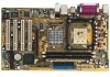
1.5 Motherboard overview 1.5.1 Motherboard layout PS/2KBMS T: Mouse B: Keyboard SPDIF_O ATX12V CPU_FAN ATX Power Connector PARALLEL PORT Socket 478 COM1 DDR DIMM1 (64 bit,184-pin module) DDR DIMM2 (...:Line Out Below:Mic In CD AUX FP_AUDIO AD1888 RTL 8101L Super I/O 3Mbit BIOS Intel 82845PE MCH SEC_IDE PRI_IDE Accelerated Graphics Port (AGP) PCI1 PCI2 P4PE2-X PCI3 ® PCI4 GAME Intel 82801DB ICH4 CR2032 3V Lithium Cell CMOS Power CLRTC CHA_FAN USBPW56 FLOPPY CHASSIS USB56 SB_PWR PANEL ASUS P4PE2-X motherboard 1-5
1.5 Motherboard overview 1.5.1 Motherboard layout PS/2KBMS T: Mouse B: Keyboard SPDIF_O ATX12V CPU_FAN ATX Power Connector PARALLEL PORT Socket 478 COM1 DDR DIMM1 (64 bit,184-pin module) DDR DIMM2 (...:Line Out Below:Mic In CD AUX FP_AUDIO AD1888 RTL 8101L Super I/O 3Mbit BIOS Intel 82845PE MCH SEC_IDE PRI_IDE Accelerated Graphics Port (AGP) PCI1 PCI2 P4PE2-X PCI3 ® PCI4 GAME Intel 82801DB ICH4 CR2032 3V Lithium Cell CMOS Power CLRTC CHA_FAN USBPW56 FLOPPY CHASSIS USB56 SB_PWR PANEL ASUS P4PE2-X motherboard 1-5

P4PE2-X User Manual
Page 17
... the CPU into the socket may bend the pins and severely damage the CPU! For more information on this motherboard. • 800 MHz FSB works with gold triangle) on the CPU. P4PE2-X ® P4PE2-X Socket 478 Gold Arrow • Intel® Prescott CPUs can only support 533MHz FSB on Hyper-Threading Technology, visit... the Hyper-Threading compliler to enable the Hyper-Threading Technology item in BIOS to ensure correct installation. If you install Windows® XP Service Pack 1. 4. ASUS P4PE2-X motherboard 1-7
... the CPU into the socket may bend the pins and severely damage the CPU! For more information on this motherboard. • 800 MHz FSB works with gold triangle) on the CPU. P4PE2-X ® P4PE2-X Socket 478 Gold Arrow • Intel® Prescott CPUs can only support 533MHz FSB on Hyper-Threading Technology, visit... the Hyper-Threading compliler to enable the Hyper-Threading Technology item in BIOS to ensure correct installation. If you install Windows® XP Service Pack 1. 4. ASUS P4PE2-X motherboard 1-7

P4PE2-X User Manual
Page 19
P4PE2-X ® P4PE2-X 184-Pin DDR DIMM Sockets • Make sure to unplug the power supply before adding or removing DIMMs or ...using a CPU with 64MB, 128MB, 256MB, 512MB, and 1GB densities into the DIMM sockets of the DDR DIMM sockets. Refer to the motherboard and other system components. DIMM1 DIMM2 80 Pins 104 Pins 1.7 System memory 1.7.1 DIMM sockets location You can only use one DDR 400 ... with 800 MHz FSB, you can install 64MB, 256MB, 512MB, and 1GB DDR DIMMs into the DIMM sockets. ASUS P4PE2-X motherboard 1-9 The following figure illustrates the location of this...
P4PE2-X ® P4PE2-X 184-Pin DDR DIMM Sockets • Make sure to unplug the power supply before adding or removing DIMMs or ...using a CPU with 64MB, 128MB, 256MB, 512MB, and 1GB densities into the DIMM sockets of the DDR DIMM sockets. Refer to the motherboard and other system components. DIMM1 DIMM2 80 Pins 104 Pins 1.7 System memory 1.7.1 DIMM sockets location You can only use one DDR 400 ... with 800 MHz FSB, you can install 64MB, 256MB, 512MB, and 1GB DDR DIMMs into the DIMM sockets. ASUS P4PE2-X motherboard 1-9 The following figure illustrates the location of this...

P4PE2-X User Manual
Page 23
Install only +1.5V AGP cards. Note the notches on the card golden fingers to ensure that they fit the AGP slot on the motherboard. P4PE2-X ® Keyed for one with PCI specifications. 1.8.4 AGP slot The Accelerated Graphics Port (AGP) slot supports AGP 4X (+1.5V) cards. When you buy an AGP card, make sure that you ask for 1.5v P4PE2-X Accelerated Graphics Port (AGP) ASUS P4PE2-X motherboard 1-13 1.8.3 PCI slots The PCI slots support PCI cards such as a LAN card, SCSI card, USB card, and other cards that comply with +1.5V specification.
Install only +1.5V AGP cards. Note the notches on the card golden fingers to ensure that they fit the AGP slot on the motherboard. P4PE2-X ® Keyed for one with PCI specifications. 1.8.4 AGP slot The Accelerated Graphics Port (AGP) slot supports AGP 4X (+1.5V) cards. When you buy an AGP card, make sure that you ask for 1.5v P4PE2-X Accelerated Graphics Port (AGP) ASUS P4PE2-X motherboard 1-13 1.8.3 PCI slots The PCI slots support PCI cards such as a LAN card, SCSI card, USB card, and other cards that comply with +1.5V specification.

P4PE2-X User Manual
Page 25
... under normal condition or in low power mode) using the connected USB devices. USBPW34 USBPW12 12 23 +5V (Default) +5VSB USBPW56 12 23 P4PE2-X ® +5V (Default) +5VSB P4PE2-X USB Device Wake Up • The USB device wake-up from S1 sleep mode (CPU stopped, DRAM refreshed, system running in sleep mode... provide 500mA on the +5VSB lead for each USB port. Set to +5VSB to CPU, DRAM in slow refresh, power supply in reduced power mode). ASUS P4PE2-X motherboard 1-15
... under normal condition or in low power mode) using the connected USB devices. USBPW34 USBPW12 12 23 +5V (Default) +5VSB USBPW56 12 23 P4PE2-X ® +5V (Default) +5VSB P4PE2-X USB Device Wake Up • The USB device wake-up from S1 sleep mode (CPU stopped, DRAM refreshed, system running in sleep mode... provide 500mA on the +5VSB lead for each USB port. Set to +5VSB to CPU, DRAM in slow refresh, power supply in reduced power mode). ASUS P4PE2-X motherboard 1-15

P4PE2-X User Manual
Page 27
...: Orient the red markings (usually zigzag) on the floppy ribbon cable to PIN 1. After connecting one end to the motherboard, connect the other end to the floppy drive. (Pin 5 is intentional. PIN 1 PIN 1 P4PE2-X IDE Connectors 2. This prevents incorrect orientation when you connect the cables. • The hole near the blue connector.... • Pin 20 on the Ultra DMA cable connector. Floppy disk drive connector (34-1 pin FLOPPY) This connector supports the provided floppy drive ribbon cable. P4PE2-X Floppy Disk Drive Connector ASUS P4PE2-X motherboard 1-17
...: Orient the red markings (usually zigzag) on the floppy ribbon cable to PIN 1. After connecting one end to the motherboard, connect the other end to the floppy drive. (Pin 5 is intentional. PIN 1 PIN 1 P4PE2-X IDE Connectors 2. This prevents incorrect orientation when you connect the cables. • The hole near the blue connector.... • Pin 20 on the Ultra DMA cable connector. Floppy disk drive connector (34-1 pin FLOPPY) This connector supports the provided floppy drive ribbon cable. P4PE2-X Floppy Disk Drive Connector ASUS P4PE2-X motherboard 1-17

P4PE2-X User Manual
Page 29
... fan connectors on the rear panel are not jumpers! The module has two USB 2.0 ports for additional USB ports. You may damage the motherboard components. These are inadequate, a USB header is purchased separately. • Install the USB 2.0 driver before using the USB 2.0 feature. ...at +12V. Lack of the connector. Rotation +12V GND Rotation +12V GND 5. DO NOT place jumper caps on the fan connectors! 6. ASUS P4PE2-X motherboard 1-19 CPU and chassis fan connectors (3-pin CPU_FAN, CHA_FAN) The fan connectors support cooling fans of 350mA~740mA (8.88W max.) or a ...
... fan connectors on the rear panel are not jumpers! The module has two USB 2.0 ports for additional USB ports. You may damage the motherboard components. These are inadequate, a USB header is purchased separately. • Install the USB 2.0 driver before using the USB 2.0 feature. ...at +12V. Lack of the connector. Rotation +12V GND Rotation +12V GND 5. DO NOT place jumper caps on the fan connectors! 6. ASUS P4PE2-X motherboard 1-19 CPU and chassis fan connectors (3-pin CPU_FAN, CHA_FAN) The fan connectors support cooling fans of 350mA~740mA (8.88W max.) or a ...

P4PE2-X User Manual
Page 31
...J2CX MIDI_OUT J2CY J2B2 MIDI_IN +5V J1B1 J1CX GND GND J1CY J1B2 +5V P4PE2-X ® GAME P4PE2-X Game Connector The GAME/MIDI module is purchased separately. 10. PWR Ground Reset Ground Reset SW... P4PE2-X IDE_LED ATX Power ® Switch* * Requires an ATX power supply. P4PE2-X System Panel Connector • System Power LED Lead (Green 3-1 pin PLED) This 3-1 pin...+ IDE_LED- GAME/MIDI connector (16-1 pin GAME) This connector supports a GAME/MIDI module. ASUS P4PE2-X motherboard 1-21
...J2CX MIDI_OUT J2CY J2B2 MIDI_IN +5V J1B1 J1CX GND GND J1CY J1B2 +5V P4PE2-X ® GAME P4PE2-X Game Connector The GAME/MIDI module is purchased separately. 10. PWR Ground Reset Ground Reset SW... P4PE2-X IDE_LED ATX Power ® Switch* * Requires an ATX power supply. P4PE2-X System Panel Connector • System Power LED Lead (Green 3-1 pin PLED) This 3-1 pin...+ IDE_LED- GAME/MIDI connector (16-1 pin GAME) This connector supports a GAME/MIDI module. ASUS P4PE2-X motherboard 1-21

P4PE2-X User Manual
Page 33
BIOS information ASUS P4PE2-X motherboard 2-1 Detailed descriptions of the BIOS parameters are also provided. Chapter 2 This chapter tells how to change system settings through the BIOS Setup menus.
BIOS information ASUS P4PE2-X motherboard 2-1 Detailed descriptions of the BIOS parameters are also provided. Chapter 2 This chapter tells how to change system settings through the BIOS Setup menus.

P4PE2-X User Manual
Page 35
... the update process. Doing so may not be exactly the same as shown. Visit the ASUS website (www.asus.com) to the bootable floppy disk that you see on your motherboard. What you copied to a bootable floppy disk. ASUS P4PE2-X motherboard 2-3 Write the BIOS file name on the screen is for your screen may cause system...
... the update process. Doing so may not be exactly the same as shown. Visit the ASUS website (www.asus.com) to the bootable floppy disk that you see on your motherboard. What you copied to a bootable floppy disk. ASUS P4PE2-X motherboard 2-3 Write the BIOS file name on the screen is for your screen may cause system...

P4PE2-X User Manual
Page 37
...drive, the error message "Floppy not found !" Visit the ASUS website (www.asus.com) to the floppy disk. Starting BIOS recovery... Checking for your motherboard and rename the downloaded file as "P4PE2-X.ROM". 4. Make sure to a floppy disk. 2. ASUS P4PE2-X motherboard 2-5 Reading flash ..... appears. • If the correct BIOS... Flash to update the BIOS The ASUS EZ Flash feature allows you to easily update the BIOS without having to display the following. Save the BIOS file to rename the downloaded BIOS file as P4PE2-X.ROM. User recovery requested. To launch EZ Flash, press ...
...drive, the error message "Floppy not found !" Visit the ASUS website (www.asus.com) to the floppy disk. Starting BIOS recovery... Checking for your motherboard and rename the downloaded file as "P4PE2-X.ROM". 4. Make sure to a floppy disk. 2. ASUS P4PE2-X motherboard 2-5 Reading flash ..... appears. • If the correct BIOS... Flash to update the BIOS The ASUS EZ Flash feature allows you to easily update the BIOS without having to display the following. Save the BIOS file to rename the downloaded BIOS file as P4PE2-X.ROM. User recovery requested. To launch EZ Flash, press ...

P4PE2-X User Manual
Page 39
Floppy found ! Reading file "P4PE2-X.ROM". Bad BIOS checksum. Checking for this motherboard. Start flashing... DO NOT shut down or reset the system while updating the BIOS! Visit ASUS website (www.asus.com) to download the latest BIOS file. When the BIOS update ...process is detected, the following screen message appears. The support CD contains the a working BIOS for floppy... Reading file "P4PE2-X.ROM". ASUS P4PE2-X motherboard 2-7 Bad BIOS checksum. Checking for CD-ROM... Boot the system. 2. Starting BIOS recovery... Floppy not found ! Starting BIOS ...
Floppy found ! Reading file "P4PE2-X.ROM". Bad BIOS checksum. Checking for this motherboard. Start flashing... DO NOT shut down or reset the system while updating the BIOS! Visit ASUS website (www.asus.com) to download the latest BIOS file. When the BIOS update ...process is detected, the following screen message appears. The support CD contains the a working BIOS for floppy... Reading file "P4PE2-X.ROM". ASUS P4PE2-X motherboard 2-7 Bad BIOS checksum. Checking for CD-ROM... Boot the system. 2. Starting BIOS recovery... Floppy not found ! Starting BIOS ...

P4PE2-X User Manual
Page 41
Use [+] or [-] to another. Some of a menu screen are the navigation keys for that particular menu. ASUS P4PE2-X motherboard 2-9 2.2.1 BIOS menu screen Menu items Menu bar Configuration fields General help System Time System Date Legacy Diskette A Primary IDE Master Primary IDE Slave ... [11:51:19] [Thu 08/05/2003] [1.44M, 3.5 in the menu and change the settings. Use the navigation keys to select items in ] : [ST320413A] : [ASUS CD-S340] : [Not Detected] : [Not Detected] Use [ENTER], [TAB] or [SHIFT-TAB] to select a field. Sub-menu items Navigation keys 2.2.2 Menu bar The ...
Use [+] or [-] to another. Some of a menu screen are the navigation keys for that particular menu. ASUS P4PE2-X motherboard 2-9 2.2.1 BIOS menu screen Menu items Menu bar Configuration fields General help System Time System Date Legacy Diskette A Primary IDE Master Primary IDE Slave ... [11:51:19] [Thu 08/05/2003] [1.44M, 3.5 in the menu and change the settings. Use the navigation keys to select items in ] : [ST320413A] : [ASUS CD-S340] : [Not Detected] : [Not Detected] Use [ENTER], [TAB] or [SHIFT-TAB] to select a field. Sub-menu items Navigation keys 2.2.2 Menu bar The ...

P4PE2-X User Manual
Page 43
...-S340] : [Not Detected] : [Not Detected] 2.3.1 System Time [xx:xx:xxxx] Allows you to set the system date 2.3.3 Legacy Diskette A [1.44M, 3.5 in .] ASUS P4PE2-X motherboard 2-11 Refer to section "2.2.1 BIOS menu screen" for information on the menu screen items and how to set the system time 2.3.2 System Date [Day xx/...
...-S340] : [Not Detected] : [Not Detected] 2.3.1 System Time [xx:xx:xxxx] Allows you to set the system date 2.3.3 Legacy Diskette A [1.44M, 3.5 in .] ASUS P4PE2-X motherboard 2-11 Refer to section "2.2.1 BIOS menu screen" for information on the menu screen items and how to set the system time 2.3.2 System Date [Day xx/...

P4PE2-X User Manual
Page 45
... Size : 256MB AMI BIOS Displays the auto-detected BIOS information Processor Displays the auto-detected CPU specification System Memory Displays the auto-detected system memory ASUS P4PE2-X motherboard 2-13 Configuration options: [Auto] [0] [1] [2] [3] [4] DMA Mode [Auto] Selects the DMA mode.
... Size : 256MB AMI BIOS Displays the auto-detected BIOS information Processor Displays the auto-detected CPU specification System Memory Displays the auto-detected system memory ASUS P4PE2-X motherboard 2-13 Configuration options: [Auto] [0] [1] [2] [3] [4] DMA Mode [Auto] Selects the DMA mode.

P4PE2-X User Manual
Page 47
... are set the DRAM timing parameters through the DRAM sub-items. The following sub-items appear when this item is Disabled. Configuration options: [Disabled] [Enabled] ASUS P4PE2-X motherboard 2-15 Select an item then press to change the advanced chipset settings. Configure Advanced CPU settings Manufacturer: Intel(R) Brand String: Intel(R) Pentium(R) 4 CPU 1.73G Frequency...
... are set the DRAM timing parameters through the DRAM sub-items. The following sub-items appear when this item is Disabled. Configuration options: [Disabled] [Enabled] ASUS P4PE2-X motherboard 2-15 Select an item then press to change the advanced chipset settings. Configure Advanced CPU settings Manufacturer: Intel(R) Brand String: Intel(R) Pentium(R) 4 CPU 1.73G Frequency...

P4PE2-X User Manual
Page 49
... you to change the USB-related features. Select an item then press to display the configuration options. If no USB device is set to Enabled. ASUS P4PE2-X motherboard 2-17 This item appears only when the Onboard LAN item is detected, the item shows None. 2.4.4 Onboard Devices Configuration OnBoard AC'97 Audio Onboard LAN...
... you to change the USB-related features. Select an item then press to display the configuration options. If no USB device is set to Enabled. ASUS P4PE2-X motherboard 2-17 This item appears only when the Onboard LAN item is detected, the item shows None. 2.4.4 Onboard Devices Configuration OnBoard AC'97 Audio Onboard LAN...

P4PE2-X User Manual
Page 51
Advanced PCI/PnP Settings WARNING: Setting wrong values in the system. Configuration options: [No] [Yes] ASUS P4PE2-X motherboard 2-19 Plug And Play O/S PCI Latency Timer Allocate IRQ to PCI VGA PCI IDE BusMaster [No] [64] [Yes] [Enabled] IRQ3 IRQ4 IRQ5 IRQ7 IRQ9 IRQ10 ...
Advanced PCI/PnP Settings WARNING: Setting wrong values in the system. Configuration options: [No] [Yes] ASUS P4PE2-X motherboard 2-19 Plug And Play O/S PCI Latency Timer Allocate IRQ to PCI VGA PCI IDE BusMaster [No] [64] [Yes] [Enabled] IRQ3 IRQ4 IRQ5 IRQ7 IRQ9 IRQ10 ...


