User Guide
Page 14
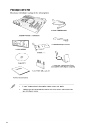
xiv Actual product specifications may vary with different models. Package contents Check your motherboard package for the following items ASUS X99-PRO/USB 3.1 motherboard 6 x Serial ATA 6 Gb/s cables 1 x ASUS Q-Shield 1 x ASUS SLI™ bridge connector HYPER M.2 x 4 Support DVD User Manual 1 x ASUS 2T2R dual-band Wi-Fi moving antennas (Wi-Fi 802.11a/b/g/n/ac compliant) 1 x 2-in-1 ASUS Q-Connector kit Technical documentations • If any of the above items is damaged or missing, contact your retailer. • The illustrated items above are for reference only.
xiv Actual product specifications may vary with different models. Package contents Check your motherboard package for the following items ASUS X99-PRO/USB 3.1 motherboard 6 x Serial ATA 6 Gb/s cables 1 x ASUS Q-Shield 1 x ASUS SLI™ bridge connector HYPER M.2 x 4 Support DVD User Manual 1 x ASUS 2T2R dual-band Wi-Fi moving antennas (Wi-Fi 802.11a/b/g/n/ac compliant) 1 x 2-in-1 ASUS Q-Connector kit Technical documentations • If any of the above items is damaged or missing, contact your retailer. • The illustrated items above are for reference only.
User Guide
Page 17
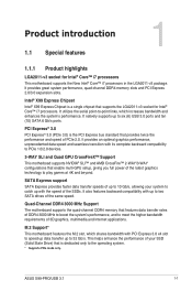
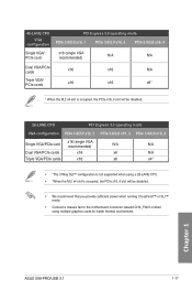
...) that enable multi-GPU setup, giving you full power of the same speed. This helps enhance the performance of PCIe 2.0. Chapter 1 ASUS X99-PRO/USB 3.1 1-1 SATA Express support SATA Express provides faster data transfer speeds of up to 32 Gb/s. It natively supports up to two SATA ...an optimal graphics performance, unprecedented data speed and seamless transition with up to play games at 4K and beyond. Intel® X99 Express Chipset Intel® X99 Express Chipset is dedicated only to PCIe 1.0/2.0 devices. 3-WAY SLI and Quad GPU CrossFireX™ Support This motherboad supports ...
...) that enable multi-GPU setup, giving you full power of the same speed. This helps enhance the performance of PCIe 2.0. Chapter 1 ASUS X99-PRO/USB 3.1 1-1 SATA Express support SATA Express provides faster data transfer speeds of up to 32 Gb/s. It natively supports up to two SATA ...an optimal graphics performance, unprecedented data speed and seamless transition with up to play games at 4K and beyond. Intel® X99 Express Chipset Intel® X99 Express Chipset is dedicated only to PCIe 1.0/2.0 devices. 3-WAY SLI and Quad GPU CrossFireX™ Support This motherboad supports ...

User Guide
Page 19
... antistatic pad or in the bag that the ATX power supply is switched off or the power cord is detached from the power supply. Chapter 1 ASUS X99-PRO/USB 3.1 1-3 1.2 Motherboard overview 1.2.1 Before you proceed Take note of the following precautions before you install motherboard components or change any motherboard settings. • Unplug the power...
... antistatic pad or in the bag that the ATX power supply is switched off or the power cord is detached from the power supply. Chapter 1 ASUS X99-PRO/USB 3.1 1-3 1.2 Motherboard overview 1.2.1 Before you proceed Take note of the following precautions before you install motherboard components or change any motherboard settings. • Unplug the power...
User Guide
Page 21
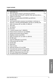
...Q-Code LEDs 20. Digital audio connector (4-1 pin SPDIF_OUT) 25. button 6. TPU switch 11. Front panel audio connector (10-1 pin AAFP) 24. USB 2.0 connectors (10-1 pin USB1112; TPM connector (20-1 pin TPM) 19. Serial port connector (10-1 pin COM) 23. CPU, CPU optional...1-22 1-33 1-21 1-40 1-41 1-38 1-39 1-35 1-20 1-24 1-39 1-28 1-19 1-19 1-41 1-42 1-33 1-25 1-40 Chapter 1 ASUS X99-PRO/USB 3.1 1-5 USB 3.0 connectors (20-1 pin USB3_12, USB3_34) 8. LGA2011-v3 CPU socket 4. Power-on button 22. DDR4 DIMM slots 2. Layout contents Connectors/Jumpers/Buttons and switches/Slots ...
...Q-Code LEDs 20. Digital audio connector (4-1 pin SPDIF_OUT) 25. button 6. TPU switch 11. Front panel audio connector (10-1 pin AAFP) 24. USB 2.0 connectors (10-1 pin USB1112; TPM connector (20-1 pin TPM) 19. Serial port connector (10-1 pin COM) 23. CPU, CPU optional...1-22 1-33 1-21 1-40 1-41 1-38 1-39 1-35 1-20 1-24 1-39 1-28 1-19 1-19 1-41 1-42 1-33 1-25 1-40 Chapter 1 ASUS X99-PRO/USB 3.1 1-5 USB 3.0 connectors (20-1 pin USB3_12, USB3_34) 8. LGA2011-v3 CPU socket 4. Power-on button 22. DDR4 DIMM slots 2. Layout contents Connectors/Jumpers/Buttons and switches/Slots ...

User Guide
Page 23
A DDR4 module is notched differently from a DDR, DDR2, or DDR3 module. DO NOT install a DDR, DDR2, or DDR3 memory module to the DDR4 slot. 1.2.4 System memory The motherboard comes with eight DDR 4 (Double Data Rate 4) Quad Inline Memory Modules (DIMM) slots. Recommended memory configurations Chapter 1 ASUS X99-PRO/USB 3.1 1-7
A DDR4 module is notched differently from a DDR, DDR2, or DDR3 module. DO NOT install a DDR, DDR2, or DDR3 memory module to the DDR4 slot. 1.2.4 System memory The motherboard comes with eight DDR 4 (Double Data Rate 4) Quad Inline Memory Modules (DIMM) slots. Recommended memory configurations Chapter 1 ASUS X99-PRO/USB 3.1 1-7

User Guide
Page 31
...into both the dark gray slots and black slots as three pairs of dual-channel memory configuration. or D.O.C.P. Load the X.M.P. Chapter 1 ASUS X99-PRO/USB 3.1 1-15 Single-sided DS - Supports two (2) modules inserted into any slot as fully-loaded quad-channel memory configurations. •...; ASUS exclusively provides hyper DIMM support function. • Hyper DIMM support is subject to the physical characteristics of quad-channel memory configuration. ...
...into both the dark gray slots and black slots as three pairs of dual-channel memory configuration. or D.O.C.P. Load the X.M.P. Chapter 1 ASUS X99-PRO/USB 3.1 1-15 Single-sided DS - Supports two (2) modules inserted into any slot as fully-loaded quad-channel memory configurations. •...; ASUS exclusively provides hyper DIMM support function. • Hyper DIMM support is subject to the physical characteristics of quad-channel memory configuration. ...
User Guide
Page 33
Chapter 1 ASUS X99-PRO/USB 3.1 1-17 40-LANE CPU VGA configuration Single VGA/ PCIe card PCI Express 3.0 operating mode PCIe 3.0/2.0 x16_1 PCIe 3.0/2.0 x16_3 PCIe 3.0/2.0 x16_4 x16 (single VGA recommended) N/A N/A Dual ...
Chapter 1 ASUS X99-PRO/USB 3.1 1-17 40-LANE CPU VGA configuration Single VGA/ PCIe card PCI Express 3.0 operating mode PCIe 3.0/2.0 x16_1 PCIe 3.0/2.0 x16_3 PCIe 3.0/2.0 x16_4 x16 (single VGA recommended) N/A N/A Dual ...

User Guide
Page 35
... the power cable before removing or installing any motherboard component. 2. Power-on button The motherboard comes with a power-on a bare or open-case system. Chapter 1 ASUS X99-PRO/USB 3.1 1-19 The button also lights up the system. 1.2.6 Onboard buttons and switches Onboard buttons and switches allow you to fine-tune performance when working on...
... the power cable before removing or installing any motherboard component. 2. Power-on button The motherboard comes with a power-on a bare or open-case system. Chapter 1 ASUS X99-PRO/USB 3.1 1-19 The button also lights up the system. 1.2.6 Onboard buttons and switches Onboard buttons and switches allow you to fine-tune performance when working on...

User Guide
Page 37
... and clock speed for a more enhanced performance. 4. Refer to section 1.2.8 Onboard LEDs for the exact location of the TPU LEDs. • If you have made. ASUS X99-PRO/USB 3.1 1-21 Chapter 1 • The TPU LEDs (TPU_LED) near the TPU switch light up when you to TPU_I mode or TPU_II mode. TPU switch With its...
... and clock speed for a more enhanced performance. 4. Refer to section 1.2.8 Onboard LEDs for the exact location of the TPU LEDs. • If you have made. ASUS X99-PRO/USB 3.1 1-21 Chapter 1 • The TPU LEDs (TPU_LED) near the TPU switch light up when you to TPU_I mode or TPU_II mode. TPU switch With its...

User Guide
Page 39
For the location of the EZ XMP LED, refer to enhance the DIMM's speed and performance. EZ XMP switch Enable this switch to overclock the installed DIMMs, allowing you enable the EZ XMP switch. The EZ XMP LED (XLED1) lights up when you to section 1.2.8 Onboard LEDs. 6. Chapter 1 ASUS X99-PRO/USB 3.1 1-23
For the location of the EZ XMP LED, refer to enhance the DIMM's speed and performance. EZ XMP switch Enable this switch to overclock the installed DIMMs, allowing you enable the EZ XMP switch. The EZ XMP LED (XLED1) lights up when you to section 1.2.8 Onboard LEDs. 6. Chapter 1 ASUS X99-PRO/USB 3.1 1-23

User Guide
Page 41
2. Chapter 1 ASUS X99-PRO/USB 3.1 1-25 To go back to its default CPU voltage setting, insert the jumper to set a higher CPU voltage for a flexible overclocking system, depending on the type of the installed CPU. CPU Over Voltage jumper (3-pin CPU_OV) The CPU Over Voltage jumper allows you to pins 1-2. To gain more CPU voltage setting, insert the jumper to pins 2-3.
2. Chapter 1 ASUS X99-PRO/USB 3.1 1-25 To go back to its default CPU voltage setting, insert the jumper to set a higher CPU voltage for a flexible overclocking system, depending on the type of the installed CPU. CPU Over Voltage jumper (3-pin CPU_OV) The CPU Over Voltage jumper allows you to pins 1-2. To gain more CPU voltage setting, insert the jumper to pins 2-3.

User Guide
Page 43
Chapter 1 ASUS X99-PRO/USB 3.1 1-27 EZ XMP LED (XLED1) This LED lights up when the EPU switch is enabled. 4. EPU LED (O2LED3) The EPU LED lights up when you enable the EZ XMP switch. 3.
Chapter 1 ASUS X99-PRO/USB 3.1 1-27 EZ XMP LED (XLED1) This LED lights up when the EPU switch is enabled. 4. EPU LED (O2LED3) The EPU LED lights up when you enable the EZ XMP switch. 3.
User Guide
Page 45
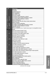
... (BDS) phase is started Driver connecting is started PCI Bus initialization is started PCI Bus Hot Plug Controller Initialization (continued on the next page) Chapter 1 ASUS X99-PRO/USB 3.1 1-29 Invalid memory type or incompatible memory speed Recovery firmware image is found Recovery firmware image is loaded Reserved for future AMI progress codes Recovery...
... (BDS) phase is started Driver connecting is started PCI Bus initialization is started PCI Bus Hot Plug Controller Initialization (continued on the next page) Chapter 1 ASUS X99-PRO/USB 3.1 1-29 Invalid memory type or incompatible memory speed Recovery firmware image is found Recovery firmware image is loaded Reserved for future AMI progress codes Recovery...

User Guide
Page 47
System has transitioned into ACPI mode. Chapter 1 ASUS X99-PRO/USB 3.1 1-31 Code D6 D7 D8 D9 DA DB DC Description No Console Output Devices are found No Console Input Devices are found Invalid password Error ...
System has transitioned into ACPI mode. Chapter 1 ASUS X99-PRO/USB 3.1 1-31 Code D6 D7 D8 D9 DA DB DC Description No Console Output Devices are found No Console Input Devices are found Invalid password Error ...

User Guide
Page 49
2. The S/PDIF module is for an additional Sony/Philips Digital Interface (S/PDIF) port. ASUS X99-PRO/USB 3.1 1-33 Connect the S/PDIF Out module cable to this connector, then install the module to install an M.2 (NGFF) SSD module. Chapter 1 This socket supports M Key and type 2242/2260/2280/22110 storage devices. M.2 socket 3 This socket allows you to a slot opening at the back of the system chassis. Digital audio connector (4-1 pin SPDIF_OUT) This connector is purchased separately. 3.
2. The S/PDIF module is for an additional Sony/Philips Digital Interface (S/PDIF) port. ASUS X99-PRO/USB 3.1 1-33 Connect the S/PDIF Out module cable to this connector, then install the module to install an M.2 (NGFF) SSD module. Chapter 1 This socket supports M Key and type 2242/2260/2280/22110 storage devices. M.2 socket 3 This socket allows you to a slot opening at the back of the system chassis. Digital audio connector (4-1 pin SPDIF_OUT) This connector is purchased separately. 3.

User Guide
Page 51
... connectors are for USB 2.0 ports. 5. These USB connectors comply with USB 2.0 specification that supports up to the USB connectors. The USB 2.0 module is purchased separately. ASUS X99-PRO/USB 3.1 1-35 Chapter 1 Doing so will damage the motherboard! DO NOT connect a 1394 cable to 48 Mb/s connection speed. You can connect the front panel USB cable to the ASUS Q-Connector (USB) first, and...
... connectors are for USB 2.0 ports. 5. These USB connectors comply with USB 2.0 specification that supports up to the USB connectors. The USB 2.0 module is purchased separately. ASUS X99-PRO/USB 3.1 1-35 Chapter 1 Doing so will damage the motherboard! DO NOT connect a 1394 cable to 48 Mb/s connection speed. You can connect the front panel USB cable to the ASUS Q-Connector (USB) first, and...

User Guide
Page 53
... 12 V Specification 2.0 (or later version) and provides a minimum power of 350 W. • DO NOT forget to the Recommended Power Supply Wattage Calculator at http://support.asus. ASUS X99-PRO/USB 3.1 1-37 Chapter 1
... 12 V Specification 2.0 (or later version) and provides a minimum power of 350 W. • DO NOT forget to the Recommended Power Supply Wattage Calculator at http://support.asus. ASUS X99-PRO/USB 3.1 1-37 Chapter 1

User Guide
Page 55
9. Connect the button cable that supports the DirectKey function. ASUS X99-PRO/USB 3.1 1-39 Chapter 1 A TPM system also helps enhance network security, protect digital identities, and ensures platform integrity. Ensure that supports the DirectKey feature. Refer to the ...
9. Connect the button cable that supports the DirectKey function. ASUS X99-PRO/USB 3.1 1-39 Chapter 1 A TPM system also helps enhance network security, protect digital identities, and ensures platform integrity. Ensure that supports the DirectKey feature. Refer to the ...

User Guide
Page 57
.... 14. A message appears when you connect the sensor or switch at the back of the chassis intrusion sensor or switch cable to this connector. Chapter 1 ASUS X99-PRO/USB 3.1 1-41 By default, the pin labeled "Chassis Signal" and "Ground" are for a chassis-mounted intrusion detection sensor or switch. Connect the serial port module cable...
.... 14. A message appears when you connect the sensor or switch at the back of the chassis intrusion sensor or switch cable to this connector. Chapter 1 ASUS X99-PRO/USB 3.1 1-41 By default, the pin labeled "Chassis Signal" and "Ground" are for a chassis-mounted intrusion detection sensor or switch. Connect the serial port module cable...

User Guide
Page 59
The motherboard layout may vary with models, but the installation steps are the same for reference only. ASUS X99-PRO/USB 3.1 2-1 Place the motherboard into the chassis, ensuring that its rear I/O ports are aligned to the chassis rear I /O panel. Install the ASUS Q-Shield to the chassis' rear I /O panel. 2. Chapter 2: Basic installation Basic installation 2.1 Building your PC system 2 2.1.1 Motherboard installation The diagrams in this section are for all models. 1.
The motherboard layout may vary with models, but the installation steps are the same for reference only. ASUS X99-PRO/USB 3.1 2-1 Place the motherboard into the chassis, ensuring that its rear I/O ports are aligned to the chassis rear I /O panel. Install the ASUS Q-Shield to the chassis' rear I /O panel. 2. Chapter 2: Basic installation Basic installation 2.1 Building your PC system 2 2.1.1 Motherboard installation The diagrams in this section are for all models. 1.


