User Manual
Page 6
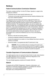
This equipment generates, uses and can be determined by turning the equipment off and on a circuit different from digital apparatus set out in a residential installation. The use of shielded cables for help. vi Changes or modifications to this equipment. WARNING! Canadian Department of the following two conditions: • This device may cause harmful interference to Part 15 of the FCC...
This equipment generates, uses and can be determined by turning the equipment off and on a circuit different from digital apparatus set out in a residential installation. The use of shielded cables for help. vi Changes or modifications to this equipment. WARNING! Canadian Department of the following two conditions: • This device may cause harmful interference to Part 15 of the FCC...
User Manual
Page 7
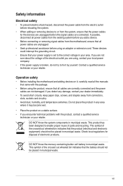
... it, carefully read all the manuals that came with the product, contact a qualified service technician or your area. Operation safety • Before installing the motherboard and adding devices on a stable surface. • If you encounter technical problems with the package. • Before using an adapter or extension cord. If you add a device. • Before connecting or removing signal cables from the motherboard, ensure that the product (electrical...
... it, carefully read all the manuals that came with the product, contact a qualified service technician or your area. Operation safety • Before installing the motherboard and adding devices on a stable surface. • If you encounter technical problems with the package. • Before using an adapter or extension cord. If you add a device. • Before connecting or removing signal cables from the motherboard, ensure that the product (electrical...
User Manual
Page 8
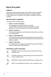
... motherboard layout, jumper settings, and connector locations. 4. IMPORTANT: Instructions that comes with hardware knowledge of the ASUS V-series P5G41E. Chapter 1: System introduction This chapter gives a general description of personal computers. CAUTION: Information to prevent damage to the components when trying to change system settings through the BIOS Setup menus and describes the BIOS parameters. viii The chapter lists the system features, including introduction on the front and rear panel...
... motherboard layout, jumper settings, and connector locations. 4. IMPORTANT: Instructions that comes with hardware knowledge of the ASUS V-series P5G41E. Chapter 1: System introduction This chapter gives a general description of personal computers. CAUTION: Information to prevent damage to the components when trying to change system settings through the BIOS Setup menus and describes the BIOS parameters. viii The chapter lists the system features, including introduction on the front and rear panel...
User Manual
Page 12
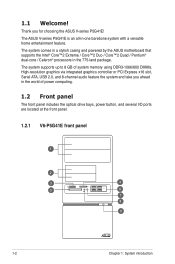
... graphics via integrated graphics controller or PCI Express x16 slot, Serial ATA, USB 2.0, and 8-channel audio feature the system and take you for choosing the ASUS V-series P5G41E! Thank you ahead in the world of power computing. 1.2 Front panel The front panel includes the optical drive bays, power button, and several I/O ports are located at the front panel. 1.2.1 V6-P5G41E front panel 1 2 3 4 5 6 7 8 9 R 1-2 Chapter 1: System introduction The system comes in a stylish casing and powered by the ASUS motherboard that supports...
... graphics via integrated graphics controller or PCI Express x16 slot, Serial ATA, USB 2.0, and 8-channel audio feature the system and take you for choosing the ASUS V-series P5G41E! Thank you ahead in the world of power computing. 1.2 Front panel The front panel includes the optical drive bays, power button, and several I/O ports are located at the front panel. 1.2.1 V6-P5G41E front panel 1 2 3 4 5 6 7 8 9 R 1-2 Chapter 1: System introduction The system comes in a stylish casing and powered by the ASUS motherboard that supports...
User Manual
Page 16
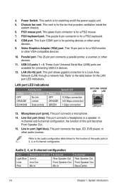
... connection to the audio configuration table below for a PS/2 mouse. 7. Microphone port (pink). COM port. USB 2.0 ports 1 ~ 4. These 4-pin Universal Serial Bus (USB) ports are available for switching on/off the power supply unit. 5. This port connects the tape, CD, DVD player, or other devices. 11. 4. This green 6-pin connector is for connecting USB 2.0 devices. 12. LAN (RJ-45) port. Refer to a Local Area Network (LAN) through a network hub. This port connects a microphone. 14. Line In port (light blue). Video Graphics Adapter (VGA) port. Power Switch. Chassis fan...
... connection to the audio configuration table below for a PS/2 mouse. 7. Microphone port (pink). COM port. USB 2.0 ports 1 ~ 4. These 4-pin Universal Serial Bus (USB) ports are available for switching on/off the power supply unit. 5. This port connects the tape, CD, DVD player, or other devices. 11. 4. This green 6-pin connector is for connecting USB 2.0 devices. 12. LAN (RJ-45) port. Refer to a Local Area Network (LAN) through a network hub. This port connects a microphone. 14. Line In port (light blue). Video Graphics Adapter (VGA) port. Power Switch. Chassis fan...
User Manual
Page 22
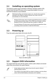
... necessary drivers. Use the setup procedures presented in a RAID set . • From the Windows XP setup screen, press F6 when prompted then follow succeeding screen instructions to install the SATA drivers. 2.2 Powering up Press the system power button ( ) to turn ON the system 2.3 Support DVD information The support DVD that came with the system contains useful software and several utility drivers that enhance the system features. • Screen display and driver options may not be the same for different operating...
... necessary drivers. Use the setup procedures presented in a RAID set . • From the Windows XP setup screen, press F6 when prompted then follow succeeding screen instructions to install the SATA drivers. 2.2 Powering up Press the system power button ( ) to turn ON the system 2.3 Support DVD information The support DVD that came with the system contains useful software and several utility drivers that enhance the system features. • Screen display and driver options may not be the same for different operating...

User Manual
Page 34
... 1.2.1 Motherboard layout for Express Gate appears. Eight seconds after you power on environment that gives you quick access to the Internet. When installing ASUS Express Gate on USB HDDs and flash drives, connect the drives to continue. 2-14 Chapter 2: Starting up The InstallShield Wizard for the exact location of the onboard SATA ports. • Ensure that your computer. 2. Select your computer: 1. Place the Support DVD into the optical drive. To install Express...
... 1.2.1 Motherboard layout for Express Gate appears. Eight seconds after you power on environment that gives you quick access to the Internet. When installing ASUS Express Gate on USB HDDs and flash drives, connect the drives to continue. 2-14 Chapter 2: Starting up The InstallShield Wizard for the exact location of the onboard SATA ports. • Ensure that your computer. 2. Select your computer: 1. Place the Support DVD into the optical drive. To install Express...
User Manual
Page 38
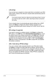
... is running (e.g. move the cable from a DHCP server, skip this step. • WiFi settings (if supported) If you plug the network cable into a different port while Express Gate is connected to your DSL/ cable modem, enable all the LAN ports. Express Gate automatically uses the connected port. When PPPoE is enabled on the wireless access point, select the corresponding security algorithm from a DHCP server, click Setup to configure the static IP settings manually. • LAN settings If you use a network cable connected...
... is running (e.g. move the cable from a DHCP server, skip this step. • WiFi settings (if supported) If you plug the network cable into a different port while Express Gate is connected to your DSL/ cable modem, enable all the LAN ports. Express Gate automatically uses the connected port. When PPPoE is enabled on the wireless access point, select the corresponding security algorithm from a DHCP server, click Setup to configure the static IP settings manually. • LAN settings If you use a network cable connected...
User Manual
Page 39
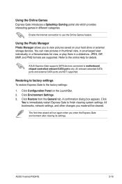
... list view, or play them in different categories. Click Configuration Panel on your hard drive or external storage devices. Click Yes to immediately restart Express Gate to motherboard . ASUS V-series P5G41E 2-19 JPEG, GIF, BMP, and PNG formats are NOT supported. A confirmation dialog box appears. Refer to use the Online Games feature. All bookmarks, network settings, and other changes you enter the Express Gate environment after clearing its settings...
... list view, or play them in different categories. Click Configuration Panel on your hard drive or external storage devices. Click Yes to immediately restart Express Gate to motherboard . ASUS V-series P5G41E 2-19 JPEG, GIF, BMP, and PNG formats are NOT supported. A confirmation dialog box appears. Refer to use the Online Games feature. All bookmarks, network settings, and other changes you enter the Express Gate environment after clearing its settings...
User Manual
Page 40
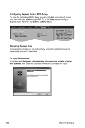
... Power ASUS EZ Flash 2 Express Gate Enter OS Timer Reset User Data BIOS SETUP UTILITY Boot Tools Exit [Auto] [10 Seconds] [No] Press ENTER to run the utility to 4.7.2 Express Gate for details. Refer to select and update BIOS. This utility supports 1.FAT 12/16/32 (r/w) 2.NTFS (read only) 3.CD-DISC (read only) Repairing Express Gate In case Express Gate does not start normally, reinstall the software or use the repair utility to complete the repair...
... Power ASUS EZ Flash 2 Express Gate Enter OS Timer Reset User Data BIOS SETUP UTILITY Boot Tools Exit [Auto] [10 Seconds] [No] Press ENTER to run the utility to 4.7.2 Express Gate for details. Refer to select and update BIOS. This utility supports 1.FAT 12/16/32 (r/w) 2.NTFS (read only) 3.CD-DISC (read only) Repairing Express Gate In case Express Gate does not start normally, reinstall the software or use the repair utility to complete the repair...
User Manual
Page 43
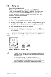
... pins 1-2 (default) to overclocking, use the CPU Parameter Recall (C.P.R.) feature. ASUS V-series P5G41E 3-3 Clear RTC RAM (3-pin CLRTC) This jumper allows you to overclocking. Shut down the key during the boot process and enter BIOS setup to clear the CMOS RTC RAM data. For system failure due to pins 2-3. Except when clearing the RTC RAM, never remove the cap on pins 2-3 for about 5-10 seconds, then move the jumper again to re-enter data. Plug the power cord and turn...
... pins 1-2 (default) to overclocking, use the CPU Parameter Recall (C.P.R.) feature. ASUS V-series P5G41E 3-3 Clear RTC RAM (3-pin CLRTC) This jumper allows you to overclocking. Shut down the key during the boot process and enter BIOS setup to clear the CMOS RTC RAM data. For system failure due to pins 2-3. Except when clearing the RTC RAM, never remove the cap on pins 2-3 for about 5-10 seconds, then move the jumper again to re-enter data. Plug the power cord and turn...
User Manual
Page 52
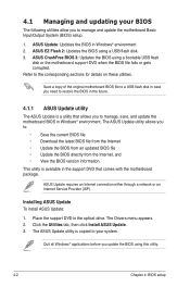
...network or an Internet Service Provider (ISP). Quit all Windows® applications before you to manage and update the motherboard Basic Input/Output System (BIOS) setup. 1. Refer to your BIOS The following utilities allow you update the BIOS using this utility. 4-2 Chapter 4: BIOS setup Installing ASUS Update To install ASUS Update: 1. This utility is available in the support DVD that allows you to restore the BIOS in Windows® environment. The Drivers menu appears. 2. Click the Utilities tab, then click Install ASUS Update. 3. ASUS EZ Flash 2: Updates the BIOS using...
...network or an Internet Service Provider (ISP). Quit all Windows® applications before you to manage and update the motherboard Basic Input/Output System (BIOS) setup. 1. Refer to your BIOS The following utilities allow you update the BIOS using this utility. 4-2 Chapter 4: BIOS setup Installing ASUS Update To install ASUS Update: 1. This utility is available in the support DVD that allows you to restore the BIOS in Windows® environment. The Drivers menu appears. 2. Click the Utilities tab, then click Install ASUS Update. 3. ASUS EZ Flash 2: Updates the BIOS using...

User Manual
Page 55
... it . You can support devices such as USB flash disk with FAT 32/16 format and single partition only. • Do not shut down or reset the system while updating the BIOS to download the latest BIOS file for the motherboard. 2. 4.1.2 ASUS EZ Flash 2 utility The ASUS EZ Flash 2 feature allows you to update the BIOS without having to go through the long process of booting from a floppy disk and using EZ Flash 2: 1.
... it . You can support devices such as USB flash disk with FAT 32/16 format and single partition only. • Do not shut down or reset the system while updating the BIOS to download the latest BIOS file for the motherboard. 2. 4.1.2 ASUS EZ Flash 2 utility The ASUS EZ Flash 2 feature allows you to update the BIOS without having to go through the long process of booting from a floppy disk and using EZ Flash 2: 1.
User Manual
Page 57
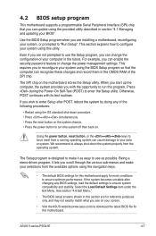
..., POST continues with the opportunity to run this motherboard apply for most conditions to download the latest BIOS file for this utility. ASUS V-series P5G41E 4-7 If you can change the power management settings. Using the power button, reset button, or the ++ keys to ensure system compatibility and stability. We recommend to your selections from the operating system. Select the Load Default Settings item under the Exit Menu. For example, you can cause...
..., POST continues with the opportunity to run this motherboard apply for most conditions to download the latest BIOS file for this utility. ASUS V-series P5G41E 4-7 If you can change the power management settings. Using the power button, reset button, or the ++ keys to ensure system compatibility and stability. We recommend to your selections from the operating system. Select the Load Default Settings item under the Exit Menu. For example, you can cause...
User Manual
Page 61
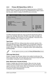
... Advanced BIOS SETUP UTILITY Power Boot Tools Exit Primary IDE Master Device : Not Detected Select the type of device connected to the system Type LBA/Large Mode Block(Multi-Sector Transfer) M PIO Mode DMA Mode SMART Monitoring 32Bit Data Transfer [Auto] [Auto] [Auto] [Auto] [Auto] [Auto] [Enabled] Select Screen Select Item Enter Go to Auto allows automatic selection of the appropriate IDE device type. These values are specifically configuring a CD-ROM drive. Configuration options: [Not Installed...
... Advanced BIOS SETUP UTILITY Power Boot Tools Exit Primary IDE Master Device : Not Detected Select the type of device connected to the system Type LBA/Large Mode Block(Multi-Sector Transfer) M PIO Mode DMA Mode SMART Monitoring 32Bit Data Transfer [Auto] [Auto] [Auto] [Auto] [Auto] [Auto] [Enabled] Select Screen Select Item Enter Go to Auto allows automatic selection of the appropriate IDE device type. These values are specifically configuring a CD-ROM drive. Configuration options: [Not Installed...
User Manual
Page 64
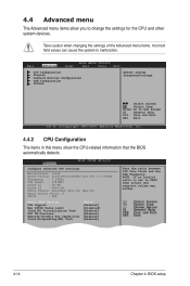
... Frequency. Take caution when changing the settings of the Advanced menu items. Incorrect field values can cause the system to change the settings for the CPU and other system devices. NOTE: If an invalid ratio is set in this menu show the CPU-related information that the BIOS automatically detects. Main Advanced BIOS SETUP UTILITY Power Boot Tools Exit CPU Configuration Chipset Onboard Devices Configuration USB Configuration PCIPnP Adjust system frequency/voltage...
... Frequency. Take caution when changing the settings of the Advanced menu items. Incorrect field values can cause the system to change the settings for the CPU and other system devices. NOTE: If an invalid ratio is set in this menu show the CPU-related information that the BIOS automatically detects. Main Advanced BIOS SETUP UTILITY Power Boot Tools Exit CPU Configuration Chipset Onboard Devices Configuration USB Configuration PCIPnP Adjust system frequency/voltage...
User Manual
Page 66
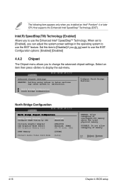
Set this item to [Disabled] if you to change the advanced chipset settings. Configuration options: [Enabled] [Disabled] 4.4.2 Chipset The Chipset menu allows you do not want to use the EIST. When set to [Enabled], you installed an Intel® Pentium® 4 or later CPU that supports the Enhanced Intel SpeedStep® Technology (EIST). Advanced Chipset Settings WARNING: Setting wrong values in the operating system to use the EIST feature. The...
Set this item to [Disabled] if you to change the advanced chipset settings. Configuration options: [Enabled] [Disabled] 4.4.2 Chipset The Chipset menu allows you do not want to use the EIST. When set to [Enabled], you installed an Intel® Pentium® 4 or later CPU that supports the Enhanced Intel SpeedStep® Technology (EIST). Advanced Chipset Settings WARNING: Setting wrong values in the operating system to use the EIST feature. The...
User Manual
Page 68
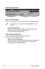
... Audio Controller item is used, set the audio controller. Front Panel Type [HD Audio] Allows you to enable or disable the onboard LAN controller. Configuration options: [Enabled] [Disabled] Onboard LAN Boot ROM [Disabled] Allows you to enable or disable the boot ROM in the onboard LAN controller. Configuration options: [Disabled] [Enabled] 4-18 Chapter 4: BIOS setup If High Definition Audio Front Panel is set to Enabled. South Bridge Configuration South Bridge chipset Configuration Audio Controller Front Panel Support Type Onboard Gigabit LAN Onboard LAN Boot ROM [Enabled...
... Audio Controller item is used, set the audio controller. Front Panel Type [HD Audio] Allows you to enable or disable the onboard LAN controller. Configuration options: [Enabled] [Disabled] Onboard LAN Boot ROM [Disabled] Allows you to enable or disable the boot ROM in the onboard LAN controller. Configuration options: [Disabled] [Enabled] 4-18 Chapter 4: BIOS setup If High Definition Audio Front Panel is set to Enabled. South Bridge Configuration South Bridge chipset Configuration Audio Controller Front Panel Support Type Onboard Gigabit LAN Onboard LAN Boot ROM [Enabled...
User Manual
Page 77
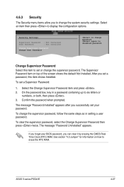
... display the configuration options. After you successfully set a Supervisor Password: 1. The message "Password Uninstalled" appears. Select Screen Select Item +- On the password box, key in setting a user password. If you forget your password. ASUS V-series P5G41E 4-27 Security Settings Supervisor Password : Not Installed User Password : Not Installed Change Supervisor Password Change User Passward to six letters or numbers, or both, then press . 3. 4.6.3 Security The Security menu items allow you can clear it by erasing the CMOS Real Time Clock (RTC) RAM...
... display the configuration options. After you successfully set a Supervisor Password: 1. The message "Password Uninstalled" appears. Select Screen Select Item +- On the password box, key in setting a user password. If you forget your password. ASUS V-series P5G41E 4-27 Security Settings Supervisor Password : Not Installed User Password : Not Installed Change Supervisor Password Change User Passward to six letters or numbers, or both, then press . 3. 4.6.3 Security The Security menu items allow you can clear it by erasing the CMOS Real Time Clock (RTC) RAM...
User Manual
Page 78
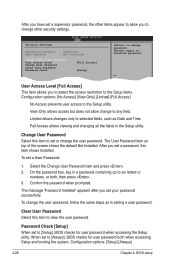
... to clear the user password. The User Password item on top of the screen shows the default Not Installed. Change Option User Access Level [Full Access] F1 General Help F10 Save and Exit This item allows you set your password successfully. Change User Password Select this item to set to [Setup], BIOS checks for user password both , then press . . 3. Configuration options: [Setup] [Always] 4-28 Chapter 4: BIOS setup Limited allows changes only to [Always], BIOS checks for user password when accessing the Setup utility. To set to...
... to clear the user password. The User Password item on top of the screen shows the default Not Installed. Change Option User Access Level [Full Access] F1 General Help F10 Save and Exit This item allows you set your password successfully. Change User Password Select this item to set to [Setup], BIOS checks for user password both , then press . . 3. Configuration options: [Setup] [Always] 4-28 Chapter 4: BIOS setup Limited allows changes only to [Always], BIOS checks for user password when accessing the Setup utility. To set to...


