

E732 MANUAL TERMINATOR K7 English V1.0
Page 5
Table of Contents Disclaimer/Copyrights 2 ASUS Contact Information 3 FCC/CDC Statements 4 System Package Contents 7 Introduction: About This Guide 9 Audience 10 Contents Description 10 Chapter 1: System Introduction 11 1.1...Install a Modem Riser Card 26 2.8 Install a PCI Expansion Card 27 2.9 Re-connect Cables 28 2.10 Replace the Cover 30 2.11 Connect External Devices 32 2.12 Power Supply Specifications 33 Chapter 3: M/B Information 35 3.1 Specifications 36 3.2 Components 38 3.3 Layout 40 3.4 Hardware Setup Procedures 41 3.5 Motherboard Settings 42 3.6 System Memory 45 3.7 ...
Table of Contents Disclaimer/Copyrights 2 ASUS Contact Information 3 FCC/CDC Statements 4 System Package Contents 7 Introduction: About This Guide 9 Audience 10 Contents Description 10 Chapter 1: System Introduction 11 1.1...Install a Modem Riser Card 26 2.8 Install a PCI Expansion Card 27 2.9 Re-connect Cables 28 2.10 Replace the Cover 30 2.11 Connect External Devices 32 2.12 Power Supply Specifications 33 Chapter 3: M/B Information 35 3.1 Specifications 36 3.2 Components 38 3.3 Layout 40 3.4 Hardware Setup Procedures 41 3.5 Motherboard Settings 42 3.6 System Memory 45 3.7 ...

E732 MANUAL TERMINATOR K7 English V1.0
Page 7
It saves you a lot of time not having to hunt down components when you are assembling the system by yourself, make sure to prepare all the components before starting. System Package Contents The following checklist enumerates the components included in the standard system package. 1) System Chassis 2) Motherboard 3) Switching Power Supply 4) 1.44MB Floppy Disk Drive 5) CD-ROM Drive (optional) 6) 56K PCI Modem Card (optional) 7) Support CD with Drivers and Utilities 8) Installation Guide NOTE If you need them. 7
It saves you a lot of time not having to hunt down components when you are assembling the system by yourself, make sure to prepare all the components before starting. System Package Contents The following checklist enumerates the components included in the standard system package. 1) System Chassis 2) Motherboard 3) Switching Power Supply 4) 1.44MB Floppy Disk Drive 5) CD-ROM Drive (optional) 6) 56K PCI Modem Card (optional) 7) Support CD with Drivers and Utilities 8) Installation Guide NOTE If you need them. 7

E732 MANUAL TERMINATOR K7 English V1.0
Page 12
... of the front panel is composed of the ASUS A7VC motherboard, a power supply, and a floppy disk drive in the above figure. 12 Chapter 1: System Introduction Push the dotted area of the door to open it and show the front panel features. 1.1 Front Panel Features The ASUS Terminator K7 barebone system is a door that covers accessible I/O features...
... of the front panel is composed of the ASUS A7VC motherboard, a power supply, and a floppy disk drive in the above figure. 12 Chapter 1: System Introduction Push the dotted area of the door to open it and show the front panel features. 1.1 Front Panel Features The ASUS Terminator K7 barebone system is a door that covers accessible I/O features...

E732 MANUAL TERMINATOR K7 English V1.0
Page 13
...with a voltage selector switch located below the power socket. Setting the switch to 115V. 1.2 Rear Panel Features The rear panel of the ASUS Terminator K7 barebone system includes the standard PC99 I/O connectors for external devices, power supply socket, and optional modem connectors. Game/MIDI ...RJ-45) USB Connectors (Ports 0&1) Modem (optional) Power Supply Voltage Selector The switching power supply is 200-240V, set the switch to 115V in your area. ASUS Terminator K7 Barebone System 13 If the AC voltage supply in a 230V environment will seriously damage the system. ...
...with a voltage selector switch located below the power socket. Setting the switch to 115V. 1.2 Rear Panel Features The rear panel of the ASUS Terminator K7 barebone system includes the standard PC99 I/O connectors for external devices, power supply socket, and optional modem connectors. Game/MIDI ...RJ-45) USB Connectors (Ports 0&1) Modem (optional) Power Supply Voltage Selector The switching power supply is 200-240V, set the switch to 115V in your area. ASUS Terminator K7 Barebone System 13 If the AC voltage supply in a 230V environment will seriously damage the system. ...

E732 MANUAL TERMINATOR K7 English V1.0
Page 14
Two 5.25" 3.5" HDD 3.5" Floppy Drive Bays Drive Bay Drive Motherboard USB/audio Board Power Supply 14 Chapter 1: System Introduction You will see here the standard components that come already installed in the system and the places where you remove the cover and flip out the drive frame. 1.3 Internal Features The figure below shows the internal view of the system when you can install the other required components to get the system running.
Two 5.25" 3.5" HDD 3.5" Floppy Drive Bays Drive Bay Drive Motherboard USB/audio Board Power Supply 14 Chapter 1: System Introduction You will see here the standard components that come already installed in the system and the places where you remove the cover and flip out the drive frame. 1.3 Internal Features The figure below shows the internal view of the system when you can install the other required components to get the system running.

E732 MANUAL TERMINATOR K7 English V1.0
Page 23
Connect the other end of the IDE ribbon cable to the power connector at the back of the IDE hard disk ribbon cable to Pin 1 Power Cable (HDD) 7. Connect a power cable from the power supply to the primary IDE connector (blue connector labeled IDE1) on the IDE Ribbon Cable IDE interface. Connect one end of the... with Pin 1 on the motherboard. 2.5 Install a Hard Disk Drive 5. Red Stripe to the IDE interface at the back of the HDD. Primary IDE Connector (IDE1) ASUS Terminator K7 Barebone System 23
Connect the other end of the IDE ribbon cable to the power connector at the back of the IDE hard disk ribbon cable to Pin 1 Power Cable (HDD) 7. Connect a power cable from the power supply to the primary IDE connector (blue connector labeled IDE1) on the IDE Ribbon Cable IDE interface. Connect one end of the... with Pin 1 on the motherboard. 2.5 Install a Hard Disk Drive 5. Red Stripe to the IDE interface at the back of the HDD. Primary IDE Connector (IDE1) ASUS Terminator K7 Barebone System 23

E732 MANUAL TERMINATOR K7 English V1.0
Page 25
... cable to the secondary IDE connector (black connector labeled IDE2) on the motherboard. 2.6 Install a CD-ROM Drive 5. Connect a power cable from the power supply to the power connector at the back of the audio cable to the IDE interface at the back of the CD-ROM. Connect the other end...ROM, matching the red stripe on the IDE interface. CD-ROM Connector (CD) Secondary IDE Connector (IDE2) ASUS Terminator K7 Barebone System 25 Connect one end of the CDROM audio cable to Pin 1 Power Cable (P6) 8. Use the cable with Pin 1 CD-ROM Audio Cable on the cable with the ...
... cable to the secondary IDE connector (black connector labeled IDE2) on the motherboard. 2.6 Install a CD-ROM Drive 5. Connect a power cable from the power supply to the power connector at the back of the audio cable to the IDE interface at the back of the CD-ROM. Connect the other end...ROM, matching the red stripe on the IDE interface. CD-ROM Connector (CD) Secondary IDE Connector (IDE2) ASUS Terminator K7 Barebone System 25 Connect one end of the CDROM audio cable to Pin 1 Power Cable (P6) 8. Use the cable with Pin 1 CD-ROM Audio Cable on the cable with the ...

E732 MANUAL TERMINATOR K7 English V1.0
Page 29
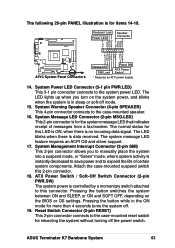
... Lock Power LED Speaker Connector Speaker Ground Ground +5V Ground Keylock PLED +5 V Ground Reset Ground PWR Ground ExtSMI# TB_LED +5 V USB1 Connector PANEL Connector IDELED Lead Pin 1 Message LED SMI Lead Reset SW ATX Power Switch* * Requires an ATX power supply. 2.9.2 Motherboard Connectors The figures below show the specific connectors on the Motherboard ASUS Terminator K7 Barebone System...
... Lock Power LED Speaker Connector Speaker Ground Ground +5V Ground Keylock PLED +5 V Ground Reset Ground PWR Ground ExtSMI# TB_LED +5 V USB1 Connector PANEL Connector IDELED Lead Pin 1 Message LED SMI Lead Reset SW ATX Power Switch* * Requires an ATX power supply. 2.9.2 Motherboard Connectors The figures below show the specific connectors on the Motherboard ASUS Terminator K7 Barebone System...

E732 MANUAL TERMINATOR K7 English V1.0
Page 33
By shorting +5Vsb, the power supply can latch down and latch off for shorting +5V, +12V, -12V, -5V, or +3.3V. ASUS Terminator K7 Barebone System 33 at 115Vac, full load cold start at nominal input, maximum load Output Characteristics Output Voltage +5V +12V -12V ...Output Voltage +5V +12V +3.3V Maximum Voltage 6.5V 15.6V 4.3V NOTE The power supply will shut down or automatically recover when the fault condition is removed. at 25°C Efficiency 70% min. 2.12 Power Supply Specifications Input Characteristics Input Voltage Range Min Nom Max Range 1 90V 115V 135V Range 2...
By shorting +5Vsb, the power supply can latch down and latch off for shorting +5V, +12V, -12V, -5V, or +3.3V. ASUS Terminator K7 Barebone System 33 at 115Vac, full load cold start at nominal input, maximum load Output Characteristics Output Voltage +5V +12V -12V ...Output Voltage +5V +12V +3.3V Maximum Voltage 6.5V 15.6V 4.3V NOTE The power supply will shut down or automatically recover when the fault condition is removed. at 25°C Efficiency 70% min. 2.12 Power Supply Specifications Input Characteristics Input Voltage Range Min Nom Max Range 1 90V 115V 135V Range 2...

E732 MANUAL TERMINATOR K7 English V1.0
Page 38
.../Audio Board (refer to UAEX layout on p. 29) Line Out (LOUT) Connector Microphone (MIC) Connector LO2 Header MIC 2 Header 2 USB Connectors (Port 0 & Port 1) USB2P Header Power ATX Power Supply Connector 5 ATX 12V Connector 2 Form Factor FlexATX 38 Chapter 3: Motherboard Information
.../Audio Board (refer to UAEX layout on p. 29) Line Out (LOUT) Connector Microphone (MIC) Connector LO2 Header MIC 2 Header 2 USB Connectors (Port 0 & Port 1) USB2P Header Power ATX Power Supply Connector 5 ATX 12V Connector 2 Form Factor FlexATX 38 Chapter 3: Motherboard Information

E732 MANUAL TERMINATOR K7 English V1.0
Page 41
... whenever the components are separated from static electricity, you should follow some precautions whenever you unplug the power supply when adding or removing system components. ASUS Terminator K7 Barebone System 41 Check motherboard settings 2. Install an expansion card 5. Setup the BIOS software WARNING! ...(CPU) 4. Computer motherboards and expansion cards contain very delicate Integrated Circuit (IC) chips. Ensure that the ATX power supply is in or remove the ATX power connector on the bag that you work on the inside. 2. WARNING! Failure to touch the IC chips, leads...
... whenever the components are separated from static electricity, you should follow some precautions whenever you unplug the power supply when adding or removing system components. ASUS Terminator K7 Barebone System 41 Check motherboard settings 2. Install an expansion card 5. Setup the BIOS software WARNING! ...(CPU) 4. Computer motherboards and expansion cards contain very delicate Integrated Circuit (IC) chips. Ensure that the ATX power supply is in or remove the ATX power connector on the bag that you work on the inside. 2. WARNING! Failure to touch the IC chips, leads...

E732 MANUAL TERMINATOR K7 English V1.0
Page 43
The FS jumper is set to [1-2]. system running in reduced power mode). RAM refreshed; power supply in low power mode) using the connected USB devices. Set these jumpers to +5V to CPU; If AMD 133 MHz capacity processors are used, then reset the jumper ... Ports). JP1A 12 23 A7VC +5V +5VSB (Back Panel USB Port) JP1B 12 23 ® A7VC USB Ports Setting +5V +5VSB (Front Panel USB Port) ASUS Terminator K7 Barebone System 43 2. The FS jumper settings should match the capacity of the processor. Otherwise, the motherboard may not boot up from S1 sleep state...
The FS jumper is set to [1-2]. system running in reduced power mode). RAM refreshed; power supply in low power mode) using the connected USB devices. Set these jumpers to +5V to CPU; If AMD 133 MHz capacity processors are used, then reset the jumper ... Ports). JP1A 12 23 A7VC +5V +5VSB (Back Panel USB Port) JP1B 12 23 ® A7VC USB Ports Setting +5V +5VSB (Front Panel USB Port) ASUS Terminator K7 Barebone System 43 2. The FS jumper settings should match the capacity of the processor. Otherwise, the motherboard may not boot up from S1 sleep state...

E732 MANUAL TERMINATOR K7 English V1.0
Page 46
Make sure that you unplug the power supply when adding or removing memory modules or other system components. Insert the module(s) into the DIMM slot on each side and have a higher pin density ...
Make sure that you unplug the power supply when adding or removing memory modules or other system components. Insert the module(s) into the DIMM slot on each side and have a higher pin density ...

E732 MANUAL TERMINATOR K7 English V1.0
Page 57
... sure that the ATX power supply can supply at least 720mA +5VSB. +5.0 Volts +5.0 Volts -5.0 Volts Ground Ground Ground Power Supply On Ground -12.0Volts +3.3Volts ATXPWR A7VC ATX12V COM COM +12V DC +12V DC ® A7VC ATX & Auxiliary Power Connectors +12.0Volts +5V Standby Power Good Ground +5.0 Volts Ground +5.0 Volts Ground +3.3 Volts +3.3 Volts ASUS Terminator K7 Barebone System 57 The...
... sure that the ATX power supply can supply at least 720mA +5VSB. +5.0 Volts +5.0 Volts -5.0 Volts Ground Ground Ground Power Supply On Ground -12.0Volts +3.3Volts ATXPWR A7VC ATX12V COM COM +12V DC +12V DC ® A7VC ATX & Auxiliary Power Connectors +12.0Volts +5V Standby Power Good Ground +5.0 Volts Ground +5.0 Volts Ground +3.3 Volts +3.3 Volts ASUS Terminator K7 Barebone System 57 The...

E732 MANUAL TERMINATOR K7 English V1.0
Page 58
... Connector (3-pin WOL_CON) This connector connects to PIN 1. 9. A7VC IMPORTANT: Requires an ATX power supply with a Wake-On-LAN output, such as the ASUS PCI-L101 Ethernet card (see 5.5.1 Power Up Control) and make sure that system has an ATX power supply with pin 5 plugged). After connecting the single end to the board, connect the two...
... Connector (3-pin WOL_CON) This connector connects to PIN 1. 9. A7VC IMPORTANT: Requires an ATX power supply with a Wake-On-LAN output, such as the ASUS PCI-L101 Ethernet card (see 5.5.1 Power Up Control) and make sure that system has an ATX power supply with pin 5 plugged). After connecting the single end to the board, connect the two...

E732 MANUAL TERMINATOR K7 English V1.0
Page 59
NOTE: For external modems, Wake-On-Ring is enabled (see 5.5.1 Power Up Control) and that the system has an ATX power supply with a WakeOn-Ring output. WOR A7VC Ring# Ground ® 2 1 A7VC Wake-On-Ring Connector 11. 10. Wake-On-Ring Connector (2-pin WOR) This connector connects ... TV#/LCD PAL/NTSC# GND GND DD11 BLANK DD9 DD7 TVHSYNC GND GND DD5 LCDTV_ON# DD2 DD0 LTVCL +3V TVVSYNC GND DD4 DD3 DD1 GND ASUS Terminator K7 Barebone System 59
NOTE: For external modems, Wake-On-Ring is enabled (see 5.5.1 Power Up Control) and that the system has an ATX power supply with a WakeOn-Ring output. WOR A7VC Ring# Ground ® 2 1 A7VC Wake-On-Ring Connector 11. 10. Wake-On-Ring Connector (2-pin WOR) This connector connects ... TV#/LCD PAL/NTSC# GND GND DD11 BLANK DD9 DD7 TVHSYNC GND GND DD5 LCDTV_ON# DD2 DD0 LTVCL +3V TVVSYNC GND DD4 DD3 DD1 GND ASUS Terminator K7 Barebone System 59
E732 MANUAL TERMINATOR K7 English V1.0
Page 61
.... ASUS Terminator K7 Barebone System 61 Keyboard Lock Power LED Speaker Connector Speaker Ground Ground +5V Ground Keylock PLED +5 V A7VC Ground Reset Ground PWR Ground ExtSMI# TB_LED +5 V ® A7VC System Panel Connectors Message LED SMI Lead Reset SW ATX Power Switch* * Requires an ATX power supply. 14.... The normal status for more than 4 seconds turns the system off mode. 15. Attach the case-mounted suspend switch this 2-pin connector. 18. System Power LED Connector (3-1 pin PWR.LED) ...
.... ASUS Terminator K7 Barebone System 61 Keyboard Lock Power LED Speaker Connector Speaker Ground Ground +5V Ground Keylock PLED +5 V A7VC Ground Reset Ground PWR Ground ExtSMI# TB_LED +5 V ® A7VC System Panel Connectors Message LED SMI Lead Reset SW ATX Power Switch* * Requires an ATX power supply. 14.... The normal status for more than 4 seconds turns the system off mode. 15. Attach the case-mounted suspend switch this 2-pin connector. 18. System Power LED Connector (3-1 pin PWR.LED) ...

E732 MANUAL TERMINATOR K7 English V1.0
Page 74
...First Time 1. The system then runs the power-on the screen. Connect the power cord to a power outlet that all the connections, replace the system case cover. 2. Connect the power cord to switch on the power supply as well as press the ATX power switch on the front panel of the ...system case lights up when you need to the power supply located at a lower frequency 74 Chapter 5: BIOS Information Monitor ...
...First Time 1. The system then runs the power-on the screen. Connect the power cord to a power outlet that all the connections, replace the system case cover. 2. Connect the power cord to switch on the power supply as well as press the ATX power switch on the front panel of the ...system case lights up when you need to the power supply located at a lower frequency 74 Chapter 5: BIOS Information Monitor ...

E732 MANUAL TERMINATOR K7 English V1.0
Page 75
... off after exiting or shutting down the operating system. The power supply should turn off your computer" does not appear when shutting down the computer? If you can now safely turn off the power switch. ASUS Terminator K7 Barebone System 75 At power on, hold down . For ATX power supplies, you use Windows 9X, click the Start button, click...
... off after exiting or shutting down the operating system. The power supply should turn off your computer" does not appear when shutting down the computer? If you can now safely turn off the power switch. ASUS Terminator K7 Barebone System 75 At power on, hold down . For ATX power supplies, you use Windows 9X, click the Start button, click...

E732 MANUAL TERMINATOR K7 English V1.0
Page 102
... this user-configurable field. Choose "Advanced" in the "Control Panel." For Windows 3.x and Windows 95, you need to add the statement, DEVICE=C:\DOS\POWER.EXE, to your power supply can provide at least 720mA on the motherboard do not support the STR function, you need to install Windows with [Blank Screen] selected). [V/H SYNC...
... this user-configurable field. Choose "Advanced" in the "Control Panel." For Windows 3.x and Windows 95, you need to add the statement, DEVICE=C:\DOS\POWER.EXE, to your power supply can provide at least 720mA on the motherboard do not support the STR function, you need to install Windows with [Blank Screen] selected). [V/H SYNC...


