

E732 MANUAL TERMINATOR K7 English V1.0
Page 4
... with manufacturer's instructions, may cause undesired operation. Safeguards FCC/CDC Statements Federal Communications Commission Statement This device complies with Canadian ICES-003. 4 This equipment has been tested and found to the graphics card is connected. • Consult the dealer or an experienced radio/TV technician for radio noise emissions from digital apparatus set out in a residential installation. Changes or modifications...
... with manufacturer's instructions, may cause undesired operation. Safeguards FCC/CDC Statements Federal Communications Commission Statement This device complies with Canadian ICES-003. 4 This equipment has been tested and found to the graphics card is connected. • Consult the dealer or an experienced radio/TV technician for radio noise emissions from digital apparatus set out in a residential installation. Changes or modifications...

E732 MANUAL TERMINATOR K7 English V1.0
Page 5
... 1.2 Rear Panel Features 13 Chapter 2: Basic Installation 15 2.1 Remove the Cover 16 2.2 Detach the Drive Frame 17 2.3 Install a CPU 19 2.4 Install System Memory 21 2.5 Install a Hard Disk Drive 22 2.6 Install a CD-ROM Drive 24 2.7 Install a Modem Riser Card 26 2.8 Install a PCI Expansion Card 27 2.9 Re-connect Cables 28 2.10 Replace the Cover 30 2.11 Connect External Devices 32 2.12 Power Supply Specifications 33 Chapter 3: M/B Information 35 3.1 Specifications 36 3.2 Components 38 3.3 Layout 40 3.4 Hardware Setup Procedures 41 3.5 Motherboard Settings 42 3.6 System Memory...
... 1.2 Rear Panel Features 13 Chapter 2: Basic Installation 15 2.1 Remove the Cover 16 2.2 Detach the Drive Frame 17 2.3 Install a CPU 19 2.4 Install System Memory 21 2.5 Install a Hard Disk Drive 22 2.6 Install a CD-ROM Drive 24 2.7 Install a Modem Riser Card 26 2.8 Install a PCI Expansion Card 27 2.9 Re-connect Cables 28 2.10 Replace the Cover 30 2.11 Connect External Devices 32 2.12 Power Supply Specifications 33 Chapter 3: M/B Information 35 3.1 Specifications 36 3.2 Components 38 3.3 Layout 40 3.4 Hardware Setup Procedures 41 3.5 Motherboard Settings 42 3.6 System Memory...

E732 MANUAL TERMINATOR K7 English V1.0
Page 10
... target audience and chapter description. 2. Contents Description This installation guide contains the following parts: 1. Introduction: About This Guide This part contains an introduction on the contents of this document that comes with hardware knowledge of the ASUS Terminator K7 barebone system. Checklist Audience This installation guide is intended for experienced users and integrators with the ASUS Terminator Barebone System.This chapter includes the motherboard layout, jumper settings, and connector locations.
... target audience and chapter description. 2. Contents Description This installation guide contains the following parts: 1. Introduction: About This Guide This part contains an introduction on the contents of this document that comes with hardware knowledge of the ASUS Terminator K7 barebone system. Checklist Audience This installation guide is intended for experienced users and integrators with the ASUS Terminator Barebone System.This chapter includes the motherboard layout, jumper settings, and connector locations.

E732 MANUAL TERMINATOR K7 English V1.0
Page 13
... Connector Serial Port (COM1) PS/2 Mouse Connector PS/2 Keyboard Connector VGA Port Parallel Connector Line Out Connector Line In Connector Microphone Connector LAN Connector (RJ-45) USB Connectors (Ports 0&1) Modem (optional) Power Supply Voltage Selector The switching power supply is 100-127V, set the switch to 230V. 115V/230V Voltage Selector CAUTION! If the AC voltage supply in your area. Setting the switch to 115V. ASUS Terminator K7 Barebone System 13 Use this switch to select the appropriate voltage according to the AC voltage supply...
... Connector Serial Port (COM1) PS/2 Mouse Connector PS/2 Keyboard Connector VGA Port Parallel Connector Line Out Connector Line In Connector Microphone Connector LAN Connector (RJ-45) USB Connectors (Ports 0&1) Modem (optional) Power Supply Voltage Selector The switching power supply is 100-127V, set the switch to 230V. 115V/230V Voltage Selector CAUTION! If the AC voltage supply in your area. Setting the switch to 115V. ASUS Terminator K7 Barebone System 13 Use this switch to select the appropriate voltage according to the AC voltage supply...

E732 MANUAL TERMINATOR K7 English V1.0
Page 23
... Cable IDE interface. 2.5 Install a Hard Disk Drive 5. Connect one end of the IDE hard disk ribbon cable to the IDE interface at the back of the HDD. Connect the other end of the HDD, matching the red stripe on the cable with the white connector labeled HDD. 6. Primary IDE Connector (IDE1) ASUS Terminator K7 Barebone System 23 Connect a power cable from the power supply to the power connector at the back of the IDE ribbon cable to Pin 1 Power Cable (HDD...
... Cable IDE interface. 2.5 Install a Hard Disk Drive 5. Connect one end of the IDE hard disk ribbon cable to the IDE interface at the back of the HDD. Connect the other end of the HDD, matching the red stripe on the cable with the white connector labeled HDD. 6. Primary IDE Connector (IDE1) ASUS Terminator K7 Barebone System 23 Connect a power cable from the power supply to the power connector at the back of the IDE ribbon cable to Pin 1 Power Cable (HDD...

E732 MANUAL TERMINATOR K7 English V1.0
Page 24
Insert the CD-ROM drive into the bay until its screw holes align with two screws on the bay as shown. 4. Carefully push the CD-ROM drive into the upper 5.25-inch bay. 3. Secure the CD-ROM with the holes on each side of the bay. 5.25-inch Drive Bay CD-ROM Screws 24 Chapter 2: Basic Installation Place the chassis upright. 2. Follow these steps to the instructions in the Terminator barebone system. Refer to install a CD-ROM drive. 1. 2.6 Install a CD-ROM Drive A CD-ROM drive is an optional item in this section if you acquired a model without a CD-ROM.
Insert the CD-ROM drive into the bay until its screw holes align with two screws on the bay as shown. 4. Carefully push the CD-ROM drive into the upper 5.25-inch bay. 3. Secure the CD-ROM with the holes on each side of the bay. 5.25-inch Drive Bay CD-ROM Screws 24 Chapter 2: Basic Installation Place the chassis upright. 2. Follow these steps to the instructions in the Terminator barebone system. Refer to install a CD-ROM drive. 1. 2.6 Install a CD-ROM Drive A CD-ROM drive is an optional item in this section if you acquired a model without a CD-ROM.

E732 MANUAL TERMINATOR K7 English V1.0
Page 36
... Savage 4graphics and shared VGA memory from 8M to a Local Area Network (LAN). The motherboards also includes one Audio Modem Riser (AMR) slot that support Bus Master PCI cards such as DVD-ROM, CD-ROM, CD-R/RW, LS-120, and Tape Backup drives. • LAN Support: Features the Realtek R8100 10/100Mbps FastEthernet LAN controller and built-in RJ-45 connector to allow fast and easy connectivity to 64M, and...
... Savage 4graphics and shared VGA memory from 8M to a Local Area Network (LAN). The motherboards also includes one Audio Modem Riser (AMR) slot that support Bus Master PCI cards such as DVD-ROM, CD-ROM, CD-R/RW, LS-120, and Tape Backup drives. • LAN Support: Features the Realtek R8100 10/100Mbps FastEthernet LAN controller and built-in RJ-45 connector to allow fast and easy connectivity to 64M, and...
E732 MANUAL TERMINATOR K7 English V1.0
Page 37
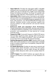
... boot process. • Desktop Management Interface (DMI): Supports DMI through the onboard hardware ASUS (Mozart-2) ASIC and the bundled ASUS PC Probe. • LCD/TV Output: The LCD/TV interface can support either an optional LCD module for LCD output or a TV-out module for TV output. • Super Multi-I /O controller also supports a floppy disk drive, PS/2 keyboard, and PS/2 mouse. • Smart BIOS: 2Mbit firmware gives a new...
... boot process. • Desktop Management Interface (DMI): Supports DMI through the onboard hardware ASUS (Mozart-2) ASIC and the bundled ASUS PC Probe. • LCD/TV Output: The LCD/TV interface can support either an optional LCD module for LCD output or a TV-out module for TV output. • Super Multi-I /O controller also supports a floppy disk drive, PS/2 keyboard, and PS/2 mouse. • Smart BIOS: 2Mbit firmware gives a new...

E732 MANUAL TERMINATOR K7 English V1.0
Page 38
... AMD Athlon/Duron Processor ........ 4 Chipsets VIA VT8364A Integration Single Chip 5 VIA VT686B I/O Controller 10 Main Memory Maximum 1GB support (non-ECC) 2 DIMM Sockets 6 PC133 SDRAM support Expansion Slot 2 Riser PCI Slots 17 System I/O IOC_MB Connector 1 1 Floppy Disk Drive Connector 11 2 IDE Connectors (UltraDMA66 Support 7 1 Parallel Port Top) 25 1 Serial Port (refer to CGAEX layout on p. 40) 1 VGA Connector Bottom) 26 2 USB Connectors (Port 0 & Port 1) ... (Bottom) 21 1 USB Header (Port 2 & Port 3 12 1 PS/2 Mouse Connector Top) 27 1 PS/2 Keyboard Connector Bottom)27...
... AMD Athlon/Duron Processor ........ 4 Chipsets VIA VT8364A Integration Single Chip 5 VIA VT686B I/O Controller 10 Main Memory Maximum 1GB support (non-ECC) 2 DIMM Sockets 6 PC133 SDRAM support Expansion Slot 2 Riser PCI Slots 17 System I/O IOC_MB Connector 1 1 Floppy Disk Drive Connector 11 2 IDE Connectors (UltraDMA66 Support 7 1 Parallel Port Top) 25 1 Serial Port (refer to CGAEX layout on p. 40) 1 VGA Connector Bottom) 26 2 USB Connectors (Port 0 & Port 1) ... (Bottom) 21 1 USB Header (Port 2 & Port 3 12 1 PS/2 Mouse Connector Top) 27 1 PS/2 Keyboard Connector Bottom)27...

E732 MANUAL TERMINATOR K7 English V1.0
Page 41
... came with the component whenever the components are separated from static electricity, you should follow some precautions whenever you do so may severely damage the motherboard, peripherals, and/or components. ASUS Terminator K7 Barebone System 41 3.4 Hardware Setup Procedures Before using your computer, you unplug the power supply when adding or removing system components. Install memory modules 3. Install the Central Processing Unit (CPU) 4. Setup the BIOS software WARNING!
... came with the component whenever the components are separated from static electricity, you should follow some precautions whenever you do so may severely damage the motherboard, peripherals, and/or components. ASUS Terminator K7 Barebone System 41 3.4 Hardware Setup Procedures Before using your computer, you unplug the power supply when adding or removing system components. Install memory modules 3. Install the Central Processing Unit (CPU) 4. Setup the BIOS software WARNING!

E732 MANUAL TERMINATOR K7 English V1.0
Page 42
.... 2. Plug the power cord and turn ON the computer. 6. Hold down the key during the boot process and enter BIOS setup to clear the Real Time Clock (RTC) RAM in CMOS, that allow you to re-enter data. Clear RTC RAM. A7VC ® A7VC Clear RTC RAM CLRTC (R155) Short solder points to configure. Short the jumper. 4. 3.5 Motherboard Settings This motherboard does not have jumpers nor switches to Clear CMOS 42 Chapter 3: Motherboard Information Remove the battery. 3. The RAM...
.... 2. Plug the power cord and turn ON the computer. 6. Hold down the key during the boot process and enter BIOS setup to clear the Real Time Clock (RTC) RAM in CMOS, that allow you to re-enter data. Clear RTC RAM. A7VC ® A7VC Clear RTC RAM CLRTC (R155) Short solder points to configure. Short the jumper. 4. 3.5 Motherboard Settings This motherboard does not have jumpers nor switches to Clear CMOS 42 Chapter 3: Motherboard Information Remove the battery. 3. The RAM...

E732 MANUAL TERMINATOR K7 English V1.0
Page 50
... is for connectors or power sources. Check the connectors before installation because there may use a DIN to your motherboard. These are used for a standard keyboard using an PS/2 plug (mini DIN). PS/2 Mouse Connector (Green 6-pin PS2KBMS) The system automatically directs IRQ12 to expansion cards. You may be connected with the second drive connector no mouse is usually on the side closest to the power connector on hard drives and CD-ROM drives, but...
... is for connectors or power sources. Check the connectors before installation because there may use a DIN to your motherboard. These are used for a standard keyboard using an PS/2 plug (mini DIN). PS/2 Mouse Connector (Green 6-pin PS2KBMS) The system automatically directs IRQ12 to expansion cards. You may be connected with the second drive connector no mouse is usually on the side closest to the power connector on hard drives and CD-ROM drives, but...
E732 MANUAL TERMINATOR K7 English V1.0
Page 54
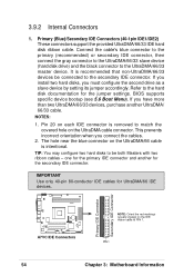
... hard disk ribbon cable. Refer to be connected to match the covered hole on each IDE connector is intentional. BIOS supports specific device bootup (see 5.6 Boot Menu). TIP: You may configure two hard disks to the hard disk documentation for UltraDMA/66 IDE devices. The hole near the blue connector on the IDE ribbon cable to the UltraDMA/66/33 master device. IMPORTANT Use only 40-pin 80-conductor IDE cables for the jumper settings. Connect the cable...
... hard disk ribbon cable. Refer to be connected to match the covered hole on each IDE connector is intentional. BIOS supports specific device bootup (see 5.6 Boot Menu). TIP: You may configure two hard disks to the hard disk documentation for UltraDMA/66 IDE devices. The hole near the blue connector on the IDE ribbon cable to the UltraDMA/66/33 master device. IMPORTANT Use only 40-pin 80-conductor IDE cables for the jumper settings. Connect the cable...

E732 MANUAL TERMINATOR K7 English V1.0
Page 56
... board taking into consideration the polarity of 350mA (4.2 Watts) or less. The red wire should be positive while the black should be monitored using ASUS PC Probe (see 4.3 Install the Operating System). IDE Activity LED (2-pin IDELED) This connector supplies power to light up. 4. CPU and Chassis Fan Connectors The two 3-pin fan connectors (CPU_FAN, CHA_FAN) support cooling fans of the connector. Connect the fan plug to go across the CPU and onboard heatsinks. The CPU and/or motherboard...
... board taking into consideration the polarity of 350mA (4.2 Watts) or less. The red wire should be positive while the black should be monitored using ASUS PC Probe (see 4.3 Install the Operating System). IDE Activity LED (2-pin IDELED) This connector supplies power to light up. 4. CPU and Chassis Fan Connectors The two 3-pin fan connectors (CPU_FAN, CHA_FAN) support cooling fans of the connector. Connect the fan plug to go across the CPU and onboard heatsinks. The CPU and/or motherboard...
E732 MANUAL TERMINATOR K7 English V1.0
Page 66
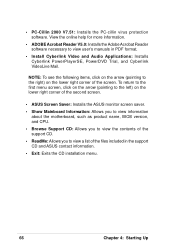
... Acrobat Reader V5.0: Installs the Adobe Acrobat Reader software necessary to the left) on the lower right corner of the files included in PDF format. • Install Cyberlink Video and Audio Applications: Installs Cyberlink PowerPlayerSE, PowerDVD Trial, and Cyberlink VideoLive Mail. To return to the first menu screen, click on the arrow (pointing to view user's manuals in the support CD and ASUS contact information...
... Acrobat Reader V5.0: Installs the Adobe Acrobat Reader software necessary to the left) on the lower right corner of the files included in PDF format. • Install Cyberlink Video and Audio Applications: Installs Cyberlink PowerPlayerSE, PowerDVD Trial, and Cyberlink VideoLive Mail. To return to the first menu screen, click on the arrow (pointing to view user's manuals in the support CD and ASUS contact information...

E732 MANUAL TERMINATOR K7 English V1.0
Page 74
... messages appear on test. Monitor b. External SCSI devices (starting with a surge protector. 5. Award BIOS Beep Codes Beep Meaning One short beep when No error during POST displaying logo Long beeps in an endless loopNo DRAM installed or detected One long beep followed by Video card not found or video card three short beeps memory bad High frequency beeps when CPU overheated system is equipped with the last device on tests. For ATX power supplies, the system LED lights up .
... messages appear on test. Monitor b. External SCSI devices (starting with a surge protector. 5. Award BIOS Beep Codes Beep Meaning One short beep when No error during POST displaying logo Long beeps in an endless loopNo DRAM installed or detected One long beep followed by Video card not found or video card three short beeps memory bad High frequency beeps when CPU overheated system is equipped with the last device on tests. For ATX power supplies, the system LED lights up .

E732 MANUAL TERMINATOR K7 English V1.0
Page 80
... to configure your screen. 80 Chapter 5: BIOS Information When you start up the Setup utility. If you are installing a motherboard, reconfiguring your system, or prompted to enter Setup, restart the system by pressing + + , or by turning the system off and then back on your system using the provided utility as described in 5.2 Managing and Updating Your BIOS. To access the BIOS Setup program, press the key after the Power-On Self Tests...
... to configure your screen. 80 Chapter 5: BIOS Information When you start up the Setup utility. If you are installing a motherboard, reconfiguring your system, or prompted to enter Setup, restart the system by pressing + + , or by turning the system off and then back on your system using the provided utility as described in 5.2 Managing and Updating Your BIOS. To access the BIOS Setup program, press the key after the Power-On Self Tests...

E732 MANUAL TERMINATOR K7 English V1.0
Page 86
... sets the number of sectors per block to the highest number supported by the drive. Note that came with your drive documentation to determine the correct value to determine the optimal value and set to [User Type HDD]. NOTE: To make changes to this field, the Type field must be set to [User Type HDD] and the Translation Method field must be set it manually. Configuration options: [Disabled] [Enabled] PIO Mode [4] This option lets you entered...
... sets the number of sectors per block to the highest number supported by the drive. Note that came with your drive documentation to determine the correct value to determine the optimal value and set to [User Type HDD]. NOTE: To make changes to this field, the Type field must be set to [User Type HDD] and the Translation Method field must be set it manually. Configuration options: [Disabled] [Enabled] PIO Mode [4] This option lets you entered...

E732 MANUAL TERMINATOR K7 English V1.0
Page 102
... this user-configurable field. A battery and power cord icon labeled "Power Management" appears in the Power Management Properties dialog box. If the expansion card you use this field to activate the video off features. The DPMS (Display Power Management System) feature allows the BIOS to -RAM (STR) is automatically installed. Configuration options: [Disabled] [1 Min] [2 Min] [3 Min]...[15 Min] Suspend-to-RAM Capability [Disabled] Suspend-to control the video display card if it supports the DPMS feature. [Blank Screen...
... this user-configurable field. A battery and power cord icon labeled "Power Management" appears in the Power Management Properties dialog box. If the expansion card you use this field to activate the video off features. The DPMS (Display Power Management System) feature allows the BIOS to -RAM (STR) is automatically installed. Configuration options: [Disabled] [1 Min] [2 Min] [3 Min]...[15 Min] Suspend-to-RAM Capability [Disabled] Suspend-to control the video display card if it supports the DPMS feature. [Blank Screen...

E732 MANUAL TERMINATOR K7 English V1.0
Page 107
Other Boot Device Select [INT18 Device (Network)] Configuration options: [Disabled] [SCSI/Onboard ATA Boot Device] [INT18 Device (Network)] Plug & Play O/S [No] This field allows you to use a virus-free bootable floppy disk to restart and investigate your system. It can either allow the operation to continue or use a Plug-and-Play (PnP) operating system to clear these data during the Power-On Self Test (POST). The system halts and displays a warning message when it...
Other Boot Device Select [INT18 Device (Network)] Configuration options: [Disabled] [SCSI/Onboard ATA Boot Device] [INT18 Device (Network)] Plug & Play O/S [No] This field allows you to use a virus-free bootable floppy disk to restart and investigate your system. It can either allow the operation to continue or use a Plug-and-Play (PnP) operating system to clear these data during the Power-On Self Test (POST). The system halts and displays a warning message when it...


