TX97-L User Manual
Page 1
R TX97-L Pentium® Motherboard USER'S MANUAL
R TX97-L Pentium® Motherboard USER'S MANUAL
TX97-L User Manual
Page 4
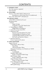
... Processing Unit (CPU 22 4. FEATURES 8 Features of the ASUS TX97-L Motherboard 8 Introduction to ASUS Smart Series of motherboards 9 Parts of Power Management Setup 46 PNP and PCI Setup 48 4 ASUS TX97-L User's Manual INSTALLATION 12 ASUS TX97-L Motherboard Layout 12 Installation Steps 14 1. System Memory (DIMM 19 ...Setup 41 Chipset Features Setup 43 Details of Chipset Features Setup 43 Power Management Setup 46 Details of the ASUS TX97-L Motherboard 11 III. External Connectors 25 Power Connection Procedures 33 IV. Jumpers 14 Jumper Settings 15 Compatible Cyrix ...
... Processing Unit (CPU 22 4. FEATURES 8 Features of the ASUS TX97-L Motherboard 8 Introduction to ASUS Smart Series of motherboards 9 Parts of Power Management Setup 46 PNP and PCI Setup 48 4 ASUS TX97-L User's Manual INSTALLATION 12 ASUS TX97-L Motherboard Layout 12 Installation Steps 14 1. System Memory (DIMM 19 ...Setup 41 Chipset Features Setup 43 Details of Chipset Features Setup 43 Power Management Setup 46 Details of the ASUS TX97-L Motherboard 11 III. External Connectors 25 Power Connection Procedures 33 IV. Jumpers 14 Jumper Settings 15 Compatible Cyrix ...
TX97-L User Manual
Page 5
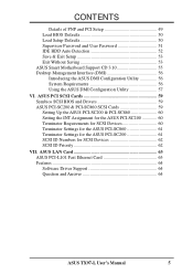
...SCSI Cards 59 Setting Up the ASUS PCI-SC200 & PCI-SC860 60 Setting the INT Assignment for the ASUS PCI-SC200 60 Terminator Requirements for SCSI Devices 60 Terminator Settings for the ASUS PCI-SC860 61 Terminator Settings for the ASUS PCI-SC200 61 SCSI ID ...ASUS Smart Motherboard Support CD 3.10 55 Desktop Management Interface (DMI 56 Introducing the ASUS DMI Configuration Utility 56 System Requirements 56 Using the ASUS DMI Configuration Utility 57 VI. ASUS LAN Card 63 ASUS PCI-L101 Fast Ethernet Card 63 Features 64 Software Driver Support 64 Question and Answer 64 ASUS TX97...
...SCSI Cards 59 Setting Up the ASUS PCI-SC200 & PCI-SC860 60 Setting the INT Assignment for the ASUS PCI-SC200 60 Terminator Requirements for SCSI Devices 60 Terminator Settings for the ASUS PCI-SC860 61 Terminator Settings for the ASUS PCI-SC200 61 SCSI ID ...ASUS Smart Motherboard Support CD 3.10 55 Desktop Management Interface (DMI 56 Introducing the ASUS DMI Configuration Utility 56 System Requirements 56 Using the ASUS DMI Configuration Utility 57 VI. ASUS LAN Card 63 ASUS PCI-L101 Fast Ethernet Card 63 Features 64 Software Driver Support 64 Question and Answer 64 ASUS TX97...
TX97-L User Manual
Page 7
... setting up the BIOS software V. INTRODUCTION How this product III. ASUS L101 Card: Installation of the ASUS LAN card (optional) Item Checklist Please check that your retailer. (1) ASUS Motherboard (1) 9pin male serial + 25pin male serial external connector set .../100 Ethernet Card (optional) ASUS TX97-L User's Manual 7 BIOS Software: Instructions on the included support software VI. Features: Information and specifications concerning this manual is organized This manual is complete. Support Software: Information on setting up the motherboard IV. I . INTRODUCTION (...
... setting up the BIOS software V. INTRODUCTION How this product III. ASUS L101 Card: Installation of the ASUS LAN card (optional) Item Checklist Please check that your retailer. (1) ASUS Motherboard (1) 9pin male serial + 25pin male serial external connector set .../100 Ethernet Card (optional) ASUS TX97-L User's Manual 7 BIOS Software: Instructions on the included support software VI. Features: Information and specifications concerning this manual is organized This manual is complete. Support Software: Information on setting up the motherboard IV. I . INTRODUCTION (...
TX97-L User Manual
Page 8
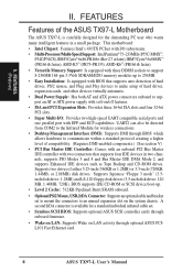
... onboard. • OptionalPS/2Mouse,USB,IrDAConnector: Supportsanoptionalcableandbracket set . • Symbios SCSI BIOS: Supports optional ASUS SCSI controller cards through optional ASUS PCIL101 Fast Ethernet card. 8 ASUS TX97-L User's Manual BIOS supports IDE CD-ROM or SCSI device boot-up to 256MB. • Easy ...) and LS-120 floppy disk drives (3.5-inch disk drive: 120 MB, 1.44MB, 720K). II. Supports two drives of the ASUS TX97-L Motherboard The ASUS TX97-L is available for the demanding PC user who wants many intelligent features in two channels, supports PIO Modes 3 and 4 and ...
... onboard. • OptionalPS/2Mouse,USB,IrDAConnector: Supportsanoptionalcableandbracket set . • Symbios SCSI BIOS: Supports optional ASUS SCSI controller cards through optional ASUS PCIL101 Fast Ethernet card. 8 ASUS TX97-L User's Manual BIOS supports IDE CD-ROM or SCSI device boot-up to 256MB. • Easy ...) and LS-120 floppy disk drives (3.5-inch disk drive: 120 MB, 1.44MB, 720K). II. Supports two drives of the ASUS TX97-L Motherboard The ASUS TX97-L is available for the demanding PC user who wants many intelligent features in two channels, supports PIO Modes 3 and 4 and ...
TX97-L User Manual
Page 9
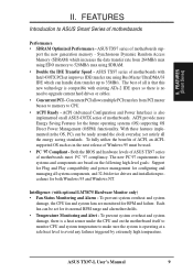
... ACPI, an ACPIsupported OS such as in the OS, PCs can be set for RPM and failure. Both the BIOS and hardware levels of ASUS TX97 series of motherboards Performance • SDRAM Optimized Performance - Each fan can be used. • PC '97 Compliant - To prevent system overheat and system damage, the CPU fan... Alert - FEATURES Introduction to CPU. • ACPI Ready - ACPI provide more Energy Saving Features for both Windows 95 and Windows NT. FEATURES (Smart Series) II. ASUS TX97 series of motherboards. ASUS TX97-L User's Manual 9
... ACPI, an ACPIsupported OS such as in the OS, PCs can be set for RPM and failure. Both the BIOS and hardware levels of ASUS TX97 series of motherboards Performance • SDRAM Optimized Performance - Each fan can be used. • PC '97 Compliant - To prevent system overheat and system damage, the CPU fan... Alert - FEATURES Introduction to CPU. • ACPI Ready - ACPI provide more Energy Saving Features for both Windows 95 and Windows NT. FEATURES (Smart Series) II. ASUS TX97 series of motherboards. ASUS TX97-L User's Manual 9
TX97-L User Manual
Page 10
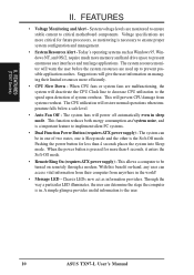
...off automatically even in the world! • Message LED - The system fans will prevent CPU damage from anywhere in sleep mode. FEATURES (TX97 Series) II. FEATURES • Voltage Monitoring and Alert - Today's operating systems such as information providers. A simple glimpse provides useful information ...and OS/2, require much more than 4 seconds places the system into Sleep mode. This allows a computer to critical motherboard components. This function reduces both energy consumption and system noise, and is necessary to the user. 10 ASUS TX97-L User's Manual
...off automatically even in the world! • Message LED - The system fans will prevent CPU damage from anywhere in sleep mode. FEATURES (TX97 Series) II. FEATURES • Voltage Monitoring and Alert - Today's operating systems such as information providers. A simple glimpse provides useful information ...and OS/2, require much more than 4 seconds places the system into Sleep mode. This allows a computer to critical motherboard components. This function reduces both energy consumption and system noise, and is necessary to the user. 10 ASUS TX97-L User's Manual
TX97-L User Manual
Page 11
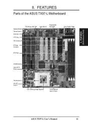
FEATURES (Motherboard Parts) II. FEATURES Parts of the ASUS TX97-L Motherboard Hardware Monitor Thermal Sensor 3 ISA Slots 4 PCI Slots IDE Connectors AT Power Connector Programmable PS/2 Mouse, USB, IrDA Super Multi-I/O Flash ROM ATX Power Serial, Parallel, Floppy 3 DIMM Sockets Intel's 430TX PCIset Thermal Sensor CPU ZIF Socket 7 "Cool" Switching Voltage Regulators 512KB Pipelined Burst L2 Cache ASUS TX97-L User's Manual 11 II.
FEATURES (Motherboard Parts) II. FEATURES Parts of the ASUS TX97-L Motherboard Hardware Monitor Thermal Sensor 3 ISA Slots 4 PCI Slots IDE Connectors AT Power Connector Programmable PS/2 Mouse, USB, IrDA Super Multi-I/O Flash ROM ATX Power Serial, Parallel, Floppy 3 DIMM Sockets Intel's 430TX PCIset Thermal Sensor CPU ZIF Socket 7 "Cool" Switching Voltage Regulators 512KB Pipelined Burst L2 Cache ASUS TX97-L User's Manual 11 II.
TX97-L User Manual
Page 12
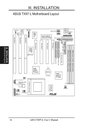
...Intel 430TX PCIset FS2 FS1 FS0 512KB PB L2 Cache Row 5 4 3 2 1 0 Clock Freq R Infrared Panel Connectors 12 ASUS TX97-L User's Manual INSTALLATION (Motherboard Layout) III. III. INSTALLATION ASUS TX97-L Motherboard Layout ISA Slot 3 Boot Block Write Hardware Monitor Thermal LM78 Sensor PS/2 Mouse, USB, IrDA Super Multi-I/O COM 1 Serial ... on LAN Power Fan Floppy Drives ISA Slot 1 ISA Slot 2 P9 AT Power Input PCI Slot 1 PCI Slot 2 PCI Slot 3 PCI Slot 4 ASUS ASIC DIMM Socket 1 (64-bit, 168-pin module) DIMM Socket 2 (64-bit, 168-pin module) DIMM Socket 3 (64-bit, 168-pin ...
...Intel 430TX PCIset FS2 FS1 FS0 512KB PB L2 Cache Row 5 4 3 2 1 0 Clock Freq R Infrared Panel Connectors 12 ASUS TX97-L User's Manual INSTALLATION (Motherboard Layout) III. III. INSTALLATION ASUS TX97-L Motherboard Layout ISA Slot 3 Boot Block Write Hardware Monitor Thermal LM78 Sensor PS/2 Mouse, USB, IrDA Super Multi-I/O COM 1 Serial ... on LAN Power Fan Floppy Drives ISA Slot 1 ISA Slot 2 P9 AT Power Input PCI Slot 1 PCI Slot 2 PCI Slot 3 PCI Slot 4 ASUS ASIC DIMM Socket 1 (64-bit, 168-pin module) DIMM Socket 2 (64-bit, 168-pin module) DIMM Socket 3 (64-bit, 168-pin ...
TX97-L User Manual
Page 13
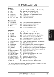
ASUS TX97-L User's Manual 13 INSTALLATION Jumpers 1) BBLKW 2) CLRTC 3) KBWK 4) FS0, FS1, FS2 5) BF0, BF1, BF2 6) VID0, VID1, VID2 p. 15 Flash ROM Boot Block Program (Disable/Enable) p. ... Chassis Open Alarm Lead (4-1pin Block) p. 28 Primary / Secondary IDE Connector (40-1pin Blocks) p. 28 IDE LED Activity Light p. 29 ATX Motherboard Power Connector (20-pin Block) p. 29 AT Motherboard Power Connector (12-pin Block) p. 31 PS/2 Mouse/USB/IR Combo-Connector (18-1pin Block) p. 31 Second Infrared Port Module Connector (5-pin...
ASUS TX97-L User's Manual 13 INSTALLATION Jumpers 1) BBLKW 2) CLRTC 3) KBWK 4) FS0, FS1, FS2 5) BF0, BF1, BF2 6) VID0, VID1, VID2 p. 15 Flash ROM Boot Block Program (Disable/Enable) p. ... Chassis Open Alarm Lead (4-1pin Block) p. 28 Primary / Secondary IDE Connector (40-1pin Blocks) p. 28 IDE LED Activity Light p. 29 ATX Motherboard Power Connector (20-pin Block) p. 29 AT Motherboard Power Connector (12-pin Block) p. 31 PS/2 Mouse/USB/IR Combo-Connector (18-1pin Block) p. 31 Second Infrared Port Module Connector (5-pin...
TX97-L User Manual
Page 14
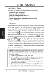
... grounded wrist strap before handling computer components. INSTALLATION Installation Steps Before using your computer when working on the left when holding the motherboard with three pins. The jumper settings will be described numerically, such as to connect pins 1&2 and to connect pins 2&3. The...Cards 5. A "1" is always on top or on the inside. 2. Computer motherboards, baseboards and components, such as the power supply case. 3. To protect them against damage from the system. 14 ASUS TX97-L User's Manual Place components on a grounded antistatic pad or on the bag ...
... grounded wrist strap before handling computer components. INSTALLATION Installation Steps Before using your computer when working on the left when holding the motherboard with three pins. The jumper settings will be described numerically, such as to connect pins 1&2 and to connect pins 2&3. The...Cards 5. A "1" is always on top or on the inside. 2. Computer motherboards, baseboards and components, such as the power supply case. 3. To protect them against damage from the system. 14 ASUS TX97-L User's Manual Place components on a grounded antistatic pad or on the bag ...
TX97-L User Manual
Page 17
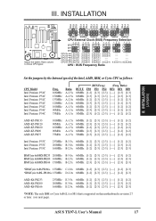
...[1-2] [2-3] [2-3] 60MHz [2-3] [2-3] [2-3] 50MHz [2-3] [1-2] [2-3] (Freq. III. INSTALLATION FS2 FS1 FS0 FS2 FS1 FS0 FS2 FS1 FS0 FS2 FS1 FS0 FS2 FS1 FS0 FS2 FS1 FS0 III. ASUS TX97-L User's Manual 17 Ratio) BF2 BF1 BF0 [----] [2-3] [2-3] [----] [2-3] [2-3] [----] [1-2] [2-3] [----] [1-2] [2-3] [----] [1-2] [1-2] [----] [1-2] [1-2] [----] [1-2] [1-2] AMD-K5-PR133 AMD-K5-PR120... [2-3] [----] [2-3] [1-2] 166MHz E-2.5x 66MHz [1-2] [2-3] [2-3] [----] [2-3] [2-3] *NOTE: The only IBM or Cyrix 6x86(L) (or M1) that is supported on this motherboard is revision 2.7 or later. (see next page).
...[1-2] [2-3] [2-3] 60MHz [2-3] [2-3] [2-3] 50MHz [2-3] [1-2] [2-3] (Freq. III. INSTALLATION FS2 FS1 FS0 FS2 FS1 FS0 FS2 FS1 FS0 FS2 FS1 FS0 FS2 FS1 FS0 FS2 FS1 FS0 III. ASUS TX97-L User's Manual 17 Ratio) BF2 BF1 BF0 [----] [2-3] [2-3] [----] [2-3] [2-3] [----] [1-2] [2-3] [----] [1-2] [2-3] [----] [1-2] [1-2] [----] [1-2] [1-2] [----] [1-2] [1-2] AMD-K5-PR133 AMD-K5-PR120... [2-3] [----] [2-3] [1-2] 166MHz E-2.5x 66MHz [1-2] [2-3] [2-3] [----] [2-3] [2-3] *NOTE: The only IBM or Cyrix 6x86(L) (or M1) that is supported on this motherboard is revision 2.7 or later. (see next page).
TX97-L User Manual
Page 18
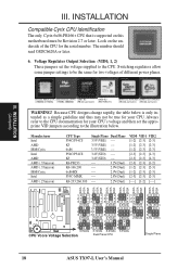
... only Cyrix 6x86-PR166+ CPU that is only intended as a simple guideline and thus may not be Revision 2.7 or later. Look on this motherboard must be true for your CPU's voltage and then set the voltage supplied to the illustration below is supported on the underside of different power... 1 1 1 2 2 2 2 2 3 3 3 3 3 2.5Volts 2.6Volts 2.7Volts 2.8Volts 2.9Volts Thermal Sensor R 1 1 1 1 2 2 2 2 3 3 3 3 3.0Volts 3.1Volts 3.2Volts 3.3Volts CPU Vcore Voltage Selection Dual Plane CPU 1 2 3 3.4V (STD) 1 2 3 3.5V (VRE) Single Plane 18 ASUS TX97-L User's Manual
... only Cyrix 6x86-PR166+ CPU that is only intended as a simple guideline and thus may not be Revision 2.7 or later. Look on this motherboard must be true for your CPU's voltage and then set the voltage supplied to the illustration below is supported on the underside of different power... 1 1 1 2 2 2 2 2 3 3 3 3 3 2.5Volts 2.6Volts 2.7Volts 2.8Volts 2.9Volts Thermal Sensor R 1 1 1 1 2 2 2 2 3 3 3 3 3.0Volts 3.1Volts 3.2Volts 3.3Volts CPU Vcore Voltage Selection Dual Plane CPU 1 2 3 3.4V (STD) 1 2 3 3.5V (VRE) Single Plane 18 ASUS TX97-L User's Manual
TX97-L User Manual
Page 19
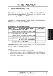
...18 chips will case unstable operation. Slot 3 must be empty Socket 2 SDRAM/EDO 8MB, 16MB, 32MB x1 SDRAM/EDO 64, 128, 256MB - ASUS TX97-L User's Manual 19 Maximum memory of the BIOS SOFTWARE. Slot 3 must be 256MB or less. Memory modules with 64Mbit SDRAM cells, Socket 3 must ... = WARNING: Memory modules must be empty. Install memory in BIOS Chipset Setup of DIMMs must have 18 chips or less. System Memory (DIMM) This motherboard has three sockets to support 3.3Volt (power level) Unbuffered Synchronous DRAMs (SDRAM) DIMMs of either 8, 16, or 32, 64, 128, or 256MB....
...18 chips will case unstable operation. Slot 3 must be empty Socket 2 SDRAM/EDO 8MB, 16MB, 32MB x1 SDRAM/EDO 64, 128, 256MB - ASUS TX97-L User's Manual 19 Maximum memory of the BIOS SOFTWARE. Slot 3 must be 256MB or less. Memory modules with 64Mbit SDRAM cells, Socket 3 must ... = WARNING: Memory modules must be empty. Install memory in BIOS Chipset Setup of DIMMs must have 18 chips or less. System Memory (DIMM) This motherboard has three sockets to support 3.3Volt (power level) Unbuffered Synchronous DRAMs (SDRAM) DIMMs of either 8, 16, or 32, 64, 128, or 256MB....
TX97-L User Manual
Page 21
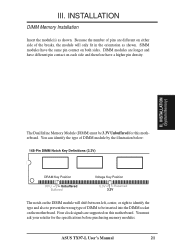
ASUS TX97-L User's Manual 21 Because the number of pins are different on either... purchasing memory modules. INSTALLATION (System Memory) The Dual Inline Memory Module (DIMM) must ask your retailer for this motherboard. III. You can identify the type of DIMM module by the illustration below: 168-Pin DIMM Notch Key Definitions ...(3.3V) DRAM Key Position RFU Unbuffered Buffered Voltage Key Position 5.0V Reserved 3.3V The notch on the motherboard. SIMM modules have a higher pin density. III. Four clock signals are longer and have different pin contact on...
ASUS TX97-L User's Manual 21 Because the number of pins are different on either... purchasing memory modules. INSTALLATION (System Memory) The Dual Inline Memory Module (DIMM) must ask your retailer for this motherboard. III. You can identify the type of DIMM module by the illustration below: 168-Pin DIMM Notch Key Definitions ...(3.3V) DRAM Key Position RFU Unbuffered Buffered Voltage Key Position 5.0V Reserved 3.3V The notch on the motherboard. SIMM modules have a higher pin density. III. Four clock signals are longer and have different pin contact on...
TX97-L User Manual
Page 22
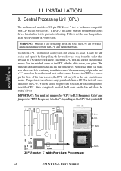
... in the one hole is not the case then purchase a fan before you turn off your system. III. Central Processing Unit (CPU) The motherboard provides a 321-pin ZIF Socket 7 that corner of the square array of the lever. If this is missing from the socket then upwards to...has a corner pin for "BUS Frequency Selection" depending on the motherboard next to insert the CPU. Without a fan circulating air on the fan and close the socket's lever. you install. WARNING! Insert the CPU with Pentium Processor 22 ASUS TX97-L User's Manual With the added weight of the CPU. The ...
... in the one hole is not the case then purchase a fan before you turn off your system. III. Central Processing Unit (CPU) The motherboard provides a 321-pin ZIF Socket 7 that corner of the square array of the lever. If this is missing from the socket then upwards to...has a corner pin for "BUS Frequency Selection" depending on the motherboard next to insert the CPU. Without a fan circulating air on the fan and close the socket's lever. you install. WARNING! Insert the CPU with Pentium Processor 22 ASUS TX97-L User's Manual With the added weight of the CPU. The ...
TX97-L User Manual
Page 23
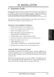
...use . Both ISA and PCI expansion cards may cause severe damage to setup your specific card. System IRQs are available to operate. Remove your motherboard and expansion cards. Setup the BIOS if necessary (such as "IRQ xx Used By ISA: Yes" in step 4. 7. Currently, there are... expansion cards need to use by PCI cards. Carefully align the card's connectors and press firmly. 6. Assigning IRQs for your expansion card. ASUS TX97-L User's Manual 23 Set any necessary jumpers on any remaining IRQs are two types of the system which leaves 6 free for expansion cards....
...use . Both ISA and PCI expansion cards may cause severe damage to setup your specific card. System IRQs are available to operate. Remove your motherboard and expansion cards. Setup the BIOS if necessary (such as "IRQ xx Used By ISA: Yes" in step 4. 7. Currently, there are... expansion cards need to use by PCI cards. Carefully align the card's connectors and press firmly. 6. Assigning IRQs for your expansion card. ASUS TX97-L User's Manual 23 Set any necessary jumpers on any remaining IRQs are two types of the system which leaves 6 free for expansion cards....
TX97-L User Manual
Page 24
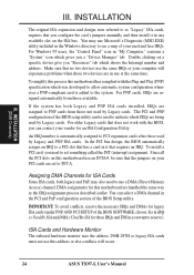
...the PCI bus design, the BIOS automatically assigns an IRQ to reserve). IMPORTANT: To avoid conflicts, reserve the necessary IRQs and DMAs for this motherboard use a DMA (Direct Memory Access) channel. Since all the PCI slots on a specific device give you need to as the IRQ assignment ...this motherboard has complied with the BIOS, you want to a PCI slot that no two devices use at the same time. The PCI and PNP configuration of the BIOS setup utility can select a DMA channel in the PCI and PnP configuration section of your computer will occur. 24 ASUS TX97-L...
...the PCI bus design, the BIOS automatically assigns an IRQ to reserve). IMPORTANT: To avoid conflicts, reserve the necessary IRQs and DMAs for this motherboard use a DMA (Direct Memory Access) channel. Since all the PCI slots on a specific device give you need to as the IRQ assignment ...this motherboard has complied with the BIOS, you want to a PCI slot that no two devices use at the same time. The PCI and PNP configuration of the BIOS setup utility can select a DMA channel in the PCI and PnP configuration section of your computer will occur. 24 ASUS TX97-L...
TX97-L User Manual
Page 25
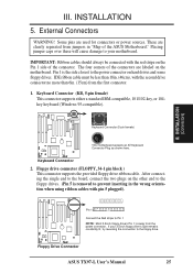
... your 3.5inch floppy drive's light remains constantly lit, try reversing the connection to the board, connect the two plugs on the Pin 1 side of the ASUS Motherboard." The four corners of the connectors are labeled on hard drives and some floppy drives. Pin 1 is the side closest to prevent inserting in "Map...). Floppy drive connector (FLOPPY, 34-1 pin block ) This connector supports the provided floppy drive ribbon cable. After connecting the single end to the floppy drive. ASUS TX97-L User's Manual 25 INSTALLATION 5. If your motherboard.
... your 3.5inch floppy drive's light remains constantly lit, try reversing the connection to the board, connect the two plugs on the Pin 1 side of the ASUS Motherboard." The four corners of the connectors are labeled on hard drives and some floppy drives. Pin 1 is the side closest to prevent inserting in "Map...). Floppy drive connector (FLOPPY, 34-1 pin block ) This connector supports the provided floppy drive ribbon cable. After connecting the single end to the floppy drive. ASUS TX97-L User's Manual 25 INSTALLATION 5. If your motherboard.
TX97-L User Manual
Page 27
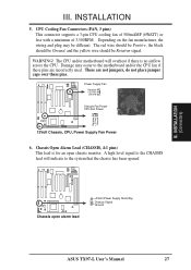
...A high level signal to the CHASSIS lead will overheat if there is for an open alarm lead +5Volt (Power Supply Stand By) Chassis Signal Ground ASUS TX97-L User's Manual 27 INSTALLATION 5. WARNING! Power Supply Fan Rotation +12 Volt Ground Chassis Fan Power CPU Fan Power Thermal Sensor R 12Volt Chassis, CPU...be different. Chassis Open Alarm Lead (CHASSIS, 4-1 pins) This lead is no airflow across the CPU. The CPU and/or motherboard will indicate to the motherboard and/or the CPU fan if these pins are not jumpers, do not place jumper caps over these pins. These are incorrectly ...
...A high level signal to the CHASSIS lead will overheat if there is for an open alarm lead +5Volt (Power Supply Stand By) Chassis Signal Ground ASUS TX97-L User's Manual 27 INSTALLATION 5. WARNING! Power Supply Fan Rotation +12 Volt Ground Chassis Fan Power CPU Fan Power Thermal Sensor R 12Volt Chassis, CPU...be different. Chassis Open Alarm Lead (CHASSIS, 4-1 pins) This lead is no airflow across the CPU. The CPU and/or motherboard will indicate to the motherboard and/or the CPU fan if these pins are not jumpers, do not place jumper caps over these pins. These are incorrectly ...


