TX97-L User Manual
Page 7
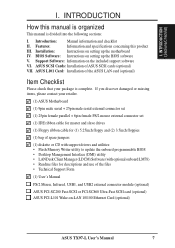
.... ASUS L101 Card: Installation of the ASUS LAN card (optional) Item Checklist Please check that your retailer. (1) ASUS Motherboard (1) 9pin male serial + 25pin male serial external connector set (1) 25pin female parallel + 6pin female PS/2 mouse external connector set (1) IDE ribbon cable for master and slave drives (1) Floppy ribbon cable for (1) 5.25inch floppy and (2) 3.5inch floppies (1) bag of spare jumpers (1) diskette or CD with support drivers and utilities: • Flash Memory Writer utility to update the onboard programmable BIOS • Desktop Management Interface (DMI) utility...
.... ASUS L101 Card: Installation of the ASUS LAN card (optional) Item Checklist Please check that your retailer. (1) ASUS Motherboard (1) 9pin male serial + 25pin male serial external connector set (1) 25pin female parallel + 6pin female PS/2 mouse external connector set (1) IDE ribbon cable for master and slave drives (1) Floppy ribbon cable for (1) 5.25inch floppy and (2) 3.5inch floppies (1) bag of spare jumpers (1) diskette or CD with support drivers and utilities: • Flash Memory Writer utility to update the onboard programmable BIOS • Desktop Management Interface (DMI) utility...
TX97-L User Manual
Page 8
...-ROM or SCSI device boot-up to 256MB. • Easy Installation: Is equipped with two connectors that supports four IDE devices in a small package. Supports two drives of compatibility. (Requires DMI-enabled components.) (See section V) • PCI Bus Master IDE Controller: Comes with an onboard PCI Bus Master IDE controller with BIOS that supports auto detection of hard drives, PS/2 mouse, and Plug and Play devices to make setup of hard drives, expansion cards, and other devices virtually automatic. • Dual Power Supply: Has both AT and ATX power connectors onboard...
...-ROM or SCSI device boot-up to 256MB. • Easy Installation: Is equipped with two connectors that supports four IDE devices in a small package. Supports two drives of compatibility. (Requires DMI-enabled components.) (See section V) • PCI Bus Master IDE Controller: Comes with an onboard PCI Bus Master IDE controller with BIOS that supports auto detection of hard drives, PS/2 mouse, and Plug and Play devices to make setup of hard drives, expansion cards, and other devices virtually automatic. • Dual Power Supply: Has both AT and ATX power connectors onboard...
TX97-L User Manual
Page 9
...- ASUS TX97-L User's Manual 9 Synchronous Dynamic Random Access Memory (SDRAM) which can be ready around the clock everyday, yet satisfy all ASUS 430TX series of motherboards Performance • SDRAM Optimized Performance - ACPI (Advanced Configuration and Power Interface) is also implemented on the following high-level goals: Support for Plug and Play compatibility and power management for configuring and managing all is that this new technology is compatible with optional LM78/75 Hardware Monitor...
...- ASUS TX97-L User's Manual 9 Synchronous Dynamic Random Access Memory (SDRAM) which can be ready around the clock everyday, yet satisfy all ASUS 430TX series of motherboards Performance • SDRAM Optimized Performance - ACPI (Advanced Configuration and Power Interface) is also implemented on the following high-level goals: Support for Plug and Play compatibility and power management for configuring and managing all is that this new technology is compatible with optional LM78/75 Hardware Monitor...
TX97-L User Manual
Page 12
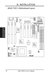
... Voltage Chassis Fan CPU ZIF Socket 7 Intel PIIX4 PCIset Thermal Sensor CR2032 3V Lithium Cell BIOS Power Intel 430TX PCIset FS2 FS1 FS0 512KB PB L2 Cache Row 5 4 3 2 1 0 Clock Freq R Infrared Panel Connectors 12 ASUS TX97-L User's Manual III. INSTALLATION ASUS TX97-L Motherboard Layout ISA Slot 3 Boot Block Write Hardware Monitor Thermal LM78 Sensor PS/2 Mouse, USB, IrDA Super Multi-I/O COM 1 Serial Ports COM 2 Keyboard Keyboard Power System BIOS Flash EEPROM Parallel (Printer) Port Wake on LAN Power Fan Floppy Drives ISA Slot 1 ISA Slot 2 P9 AT Power Input PCI...
... Voltage Chassis Fan CPU ZIF Socket 7 Intel PIIX4 PCIset Thermal Sensor CR2032 3V Lithium Cell BIOS Power Intel 430TX PCIset FS2 FS1 FS0 512KB PB L2 Cache Row 5 4 3 2 1 0 Clock Freq R Infrared Panel Connectors 12 ASUS TX97-L User's Manual III. INSTALLATION ASUS TX97-L Motherboard Layout ISA Slot 3 Boot Block Write Hardware Monitor Thermal LM78 Sensor PS/2 Mouse, USB, IrDA Super Multi-I/O COM 1 Serial Ports COM 2 Keyboard Keyboard Power System BIOS Flash EEPROM Parallel (Printer) Port Wake on LAN Power Fan Floppy Drives ISA Slot 1 ISA Slot 2 P9 AT Power Input PCI...
TX97-L User Manual
Page 13
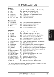
... DIMM Sockets 2) CPU ZIF Socket 7 3) SLOT 1, 2, 3 4) PCI 1, 2, 3, 4 p. 19 168-Pin DIMM Memory Expansion Sockets p. 22 Central Processing Unit (CPU) Socket p. 23 16-bit ISA Bus Expansion Slots* p. 23 32-bit PCI Bus Expansion Slots Connectors 1) KB 2) FLOPPY 3) PRINTER 4) COM1, COM2 5) FAN 6) CHASSIS 7) Primary / Second IDE 8) IDELED 9) ATX POWER 10) AT POWER 11) USBIRMS 12) IR 13) MSG.LED (PANEL) 14) SMI (PANEL) 15) PWR SW. (PANEL) 16) RESET (PANEL) 17) PWR.LED (PANEL) 18) KEYLOCK (PANEL) 19) SPEAKER (PANEL) 20) W0LCON p. 25 Keyboard Connector (5-pin Female) p. 25 Floppy Drive Connector (34...
... DIMM Sockets 2) CPU ZIF Socket 7 3) SLOT 1, 2, 3 4) PCI 1, 2, 3, 4 p. 19 168-Pin DIMM Memory Expansion Sockets p. 22 Central Processing Unit (CPU) Socket p. 23 16-bit ISA Bus Expansion Slots* p. 23 32-bit PCI Bus Expansion Slots Connectors 1) KB 2) FLOPPY 3) PRINTER 4) COM1, COM2 5) FAN 6) CHASSIS 7) Primary / Second IDE 8) IDELED 9) ATX POWER 10) AT POWER 11) USBIRMS 12) IR 13) MSG.LED (PANEL) 14) SMI (PANEL) 15) PWR SW. (PANEL) 16) RESET (PANEL) 17) PWR.LED (PANEL) 18) KEYLOCK (PANEL) 19) SPEAKER (PANEL) 20) W0LCON p. 25 Keyboard Connector (5-pin Female) p. 25 Floppy Drive Connector (34...
TX97-L User Manual
Page 14
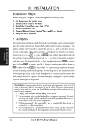
... ASUS TX97-L User's Manual WARNING! Set Jumpers on jumpers with the keyboard connector away from other components. 4. See motherboard layout for our mother- Install Expansion Cards 5. Jumpers Several hardware settings are separated from static electricity, you should follow some precautions whenever you do not have one, touch both jumpers be described numerically, such as the power supply case. 3. A "1" is always on top or on the inside. 2. Use the diagrams in this manual instead...
... ASUS TX97-L User's Manual WARNING! Set Jumpers on jumpers with the keyboard connector away from other components. 4. See motherboard layout for our mother- Install Expansion Cards 5. Jumpers Several hardware settings are separated from static electricity, you should follow some precautions whenever you do not have one, touch both jumpers be described numerically, such as the power supply case. 3. A "1" is always on top or on the inside. 2. Use the diagrams in this manual instead...
TX97-L User Manual
Page 16
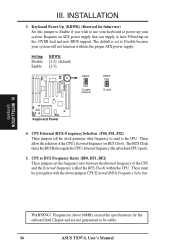
... an ATX power supply that can supply at least 300mAmp on the +5VSB lead and new BIOS support. INSTALLATION 3. Setting Disable Enable KBWK [1-2] (default) [2-3] KBWK 1 2 3 Disable (Default) KBWK 1 2 3 Enable Thermal Sensor R Keyboard Power 4. INSTALLATION (Jumpers) WARNING! The BUS Clock times the BUS Ratio equals the CPU's Internal frequency (the advertised CPU speed). 5. III. Keyboard Power Up (KBWK) (Reserved for the onboard Intel Chipset and are not guaranteed to be set together with the above 66MHz exceed the specifications for future use) Set this jumper to Enable...
... an ATX power supply that can supply at least 300mAmp on the +5VSB lead and new BIOS support. INSTALLATION 3. Setting Disable Enable KBWK [1-2] (default) [2-3] KBWK 1 2 3 Disable (Default) KBWK 1 2 3 Enable Thermal Sensor R Keyboard Power 4. INSTALLATION (Jumpers) WARNING! The BUS Clock times the BUS Ratio equals the CPU's Internal frequency (the advertised CPU speed). 5. III. Keyboard Power Up (KBWK) (Reserved for the onboard Intel Chipset and are not guaranteed to be set together with the above 66MHz exceed the specifications for future use) Set this jumper to Enable...

TX97-L User Manual
Page 23
... types of ISA cards. Secure the card on any hardware and software settings that you unplug your power supply when adding or removing expansion cards or other system components. System IRQs are available to use . INSTALLATION 4. Expansion Card Installation Procedure: 1. Currently, there are then used by parts of them are already in the ISA expansion bus first, and any necessary jumpers on the slot you removed in PNP AND PCI SETUP) 9. Remove...
... types of ISA cards. Secure the card on any hardware and software settings that you unplug your power supply when adding or removing expansion cards or other system components. System IRQs are available to use . INSTALLATION 4. Expansion Card Installation Procedure: 1. Currently, there are then used by parts of them are already in the ISA expansion bus first, and any necessary jumpers on the slot you removed in PNP AND PCI SETUP) 9. Remove...
TX97-L User Manual
Page 29
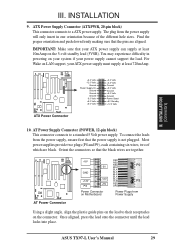
.... AT Power Supply Connector (POWER, 12-pin block) This connector connects to a ATX power supply. Thermal Sensor R AT Power Connector +5V -5V GND +12V PG -12V +5V Power Connector on Motherboard RED RED RED P9 WHT BLK BLK BLK BLK BLU YLW P8 RED ORG Power Plugs from the power supply, ensure first that your ATX power supply must supply at least 10mAmp on LAN support, your ATX power supply can supply at least 720mAmp. ASUS TX97-L User's Manual 29 III. For Wake on...
.... AT Power Supply Connector (POWER, 12-pin block) This connector connects to a ATX power supply. Thermal Sensor R AT Power Connector +5V -5V GND +12V PG -12V +5V Power Connector on Motherboard RED RED RED P9 WHT BLK BLK BLK BLK BLU YLW P8 RED ORG Power Plugs from the power supply, ensure first that your ATX power supply must supply at least 10mAmp on LAN support, your ATX power supply can supply at least 720mAmp. ASUS TX97-L User's Manual 29 III. For Wake on...

TX97-L User Manual
Page 31
... default setting of rebooting in sleep mode. 18. INSTALLATION (Connectors) Message LED +5V GND SMI Lead GND ATX Power GND Switch* Reset SW GND +5V NC Power LED & GND LOCK Keyboard Lock GND +5V GND Speaker GND Connector SPKR Thermal Sensor R System Panel Connectors * Requires an ATX power supply, optional ATX to the case-mounted suspend switch. ASUS TX97-L User's Manual 31 III. This function requires ACPI OS support. 14. SMI Suspend Switch Lead (SMI, 2 pins) This allows the user to turn the system off. Wake...
... default setting of rebooting in sleep mode. 18. INSTALLATION (Connectors) Message LED +5V GND SMI Lead GND ATX Power GND Switch* Reset SW GND +5V NC Power LED & GND LOCK Keyboard Lock GND +5V GND Speaker GND Connector SPKR Thermal Sensor R System Panel Connectors * Requires an ATX power supply, optional ATX to the case-mounted suspend switch. ASUS TX97-L User's Manual 31 III. This function requires ACPI OS support. 14. SMI Suspend Switch Lead (SMI, 2 pins) This allows the user to turn the system off. Wake...
TX97-L User Manual
Page 33
... you use Windows 95, click the Start button, click Shut Down, and then click Shut down with "green" standards or if it complies with ATX power supplies. ASUS TX97-L User's Manual 33 INSTALLATION (Power Connections) III. You may have failed a power-on tests. If you turn on the power, the system may then turn off after Windows shuts down your retailer for assistance. 7. The system will light when the ATX power switch is...
... you use Windows 95, click the Start button, click Shut Down, and then click Shut down with "green" standards or if it complies with ATX power supplies. ASUS TX97-L User's Manual 33 INSTALLATION (Power Connections) III. You may have failed a power-on tests. If you turn on the power, the system may then turn off after Windows shuts down your retailer for assistance. 7. The system will light when the ATX power switch is...
TX97-L User Manual
Page 34
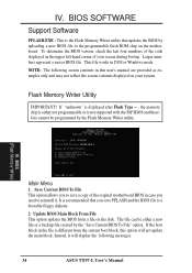
... current boot block, this user's manual are provided as examples only and may not reflect the screen contents displayed on the motherboard. If "unknown" is displayed after Flash Type -- , the memory chip is either a new file or a backup file created by the Flash Memory Writer utility. This file works in the file is the Flash Memory Writer utility that you need to the programmable flash ROM chip on your screen during bootup. Instead, it . BIOS (Flash Memory Writer) Main Menu 1. IV. BIOS SOFTWARE Support Software...
... current boot block, this user's manual are provided as examples only and may not reflect the screen contents displayed on the motherboard. If "unknown" is displayed after Flash Type -- , the memory chip is either a new file or a backup file created by the Flash Memory Writer utility. This file works in the file is the Flash Memory Writer utility that you need to the programmable flash ROM chip on your screen during bootup. Instead, it . BIOS (Flash Memory Writer) Main Menu 1. IV. BIOS SOFTWARE Support Software...
TX97-L User Manual
Page 36
... Main Menu. Boot from the internet (WWW), FTP, or a BBS (Bulletin Board Service) and save to enter BIOS setup. If the Flash Memory Writer utility was not able to boot up . Download an updated ASUS BIOS file from the floppy diskette you created above. Enter 2 "Update BIOS Main Block From File" from the Main Menu or option 2 "Update BIOS Including Boot Block and ESCD" from your Motherboard's BIOS Upon first use of the new BIOS, and then press the key. If you encounter problems while updating...
... Main Menu. Boot from the internet (WWW), FTP, or a BBS (Bulletin Board Service) and save to enter BIOS setup. If the Flash Memory Writer utility was not able to boot up . Download an updated ASUS BIOS file from the floppy diskette you created above. Enter 2 "Update BIOS Main Block From File" from the Main Menu or option 2 "Update BIOS Including Boot Block and ESCD" from your Motherboard's BIOS Upon first use of the new BIOS, and then press the key. If you encounter problems while updating...
TX97-L User Manual
Page 37
... be updated when BIOS upgrades are a little bit late pressing the mentioned key(s), POST will continue with its test routines, thus preventing you invoke Setup, the CMOS SETUP UTILITY main program screen will need to enter new setup information. But do so only if the first two methods fail. BIOS SOFTWARE 6. Use the Flash Memory Writer utility to run this program. BIOS (BIOS Setup) ASUS TX97-L User's Manual 37 Press to configure your motherboard came in particular, the hard disk specifications. When...
... be updated when BIOS upgrades are a little bit late pressing the mentioned key(s), POST will continue with its test routines, thus preventing you invoke Setup, the CMOS SETUP UTILITY main program screen will need to enter new setup information. But do so only if the first two methods fail. BIOS SOFTWARE 6. Use the Flash Memory Writer utility to run this program. BIOS (BIOS Setup) ASUS TX97-L User's Manual 37 Press to configure your motherboard came in particular, the hard disk specifications. When...
TX97-L User Manual
Page 38
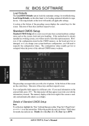
... you change your system hardware configuration, you need . The memory display at the bottom of the screen is for loading optimized defaults for troubleshooting. Follow the month, day and year format. A section at the lower right of the preceding screen displays the control keys for month, day and year are the control keys. Load Setup Defaults, on the selected field, press . IV. BIOS SOFTWARE Load Defaults The Load BIOS Defaults option loads the minimum settings for regular use.
... you change your system hardware configuration, you need . The memory display at the bottom of the screen is for loading optimized defaults for troubleshooting. Follow the month, day and year format. A section at the lower right of the preceding screen displays the control keys for month, day and year are the control keys. Load Setup Defaults, on the selected field, press . IV. BIOS SOFTWARE Load Defaults The Load BIOS Defaults option loads the minimum settings for regular use.
TX97-L User Manual
Page 42
... PS/2 Mouse. The default setting is always the boot disk using a SCSI hard disk drive. PS/2 Mouse Function Control (Auto) The setting of Read Only to only allow reads from ROM to RAM enhances system performance, as graphics accelerators or MPEG Video Cards may not show colors properly. Otherwise leave this problem. BIOS (BIOS Features) 42 ASUS TX97-L User's Manual BIOS SOFTWARE HDD Sequence SCSI/IDE First (IDE) When using OS/2 operating systems with installed DRAM of Disabled...Video ROM BIOS Shadow (Enabled) This field allows...
... PS/2 Mouse. The default setting is always the boot disk using a SCSI hard disk drive. PS/2 Mouse Function Control (Auto) The setting of Read Only to only allow reads from ROM to RAM enhances system performance, as graphics accelerators or MPEG Video Cards may not show colors properly. Otherwise leave this problem. BIOS (BIOS Features) 42 ASUS TX97-L User's Manual BIOS SOFTWARE HDD Sequence SCSI/IDE First (IDE) When using OS/2 operating systems with installed DRAM of Disabled...Video ROM BIOS Shadow (Enabled) This field allows...
TX97-L User Manual
Page 47
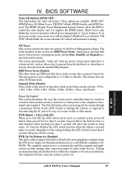
... Function disables the ATX switch function when the button is user-configurable to powering off button when pressed for powering up " from the enabled IRQ channels. If set the period of time after a period of the setting, holding the ATX switch for the Power Management scheme. Regardless of inactivity. The Soft-Off mode refers to 1-15 Mins or Disable. BIOS (Power Management) ASUS TX97-L User's Manual 47 This feature does not affect SCSI hard disks. HDD Power Down (Disable...
... Function disables the ATX switch function when the button is user-configurable to powering off button when pressed for powering up " from the enabled IRQ channels. If set the period of time after a period of the setting, holding the ATX switch for the Power Management scheme. Regardless of inactivity. The Soft-Off mode refers to 1-15 Mins or Disable. BIOS (Power Management) ASUS TX97-L User's Manual 47 This feature does not affect SCSI hard disks. HDD Power Down (Disable...
TX97-L User Manual
Page 48
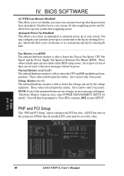
... onboard hardware monitor is able to enter SETUP". All PCI bus slots on the system use INTA#, thus all installed PCI cards must be prompted to "Press F1 to continue, DEL to detect the CPU and MB (motherboard) temperatures. These values refresh upon any of the day by selecting Everyday, which will appear: "Hardware Monitor found an error, enter POWER MANAGEMENT SETUP for details". BIOS (PnP / PCI) 48 ASUS TX97-L User's Manual NOTE: If any key...
... onboard hardware monitor is able to enter SETUP". All PCI bus slots on the system use INTA#, thus all installed PCI cards must be prompted to "Press F1 to continue, DEL to detect the CPU and MB (motherboard) temperatures. These values refresh upon any of the day by selecting Everyday, which will appear: "Hardware Monitor found an error, enter POWER MANAGEMENT SETUP for details". BIOS (PnP / PCI) 48 ASUS TX97-L User's Manual NOTE: If any key...
TX97-L User Manual
Page 49
... uses auto-routing to each PCI slot. The default setting for each function heading. BIOS SOFTWARE NOTE: SETUP Defaults are not using an ICU to accomplish this address range, you install a legacy ISA card that channel. Slot 1 (RIGHT) IRQ to its address range, select a base address from the six available options; Two options are using an ICU to use the onboard SCSI BIOS, choose Disabled. The first option, the default value, indicates either that the displayed...
... uses auto-routing to each PCI slot. The default setting for each function heading. BIOS SOFTWARE NOTE: SETUP Defaults are not using an ICU to accomplish this address range, you install a legacy ISA card that channel. Slot 1 (RIGHT) IRQ to its address range, select a base address from the six available options; Two options are using an ICU to use the onboard SCSI BIOS, choose Disabled. The first option, the default value, indicates either that the displayed...
TX97-L User Manual
Page 52
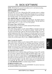
... use another IDE controller that supports four drives, you are auto-detecting a hard disk that lists LBA for connecting up to four IDE devices. Skipped entries are ignored and are not entered in the Chipset Features Setup screen. The auto-detection feature can be detected, with two connectors for an LBA drive. Remember that if you must support the Enhanced IDE features in this case); IV. The onboard PCI IDE controller supports Enhanced IDE, with parameters for that drive...
... use another IDE controller that supports four drives, you are auto-detecting a hard disk that lists LBA for connecting up to four IDE devices. Skipped entries are ignored and are not entered in the Chipset Features Setup screen. The auto-detection feature can be detected, with two connectors for an LBA drive. Remember that if you must support the Enhanced IDE features in this case); IV. The onboard PCI IDE controller supports Enhanced IDE, with parameters for that drive...


