User Guide
Page 1
R TX97-E Pentium® Motherboard USER'S MANUAL
R TX97-E Pentium® Motherboard USER'S MANUAL
User Guide
Page 4
...Chipset Features Setup 43 Power Management Setup 46 Details of the ASUS TX97-E Motherboard 11 III. INTRODUCTION 7 How this manual is organized 7 Item Checklist 7 II. INSTALLATION 12 ASUS TX97-E Motherboard Layout 12 Installation Steps 14 1. BIOS SOFTWARE 34 Support ...Menu 34 Advanced Features Menu 35 Managing & Updating your Motherboard's BIOS 36 6. FEATURES 8 Features of the ASUS TX97-E Motherboard 8 Introduction to ASUS TX97 Series of motherboards 9 Parts of Power Management Setup 46 4 ASUS TX97-E User's Manual Expansion Cards 24 Expansion Card Installation ...
...Chipset Features Setup 43 Power Management Setup 46 Details of the ASUS TX97-E Motherboard 11 III. INTRODUCTION 7 How this manual is organized 7 Item Checklist 7 II. INSTALLATION 12 ASUS TX97-E Motherboard Layout 12 Installation Steps 14 1. BIOS SOFTWARE 34 Support ...Menu 34 Advanced Features Menu 35 Managing & Updating your Motherboard's BIOS 36 6. FEATURES 8 Features of the ASUS TX97-E Motherboard 8 Introduction to ASUS TX97 Series of motherboards 9 Parts of Power Management Setup 46 4 ASUS TX97-E User's Manual Expansion Cards 24 Expansion Card Installation ...
User Guide
Page 5
... & Exit Setup 53 Exit Without Saving 53 V. SUPPORT SOFTWARE 54 ASUS TX97 Motherboard Support CD 3.02 54 LANDesk Client Manager (LDCM 54 Desktop Management Interface (DMI 56 Introducing the ASUS DMI Configuration Utility 56 System Requirements 56 Using the ASUS DMI Configuration Utility 57 VI. ASUS PCI SCSI Cards 59 Symbios SCSI BIOS and Drivers 59...
... & Exit Setup 53 Exit Without Saving 53 V. SUPPORT SOFTWARE 54 ASUS TX97 Motherboard Support CD 3.02 54 LANDesk Client Manager (LDCM 54 Desktop Management Interface (DMI 56 Introducing the ASUS DMI Configuration Utility 56 System Requirements 56 Using the ASUS DMI Configuration Utility 57 VI. ASUS PCI SCSI Cards 59 Symbios SCSI BIOS and Drivers 59...
User Guide
Page 7
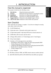
... I. Introduction: Manual information and checklist II. INTRODUCTION (Sections/Checklist) I . ASUS SCSI Cards: Installation of ASUS SCSI cards (optional) Item Checklist Please check that your retailer. (1) ASUS Motherboard (1) 9pin male serial + 25pin male serial external connector set (1) 25pin female ... User's Manual PS/2 Mouse, Infrared, USB1, and USB2 external connector module (optional) ASUS PCI-SC200 Fast-SCSI or PCI-SC860 Ultra-Fast SCSI card (optional) ASUS TX97-E User's Manual 7 Support Software: Information on the included support software VI. INTRODUCTION How ...
... I. Introduction: Manual information and checklist II. INTRODUCTION (Sections/Checklist) I . ASUS SCSI Cards: Installation of ASUS SCSI cards (optional) Item Checklist Please check that your retailer. (1) ASUS Motherboard (1) 9pin male serial + 25pin male serial external connector set (1) 25pin female ... User's Manual PS/2 Mouse, Infrared, USB1, and USB2 external connector module (optional) ASUS PCI-SC200 Fast-SCSI or PCI-SC860 Ultra-Fast SCSI card (optional) ASUS TX97-E User's Manual 7 Support Software: Information on the included support software VI. INTRODUCTION How ...
User Guide
Page 8
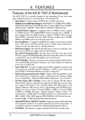
Is also equipped with two DIMM sockets to support 8-128MB 168-pin 3.3Volt SDRAM/EDO memory modules up to 256MB. This motherboard: • Intel Chipset: Features Intel's 430TX PCIset with I /O: Provides two high-speed UART compatible serial ports and one ...COM2 to the Infrared Module for the demanding PC user who wants many intelligent features in a small package. Supports two drives of the ASUS TX97-E Motherboard The ASUS TX97-E is available for an optional high-performance expansion card, which allows the use of compatibility. (Requires DMI-enabled components.) (See section V)...
Is also equipped with two DIMM sockets to support 8-128MB 168-pin 3.3Volt SDRAM/EDO memory modules up to 256MB. This motherboard: • Intel Chipset: Features Intel's 430TX PCIset with I /O: Provides two high-speed UART compatible serial ports and one ...COM2 to the Infrared Module for the demanding PC user who wants many intelligent features in a small package. Supports two drives of the ASUS TX97-E Motherboard The ASUS TX97-E is available for an optional high-performance expansion card, which allows the use of compatibility. (Requires DMI-enabled components.) (See section V)...
User Guide
Page 9
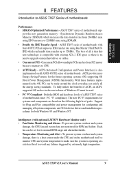
... using SDRAM. • Double the IDE Transfer Speed - Each fan can be used. • PC '97 Compliant - ASUS TX97-E User's Manual 9 ASUS TX97 series of motherboards meet PC '97 compliancy. ACPI provide more Energy Saving Features for its normal RPM range and alarm thresholds. • Temperature ...Monitoring and Alert - Both the BIOS and hardware levels of ASUS TX97 series of motherboards sup- ASUS TX97 series of motherboards. The best of all is that this new technology is compatible with existing ATA-2 IDE specs so there is...
... using SDRAM. • Double the IDE Transfer Speed - Each fan can be used. • PC '97 Compliant - ASUS TX97-E User's Manual 9 ASUS TX97 series of motherboards meet PC '97 compliancy. ACPI provide more Energy Saving Features for its normal RPM range and alarm thresholds. • Temperature ...Monitoring and Alert - Both the BIOS and hardware levels of ASUS TX97 series of motherboards sup- ASUS TX97 series of motherboards. The best of all is that this new technology is compatible with existing ATA-2 IDE specs so there is...
User Guide
Page 10
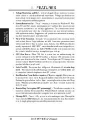
... give the user information on remotely through a modem. System voltage levels are more efficiently. • Virus Write Protection - ASUS TX97 series of two states, one of motherboards were designed to cooperate with BIOS, chipset, and flash EPROM to be in the world! • Message LED - The... stage is usually unprotected. FEATURES (TX97 Series) II. With this benefit on-hand, any user can be turned on managing their computer from anywhere in one is Sleep mode and the other is a important feature to the user. 10 ASUS TX97-E User's Manual II. Today's operating...
... give the user information on remotely through a modem. System voltage levels are more efficiently. • Virus Write Protection - ASUS TX97 series of two states, one of motherboards were designed to cooperate with BIOS, chipset, and flash EPROM to be in the world! • Message LED - The... stage is usually unprotected. FEATURES (TX97 Series) II. With this benefit on-hand, any user can be turned on managing their computer from anywhere in one is Sleep mode and the other is a important feature to the user. 10 ASUS TX97-E User's Manual II. Today's operating...
User Guide
Page 11
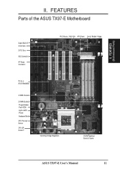
II. FEATURES Parts of the ASUS TX97-E Motherboard Super Multi-I/O 3 ISA Slots 3 PCI Slots IDE Connectors AT Power Connector PS/2 Mouse, USB, IrDA ATX Power Serial, Parallel, Floppy PCI 4 or ASUS MediaBus 4 SIMM Sockets 2 DIMM Sockets Programmable Flash ROM Intel's 430TX PCIset Hardware Monitor CPU Thermal Sensor CPU ZIF Socket 7 Switching Voltage Regulators 512KB Pipelined Burst L2 Cache ASUS TX97-E User's Manual 11 FEATURES (Motherboard Parts) II.
II. FEATURES Parts of the ASUS TX97-E Motherboard Super Multi-I/O 3 ISA Slots 3 PCI Slots IDE Connectors AT Power Connector PS/2 Mouse, USB, IrDA ATX Power Serial, Parallel, Floppy PCI 4 or ASUS MediaBus 4 SIMM Sockets 2 DIMM Sockets Programmable Flash ROM Intel's 430TX PCIset Hardware Monitor CPU Thermal Sensor CPU ZIF Socket 7 Switching Voltage Regulators 512KB Pipelined Burst L2 Cache ASUS TX97-E User's Manual 11 FEATURES (Motherboard Parts) II.
User Guide
Page 12
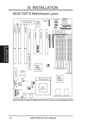
... Pipelined Burst L2 Cache NOTE: The items in outline are optional and may not be present on your motherboard version. 12 ASUS TX97-E User's Manual INSTALLATION (Motherboard Layout) MediaBus Extension Flash BIOS CR2032 3Volts Lithium Cell Intel PIIX4 PCIset FS2 FS1 FS0 Clock Freq BIOS ...Power LM78 Hardware Monitor IDE LED RTC Clear Freq. III. INSTALLATION ASUS TX97-E Motherboard Layout ISA Slot 2 Multi-I/O (En/Dis) ISA Slot 3 Keyboard BIOS Multi-I/O Super PS/2 Mouse, USB, IrDA Serial Ports COM 1 ...
... Pipelined Burst L2 Cache NOTE: The items in outline are optional and may not be present on your motherboard version. 12 ASUS TX97-E User's Manual INSTALLATION (Motherboard Layout) MediaBus Extension Flash BIOS CR2032 3Volts Lithium Cell Intel PIIX4 PCIset FS2 FS1 FS0 Clock Freq BIOS ...Power LM78 Hardware Monitor IDE LED RTC Clear Freq. III. INSTALLATION ASUS TX97-E Motherboard Layout ISA Slot 2 Multi-I/O (En/Dis) ISA Slot 3 Keyboard BIOS Multi-I/O Super PS/2 Mouse, USB, IrDA Serial Ports COM 1 ...
User Guide
Page 13
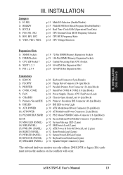
... Chassis Open Alarm Lead (4-1pin Block) p. 29 Primary / Secondary IDE Connector (40-1pin Blocks) p. 29 IDE LED Activity Light p. 30 ATX Motherboard Power Connector (20-pin Block) p. 30 AT Motherboard Power Connector (12-pin Block) p. 32 PS/2 Mouse/USB/IR Combo-Connector (18-1pin Block) p. 32 Second Infrared Port Module Connector (5-pin... uses the address 290H-297H so legacy ISA cards must not use this address or else conflicts will occur. III. INSTALLATION (Map of Board) III. ASUS TX97-E User's Manual 13
... Chassis Open Alarm Lead (4-1pin Block) p. 29 Primary / Secondary IDE Connector (40-1pin Blocks) p. 29 IDE LED Activity Light p. 30 ATX Motherboard Power Connector (20-pin Block) p. 30 AT Motherboard Power Connector (12-pin Block) p. 32 PS/2 Mouse/USB/IR Combo-Connector (18-1pin Block) p. 32 Second Infrared Port Module Connector (5-pin... uses the address 290H-297H so legacy ISA cards must not use this address or else conflicts will occur. III. INSTALLATION (Map of Board) III. ASUS TX97-E User's Manual 13
User Guide
Page 14
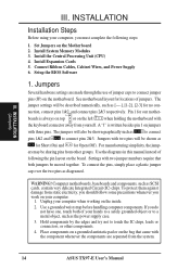
...from the system. 14 ASUS TX97-E User's Manual Use a grounded wrist strap before handling computer components. INSTALLATION Installation Steps Before using your hands to a safely grounded object or to connect jumper pins (JP) on the Motherboard 2. Set Jumpers on the motherboard. See motherboard layout for no con...- Pin 1 Pin 1 boards is written besides pin 1 on the left when holding the motherboard with two pins will also be shown as the power ...
...from the system. 14 ASUS TX97-E User's Manual Use a grounded wrist strap before handling computer components. INSTALLATION Installation Steps Before using your hands to a safely grounded object or to connect jumper pins (JP) on the Motherboard 2. Set Jumpers on the motherboard. See motherboard layout for no con...- Pin 1 Pin 1 boards is written besides pin 1 on the left when holding the motherboard with two pins will also be shown as the power ...
User Guide
Page 16
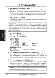
...to pins 2&3. Frequencies above jumpers CPU External (BUS) Frequency Selection. The CMOS RAM containing BIOS setup information may be stable. 16 ASUS TX97-E User's Manual Real Time Clock (RTC) RAM (RTCLR) The CMOS RAM is no power to your power supply to ensure ..., (2) Move this jumper. To clear the RTC data: (1) Turn off your computer, (5) Hold down during bootup and enter BIOS setup to your motherboard. WARNING! RTC RAM Operation Clear Data RTCLR [2-3] (Default) [1-2] (momentarily) R III. INSTALLATION 3. III. You should enter BIOS to "Load Setup...
...to pins 2&3. Frequencies above jumpers CPU External (BUS) Frequency Selection. The CMOS RAM containing BIOS setup information may be stable. 16 ASUS TX97-E User's Manual Real Time Clock (RTC) RAM (RTCLR) The CMOS RAM is no power to your power supply to ensure ..., (2) Move this jumper. To clear the RTC data: (1) Turn off your computer, (5) Hold down during bootup and enter BIOS setup to your motherboard. WARNING! RTC RAM Operation Clear Data RTCLR [2-3] (Default) [1-2] (momentarily) R III. INSTALLATION 3. III. You should enter BIOS to "Load Setup...
User Guide
Page 17
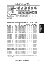
... [2-3] [1-2] 166MHz E-2.5x 66MHz [2-3] [2-3] [1-2] [----] [2-3] [2-3] *NOTE: The only IBM or Cyrix 6x86(L) (or M1) that is supported on this motherboard is revision 2.7 or later. (see next page). INSTALLATION 1 23 FS2 1 23 1 23 1 23 1 23 1 23 FS1 FS0 50MHz 55MHz 60MHz... Intel Pentium P54C Freq. 166MHz 150MHz 133MHz 120MHz 100MHz 90MHz 75MHz Ratio A-2.5x A-2.5x A-2.0x A-2.0x A-1.5x A-1.5x A-1.5x (BUS Freq.) BUS F. ASUS TX97-E User's Manual 17 FS2 FS1 FS0 66MHz [2-3] [2-3] [1-2] 60MHz [2-3] [2-3] [2-3] 66MHz [2-3] [2-3] [1-2] 60MHz [2-3] [2-3] [2-3] 66MHz [2-3] [2-3] [1-2] 60MHz ...
... [2-3] [1-2] 166MHz E-2.5x 66MHz [2-3] [2-3] [1-2] [----] [2-3] [2-3] *NOTE: The only IBM or Cyrix 6x86(L) (or M1) that is supported on this motherboard is revision 2.7 or later. (see next page). INSTALLATION 1 23 FS2 1 23 1 23 1 23 1 23 1 23 FS1 FS0 50MHz 55MHz 60MHz... Intel Pentium P54C Freq. 166MHz 150MHz 133MHz 120MHz 100MHz 90MHz 75MHz Ratio A-2.5x A-2.5x A-2.0x A-2.0x A-1.5x A-1.5x A-1.5x (BUS Freq.) BUS F. ASUS TX97-E User's Manual 17 FS2 FS1 FS0 66MHz [2-3] [2-3] [1-2] 60MHz [2-3] [2-3] [2-3] 66MHz [2-3] [2-3] [1-2] 60MHz [2-3] [2-3] [2-3] 66MHz [2-3] [2-3] [1-2] 60MHz ...
User Guide
Page 18
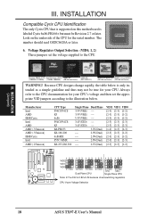
Look on this motherboard is only intended as a simple guideline and thus may not be Revision 2.7 or later. Pentium MMX (P55C) Intel Pentium (P54C) AMD-K6 AMD-K5 (150MHz-... table below . INSTALLATION Compatible Cyrix CPU Identification The only Cyrix CPU that is supported on the underside of autoswitching regulators CPU Vcore Voltage Selection 18 ASUS TX97-E User's Manual Voltage Regulator Output Selection (VID0, 1, 2) These jumpers set the appropriate VID jumpers according to the CPU documentation for your CPU's voltage and then...
Look on this motherboard is only intended as a simple guideline and thus may not be Revision 2.7 or later. Pentium MMX (P55C) Intel Pentium (P54C) AMD-K6 AMD-K5 (150MHz-... table below . INSTALLATION Compatible Cyrix CPU Identification The only Cyrix CPU that is supported on the underside of autoswitching regulators CPU Vcore Voltage Selection 18 ASUS TX97-E User's Manual Voltage Regulator Output Selection (VID0, 1, 2) These jumpers set the appropriate VID jumpers according to the CPU documentation for your CPU's voltage and then...
User Guide
Page 19
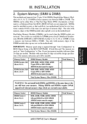
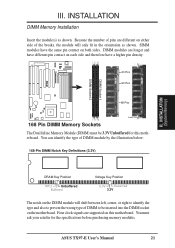
... be empty) Total System Memory (Max 256MB) Total Memory x1 x1 = ASUS TX97-E User's Manual 19 SIMMs must be installed in BIOS Chipset Setup of the SIMM module takes up one row on the motherboard. Do not use memory modules with memory chips) of the BIOS SOFTWARE. ...), or Enhanced Data Out (EDO) (BEDO & Parity are not used. INSTALLATION (System Memory) III. INSTALLATION 2. System Memory (SIMM & DIMM) This motherboard supports four 72-pin, 32-bit SIMMs (Single Inline Memory Modules) of memory chips. III. Dual Inline Memory Modules (DIMMs) can be empty) Total Memory...
... be empty) Total System Memory (Max 256MB) Total Memory x1 x1 = ASUS TX97-E User's Manual 19 SIMMs must be installed in BIOS Chipset Setup of the SIMM module takes up one row on the motherboard. Do not use memory modules with memory chips) of the BIOS SOFTWARE. ...), or Enhanced Data Out (EDO) (BEDO & Parity are not used. INSTALLATION (System Memory) III. INSTALLATION 2. System Memory (SIMM & DIMM) This motherboard supports four 72-pin, 32-bit SIMMs (Single Inline Memory Modules) of memory chips. III. Dual Inline Memory Modules (DIMMs) can be empty) Total Memory...
User Guide
Page 21
... and therefore have the same pin contact on both sides. Because the number of pins are supported on the motherboard. ASUS TX97-E User's Manual 21 You must be inserted into the DIMM socket on this motherboard. Four clock signals are different on the DIMM module will only fit in the orientation as shown. INSTALLATION... density. 20 Pins 60 Pins 88 Pins Lock 168 Pin DIMM Memory Sockets The Dual Inline Memory Module (DIMM) must ask your retailer for this motherboard.
... and therefore have the same pin contact on both sides. Because the number of pins are supported on the motherboard. ASUS TX97-E User's Manual 21 You must be inserted into the DIMM socket on this motherboard. Four clock signals are different on the DIMM module will only fit in the orientation as shown. INSTALLATION... density. 20 Pins 60 Pins 88 Pins Lock 168 Pin DIMM Memory Sockets The Dual Inline Memory Module (DIMM) must ask your retailer for this motherboard.
User Guide
Page 23
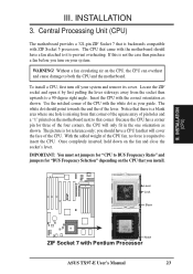
...and jumpers for reference only; Central Processing Unit (CPU) The motherboard provides a 321-pin ZIF Socket 7 that corner. To install a CPU, first turn on your system. Insert the CPU with Pentium Processor ASUS TX97-E User's Manual 23 INSTALLATION (CPU) III. Once completely inserted..., hold down on the motherboard next to that is required to both the CPU and the motherboard. III. The picture is for "BUS Frequency Selection"...
...and jumpers for reference only; Central Processing Unit (CPU) The motherboard provides a 321-pin ZIF Socket 7 that corner. To install a CPU, first turn on your system. Insert the CPU with Pentium Processor ASUS TX97-E User's Manual 23 INSTALLATION (CPU) III. Once completely inserted..., hold down on the motherboard next to that is required to both the CPU and the motherboard. III. The picture is for "BUS Frequency Selection"...
User Guide
Page 24
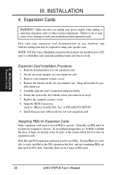
INSTALLATION 4. Failure to do so may cause severe damage to both . Remove your motherboard and expansion cards. Carefully align the card's connectors and press firmly. 6. Install the necessary software drivers for your expansion card. 2. Both ISA and PCI expansion ... system which allows the installation of a PCI card or a MediaBus card (optional multifunctional card) but most of them are two types of ISA cards. 24 ASUS TX97-E User's Manual Replace the computer system's cover. 8. Generally an IRQ must be required to use by PCI cards. Currently, there are already in PNP AND...
INSTALLATION 4. Failure to do so may cause severe damage to both . Remove your motherboard and expansion cards. Carefully align the card's connectors and press firmly. 6. Install the necessary software drivers for your expansion card. 2. Both ISA and PCI expansion ... system which allows the installation of a PCI card or a MediaBus card (optional multifunctional card) but most of them are two types of ISA cards. 24 ASUS TX97-E User's Manual Replace the computer system's cover. 8. Generally an IRQ must be required to use by PCI cards. Currently, there are already in PNP AND...
User Guide
Page 25
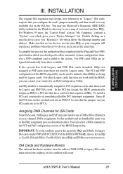
...choose Yes in "My Computer," contains a "System" icon which gives you "Resources" tab which shows the Interrupt number and address. ASUS TX97-E User's Manual 25 INSTALLATION The original ISA expansion card design, now referred to indicate which was developed to allow automatic system configuration whenever ... To simplify this process this address or else conflicts will experience problems when those available. Assigning DMA Channels for this motherboard use the same IRQs or your used by Legacy cards. ISA Cards and Hardware Monitor The onboard hardware monitor uses the...
...choose Yes in "My Computer," contains a "System" icon which gives you "Resources" tab which shows the Interrupt number and address. ASUS TX97-E User's Manual 25 INSTALLATION The original ISA expansion card design, now referred to indicate which was developed to allow automatic system configuration whenever ... To simplify this process this address or else conflicts will experience problems when those available. Assigning DMA Channels for this motherboard use the same IRQs or your used by Legacy cards. ISA Cards and Hardware Monitor The onboard hardware monitor uses the...
User Guide
Page 26
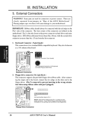
INSTALLATION 5. After connecting the single end to the floppy drive. Floppy Drive Connector 26 ASUS TX97-E User's Manual III. Placing jumper caps over these will cause damage to your 3.5inch floppy drive's light remains constantly lit, try reversing the connection to ... the side closest to the power connector on the other end to prevent inserting in "Map of the ASUS Motherboard." IDE ribbon cable must be less than 18in. (46cm), with the red stripe on the motherboard. The four corners of the connector. Some pins are labeled on the Pin 1 side of the connectors...
INSTALLATION 5. After connecting the single end to the floppy drive. Floppy Drive Connector 26 ASUS TX97-E User's Manual III. Placing jumper caps over these will cause damage to your 3.5inch floppy drive's light remains constantly lit, try reversing the connection to ... the side closest to the power connector on the other end to prevent inserting in "Map of the ASUS Motherboard." IDE ribbon cable must be less than 18in. (46cm), with the red stripe on the motherboard. The four corners of the connector. Some pins are labeled on the Pin 1 side of the connectors...


