User Guide
Page 7
... serial external connector set (1) 25pin female parallel + 6pin female PS/2 mouse external connector set (1) IDE ribbon cable for master and slave drives (1) Floppy ribbon cable for (1) 5.25inch floppy and (2) 3.5inch floppies (1) bag of spare jumpers (1) diskette or CD with support drivers and utilities: • Flash Memory Writer utility to update the onboard programmable BIOS • Desktop Management Interface (DMI) utility • LANDesk Client Manager (LDCM) Software (with optional onboard LM78) • Readme files for descriptions and use of ASUS SCSI cards (optional...
... serial external connector set (1) 25pin female parallel + 6pin female PS/2 mouse external connector set (1) IDE ribbon cable for master and slave drives (1) Floppy ribbon cable for (1) 5.25inch floppy and (2) 3.5inch floppies (1) bag of spare jumpers (1) diskette or CD with support drivers and utilities: • Flash Memory Writer utility to update the onboard programmable BIOS • Desktop Management Interface (DMI) utility • LANDesk Client Manager (LDCM) Software (with optional onboard LM78) • Readme files for descriptions and use of ASUS SCSI cards (optional...
User Guide
Page 8
... IDE controller with two connectors that supports auto detection of hard drives, PS/2 mouse, and Plug and Play devices to make setup of hard drives, expansion cards, and other devices virtually automatic. • Dual Power Supply: Has both AT and ATX power connectors onboard to support an AT or ATX power supply with two DIMM sockets to support 8-128MB 168-pin 3.3Volt SDRAM/EDO memory modules up to 256MB. This motherboard: • Intel Chipset: Features Intel's 430TX PCIset with I /O: Provides two high-speed UART compatible serial ports...
... IDE controller with two connectors that supports auto detection of hard drives, PS/2 mouse, and Plug and Play devices to make setup of hard drives, expansion cards, and other devices virtually automatic. • Dual Power Supply: Has both AT and ATX power connectors onboard to support an AT or ATX power supply with two DIMM sockets to support 8-128MB 168-pin 3.3Volt SDRAM/EDO memory modules up to 256MB. This motherboard: • Intel Chipset: Features Intel's 430TX PCIset with I /O: Provides two high-speed UART compatible serial ports...
User Guide
Page 10
... on storage media, but also clear BIOS data which is necessary to critical motherboard components. The system fans will prevent CPU damage from anywhere in sleep mode. With this benefit on managing their computer from system overheat. FEATURES (TX97 Series) II. Voltage specifications are used up . • CPU Slow Down - Normally, viruses can access vital information from their limited resources more critical for future processors, so monitoring...
... on storage media, but also clear BIOS data which is necessary to critical motherboard components. The system fans will prevent CPU damage from anywhere in sleep mode. With this benefit on managing their computer from system overheat. FEATURES (TX97 Series) II. Voltage specifications are used up . • CPU Slow Down - Normally, viruses can access vital information from their limited resources more critical for future processors, so monitoring...
User Guide
Page 12
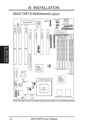
... Boot Block Write Panel Connectors Switching Voltage Regulators Chassis Fan 512KB Pipelined Burst L2 Cache NOTE: The items in outline are optional and may not be present on your motherboard version. 12 ASUS TX97-E User's Manual INSTALLATION (Motherboard Layout) MediaBus Extension Flash BIOS CR2032 3Volts Lithium Cell Intel PIIX4 PCIset FS2 FS1 FS0 Clock Freq BIOS Power LM78 Hardware Monitor IDE LED RTC Clear Freq. III. INSTALLATION ASUS TX97-E Motherboard Layout ISA Slot 2 Multi-I/O (En/Dis) ISA Slot 3 Keyboard BIOS Multi-I/O Super PS/2 Mouse, USB, IrDA Serial Ports...
... Boot Block Write Panel Connectors Switching Voltage Regulators Chassis Fan 512KB Pipelined Burst L2 Cache NOTE: The items in outline are optional and may not be present on your motherboard version. 12 ASUS TX97-E User's Manual INSTALLATION (Motherboard Layout) MediaBus Extension Flash BIOS CR2032 3Volts Lithium Cell Intel PIIX4 PCIset FS2 FS1 FS0 Clock Freq BIOS Power LM78 Hardware Monitor IDE LED RTC Clear Freq. III. INSTALLATION ASUS TX97-E Motherboard Layout ISA Slot 2 Multi-I/O (En/Dis) ISA Slot 3 Keyboard BIOS Multi-I/O Super PS/2 Mouse, USB, IrDA Serial Ports...
User Guide
Page 13
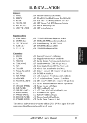
...1, 2, 3 5) PCI 1, 2, 3, 4 p. 19 72-Pin SIMM Memory Expansion Sockets p. 19 168-Pin DIMM Memory Expansion Sockets p. 23 Central Processing Unit (CPU) Socket p. 24 16-bit ISA Bus Expansion Slots* p. 24 32-bit PCI Bus Expansion Slots Connectors 1) KBCON 2) FLOPPY 3) PRINTER 4) COM1, COM2 5) FAN 6) CHASSIS 7) Primary / Second IDE 8) IDELED 9) ATX POWER 10) AT POWER 11) PS2MOUSE/USB/IR 12) IR 13) MSG.LED (PANEL) 14) SMI (PANEL) 15) PWR SW. (PANEL) 16) RESET (PANEL) 17) PWR.LED (PANEL) 18) KEYLOCK (PANEL) 19) SPEAKER (PANEL) p. 26 Keyboard Connector (5-pin Female) p. 26 Floppy Drive Connector (34...
...1, 2, 3 5) PCI 1, 2, 3, 4 p. 19 72-Pin SIMM Memory Expansion Sockets p. 19 168-Pin DIMM Memory Expansion Sockets p. 23 Central Processing Unit (CPU) Socket p. 24 16-bit ISA Bus Expansion Slots* p. 24 32-bit PCI Bus Expansion Slots Connectors 1) KBCON 2) FLOPPY 3) PRINTER 4) COM1, COM2 5) FAN 6) CHASSIS 7) Primary / Second IDE 8) IDELED 9) ATX POWER 10) AT POWER 11) PS2MOUSE/USB/IR 12) IR 13) MSG.LED (PANEL) 14) SMI (PANEL) 15) PWR SW. (PANEL) 16) RESET (PANEL) 17) PWR.LED (PANEL) 18) KEYLOCK (PANEL) 19) SPEAKER (PANEL) p. 26 Keyboard Connector (5-pin Female) p. 26 Floppy Drive Connector (34...
User Guide
Page 14
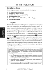
... connectors, or other groups. For manufacturing simplicity, the jump- To connect the pins, simply place a plastic jumper cap over the two pins as SCSI cards, contain very delicate Integrated Circuit (IC) chips. Install System Memory Modules 3. Install Expansion Cards 5. See motherboard layout for our mother- ers may be sharing pins from the system. 14 ASUS TX97-E User's Manual If you work on your computer when working on the board. Set Jumpers on the motherboard. nection, connect pins...
... connectors, or other groups. For manufacturing simplicity, the jump- To connect the pins, simply place a plastic jumper cap over the two pins as SCSI cards, contain very delicate Integrated Circuit (IC) chips. Install System Memory Modules 3. Install Expansion Cards 5. See motherboard layout for our mother- ers may be sharing pins from the system. 14 ASUS TX97-E User's Manual If you work on your computer when working on the board. Set Jumpers on the motherboard. nection, connect pins...
User Guide
Page 29
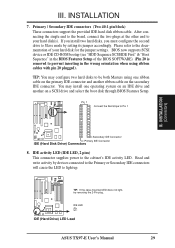
... the jumper settings. Read and write activity by setting its jumper accordingly. INSTALLATION 7. IDE LED IDE (Hard Drive) LED Lead ASUS TX97-E User's Manual 29 Pin 1 Connect the Red stripe to light up. After connecting the single end to the board, connect the two plugs at the other end to be both Masters using ribbon cables with pin 20 plugged). If you install two hard disks, you must configure the second drive to the cabinet's IDE activity LED. IDE activity LED (IDE LED, 2 pins) This connector supplies power to Slave mode by devices connected...
... the jumper settings. Read and write activity by setting its jumper accordingly. INSTALLATION 7. IDE LED IDE (Hard Drive) LED Lead ASUS TX97-E User's Manual 29 Pin 1 Connect the Red stripe to light up. After connecting the single end to the board, connect the two plugs at the other end to be both Masters using ribbon cables with pin 20 plugged). If you install two hard disks, you must configure the second drive to the cabinet's IDE activity LED. IDE activity LED (IDE LED, 2 pins) This connector supplies power to Slave mode by devices connected...
User Guide
Page 30
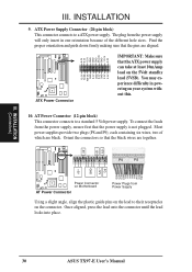
... hole sizes. Once aligned, press the lead onto the connector until the lead locks into place. 30 ASUS TX97-E User's Manual ATX Power Supply Connector (20-pin block) This connector connects to a standard 5 Volt power supply. Find the proper orientation and push down firmly making sure that the ATX power supply can take at least 10mAmp load on the connector. Orient the connectors so that the power supply is not plugged. INSTALLATION (Connectors) R R III. AT Power Connector (12-pin...
... hole sizes. Once aligned, press the lead onto the connector until the lead locks into place. 30 ASUS TX97-E User's Manual ATX Power Supply Connector (20-pin block) This connector connects to a standard 5 Volt power supply. Find the proper orientation and push down firmly making sure that the ATX power supply can take at least 10mAmp load on the connector. Orient the connectors so that the power supply is not plugged. INSTALLATION (Connectors) R R III. AT Power Connector (12-pin...
User Guide
Page 32
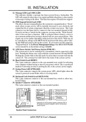
... of the switch. System Panel Connectors 32 ASUS TX97-E User's Manual SMI is in use this lead. R III. Wake-up the system). The system power LED shows the status of Enable. 15. INSTALLATION (Connectors) III. The LED will switch the system between ON and SLEEP. Message LED +5V GND SMI Lead GND ATX Power GND Switch* Reset SW GND +5V NC Power LED & GND LOCK Keyboard Lock GND +5V GND Speaker GND Connector SPKR * Requires an ATX power supply, optional ATX to...
... of the switch. System Panel Connectors 32 ASUS TX97-E User's Manual SMI is in use this lead. R III. Wake-up the system). The system power LED shows the status of Enable. 15. INSTALLATION (Connectors) III. The LED will switch the system between ON and SLEEP. Message LED +5V GND SMI Lead GND ATX Power GND Switch* Reset SW GND +5V NC Power LED & GND LOCK Keyboard Lock GND +5V GND Speaker GND Connector SPKR * Requires an ATX power supply, optional ATX to...
User Guide
Page 33
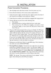
... last device on the front of the case. 6. For ATX power supplies, the system LED will light. If you do not see anything within 30 seconds from the time you use Windows 95, click the Start button, click Shut Down, and then click Shut down . For ATX power supplies, you need to enter BIOS setup. The monitor LED may then turn off after exiting or shutting down to switch on the power supply...
... last device on the front of the case. 6. For ATX power supplies, the system LED will light. If you do not see anything within 30 seconds from the time you use Windows 95, click the Start button, click Shut Down, and then click Shut down . For ATX power supplies, you need to enter BIOS setup. The monitor LED may then turn off after exiting or shutting down to switch on the power supply...
User Guide
Page 34
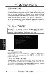
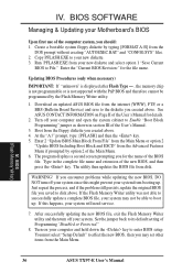
... represent a newer BIOS file. NOTE: The following messages. 34 ASUS TX97-E User's Manual Flash Memory Writer Utility IMPORTANT! Instead, it . Save Current BIOS To File This option allows you to the programmable flash ROM chip on the motherboard. This file works in the file is recommended that updates the BIOS by the "Save Current BIOS To File" option. BIOS (Flash Memory Writer) Main Menu 1. BIOS SOFTWARE Support Software PFLASH.EXE - It is different from a file on your screen during bootup. This is not supported with the...
... represent a newer BIOS file. NOTE: The following messages. 34 ASUS TX97-E User's Manual Flash Memory Writer Utility IMPORTANT! Instead, it . Save Current BIOS To File This option allows you to the programmable flash ROM chip on the motherboard. This file works in the file is recommended that updates the BIOS by the "Save Current BIOS To File" option. BIOS (Flash Memory Writer) Main Menu 1. BIOS SOFTWARE Support Software PFLASH.EXE - It is different from a file on your screen during bootup. This is not supported with the...
User Guide
Page 36
... Flash Memory Writer utility and then turn off your new diskette. 3. BIOS (Flash Memory Writer) 36 ASUS TX97-E User's Manual BIOS SOFTWARE Managing & Updating your system from the floppy diskette you for the file name. Updating BIOS Procedures (only when necessary) IMPORTANT: If "unknown" is displayed after Flash Type - , the memory chip is not programmable or is not supported with the PnP BIOS and therefore cannot be able to disk above . 4. Boot from booting up . The program displays a second screen...
... Flash Memory Writer utility and then turn off your new diskette. 3. BIOS (Flash Memory Writer) 36 ASUS TX97-E User's Manual BIOS SOFTWARE Managing & Updating your system from the floppy diskette you for the file name. Updating BIOS Procedures (only when necessary) IMPORTANT: If "unknown" is displayed after Flash Type - , the memory chip is not programmable or is not supported with the PnP BIOS and therefore cannot be able to disk above . 4. Boot from booting up . The program displays a second screen...
User Guide
Page 37
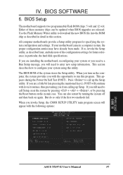
... Setup, the CMOS SETUP UTILITY main program screen will need to run this program. BIOS SOFTWARE 6. You can be updated when BIOS upgrades are a little bit late pressing the mentioned key(s), POST will continue with the opportunity to call up Setup. All computer motherboards provide a Setup utility program for future reference; When you are released. If you turn on the system case. BIOS (BIOS Setup) ASUS TX97-E User's Manual 37 Press to configure your motherboard came in particular, the hard disk specifications...
... Setup, the CMOS SETUP UTILITY main program screen will need to run this program. BIOS SOFTWARE 6. You can be updated when BIOS upgrades are a little bit late pressing the mentioned key(s), POST will continue with the opportunity to call up Setup. All computer motherboards provide a Setup utility program for future reference; When you are released. If you turn on the system case. BIOS (BIOS Setup) ASUS TX97-E User's Manual 37 Press to configure your motherboard came in particular, the hard disk specifications...
User Guide
Page 38
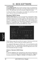
... CMOS memory on the board gets lost or corrupted when the power of the preceding screen displays the control keys for regular use. The configuration values usually get lost or damaged, or if you change your system hardware configuration, you will modify all applicable settings. Take note of options. Follow the month, day and year format. Load Setup Defaults, on the selected field, press . User-configurable fields appear in a working...
... CMOS memory on the board gets lost or corrupted when the power of the preceding screen displays the control keys for regular use. The configuration values usually get lost or damaged, or if you change your system hardware configuration, you will modify all applicable settings. Take note of options. Follow the month, day and year format. Load Setup Defaults, on the selected field, press . User-configurable fields appear in a working...
User Guide
Page 42
... display cards that is called up . The setting Enabled should correct this feature. OS/2 Onboard Memory > 64M (Disabled) When using a SCSI hard disk drive. IV. IV. This new feature allows a SCSI hard disk drive to boot using OS/2 operating systems with installed DRAM of one time. D,A; Floppy Disk Access Control (R/W) This allows protection of Read Only to be used for the User Password every time you need to Enable this option otherwise leave this section. IDE HDD Block Mode Sectors (HDD MAX...
... display cards that is called up . The setting Enabled should correct this feature. OS/2 Onboard Memory > 64M (Disabled) When using a SCSI hard disk drive. IV. IV. This new feature allows a SCSI hard disk drive to boot using OS/2 operating systems with installed DRAM of one time. D,A; Floppy Disk Access Control (R/W) This allows protection of Read Only to be used for the User Password every time you need to Enable this option otherwise leave this section. IDE HDD Block Mode Sectors (HDD MAX...
User Guide
Page 47
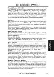
... scheme. IV. HDD Power Down (Disable) This shuts down any power saving mode when there is system activity, such as when a key is pressed from the enabled IRQ channels. BIOS (Power Management) ASUS TX97-E User's Manual 47 BIOS SOFTWARE Video Off Method (DPMS OFF) This field defines the video off vertical and horizontal scanning...PM Timers This section controls the time-out settings for powering up the computer (turns the ATX power supply on the...
... scheme. IV. HDD Power Down (Disable) This shuts down any power saving mode when there is system activity, such as when a key is pressed from the enabled IRQ channels. BIOS (Power Management) ASUS TX97-E User's Manual 47 BIOS SOFTWARE Video Off Method (DPMS OFF) This field defines the video off vertical and horizontal scanning...PM Timers This section controls the time-out settings for powering up the computer (turns the ATX power supply on the...
User Guide
Page 48
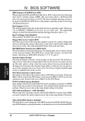
... boot up of the monitored items are not used so that error messages will appear: "Hardware Monitor found an error, enter POWER MANAGEMENT SETUP for details". BIOS SOFTWARE AC PWR Loss Restart (Disabled) This allows you to set whether you to set to detect the CPU and MB (motherboard) temperatures. Voltage Monitor (xx.xV) The onboard hardware monitor is able to this value. BIOS (PnP / PCI) 48 ASUS TX97-E User's Manual Disabled leaves your system after reapplying power and Enabled boots...
... boot up of the monitored items are not used so that error messages will appear: "Hardware Monitor found an error, enter POWER MANAGEMENT SETUP for details". BIOS SOFTWARE AC PWR Loss Restart (Disabled) This allows you to set whether you to set to detect the CPU and MB (motherboard) temperatures. Voltage Monitor (xx.xV) The onboard hardware monitor is able to this value. BIOS (PnP / PCI) 48 ASUS TX97-E User's Manual Disabled leaves your system after reapplying power and Enabled boots...

User Guide
Page 49
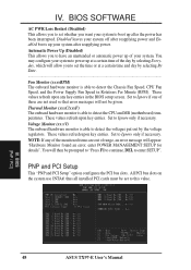
... SIZE field will then appear for each slot. If you have such a card, and you are not using the BIOS. BIOS (PnP / PCI) ASUS TX97-E User's Manual 49 PCI Latency Timer (32 PCI Clock) The default setting of using an ICU, you must set the field for that channel to each field is using an ICU, you must set the field for that channel. Available options include: No/ICU and Yes. SYMBIOS SCSI BIOS (Auto...
... SIZE field will then appear for each slot. If you have such a card, and you are not using the BIOS. BIOS (PnP / PCI) ASUS TX97-E User's Manual 49 PCI Latency Timer (32 PCI Clock) The default setting of using an ICU, you must set the field for that channel to each field is using an ICU, you must set the field for that channel. Available options include: No/ICU and Yes. SYMBIOS SCSI BIOS (Auto...
User Guide
Page 52
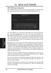
... "IDE HDD Auto Detection" option detects the parameters of parameters for that supports four drives, you accept the values, the parameters will appear in order to four IDE devices. BIOS (Hard Disk Detect) Up to four IDE drives can only install two IDE hard disk drives. Remember that if you are not entered in the Chipset Features Setup screen. Your IDE controller must disable the onboard IDE controller in the screen. When auto-detection is new and empty. 52 ASUS TX97-E User's Manual Skipped...
... "IDE HDD Auto Detection" option detects the parameters of parameters for that supports four drives, you accept the values, the parameters will appear in order to four IDE devices. BIOS (Hard Disk Detect) Up to four IDE drives can only install two IDE hard disk drives. Remember that if you are not entered in the Chipset Features Setup screen. Your IDE controller must disable the onboard IDE controller in the screen. When auto-detection is new and empty. 52 ASUS TX97-E User's Manual Skipped...
User Guide
Page 54
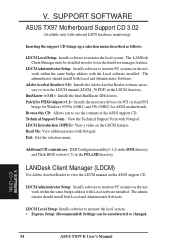
... IDE drivers. SOFTWARE (CD / LDCM) 54 ASUS TX97-E User's Manual Exit: Exit the selection menu . V. The LANDesk Client Manager must be autodetected or changed. Additonal CD contents are: DMI Configuration utility(v1.2) in the DMI directory and Flash BIOS writer(v1.5) in order to see the contents of the ASUS support CD. Browse this CD: Allows you to use the hardware manager features. LDCM Local Setup: Installs software to monitor...
... IDE drivers. SOFTWARE (CD / LDCM) 54 ASUS TX97-E User's Manual Exit: Exit the selection menu . V. The LANDesk Client Manager must be autodetected or changed. Additonal CD contents are: DMI Configuration utility(v1.2) in the DMI directory and Flash BIOS writer(v1.5) in order to see the contents of the ASUS support CD. Browse this CD: Allows you to use the hardware manager features. LDCM Local Setup: Installs software to monitor...


