User Manual
Page 4
...options 3.1 Preparing the system for rack mounting 3-2 3.2 Attaching the inner rail to the server 3-2 3.3 Attaching the rails to the rack 3-3 3.4 Mounting the server to the rack 3-4 Chapter 4: Motherboard Info 4.1 Motherboard layout 4-2 4.2 Jumpers 4-4 ...4.3 Internal connectors 4-9 4.4 Internal LEDs 4-17 Chapter 5: BIOS setup 5.1 Managing and updating your BIOS 5-2 5.1.1 ASUS EZ Flash 2 utility 5-2 5.1.2 BUPDATER utility 5-3 5.1.3 ASUS CrashFree BIOS 3 utility ...
...options 3.1 Preparing the system for rack mounting 3-2 3.2 Attaching the inner rail to the server 3-2 3.3 Attaching the rails to the rack 3-3 3.4 Mounting the server to the rack 3-4 Chapter 4: Motherboard Info 4.1 Motherboard layout 4-2 4.2 Jumpers 4-4 ...4.3 Internal connectors 4-9 4.4 Internal LEDs 4-17 Chapter 5: BIOS setup 5.1 Managing and updating your BIOS 5-2 5.1.1 ASUS EZ Flash 2 utility 5-2 5.1.2 BUPDATER utility 5-3 5.1.3 ASUS CrashFree BIOS 3 utility ...
User Manual
Page 5
... 5-18 5.4.3 Onboard Devices Configuration 5-20 5.4.4 USB Configuration 5-21 5.4.5 PCIPnP 5-22 5.4.6 ACPI Configuration 5-23 5.4.7 Event Log Configuration 5-25 5.4.8 Intel VT-d Configuration 5-25 5.4.9 SR-IOV Supprted 5-25 5.5 Server menu 5-26 5.6 Power menu 5-28 5.6.1 ACPI APIC Support 5-28 5.6.2 APM Configuration 5-28 5.6.3 Hardware Monitor 5-30 5.7 Boot menu 5-31 5.7.1 Boot Device Priority 5-31 5.7.2 Boot Settings Configuration...
... 5-18 5.4.3 Onboard Devices Configuration 5-20 5.4.4 USB Configuration 5-21 5.4.5 PCIPnP 5-22 5.4.6 ACPI Configuration 5-23 5.4.7 Event Log Configuration 5-25 5.4.8 Intel VT-d Configuration 5-25 5.4.9 SR-IOV Supprted 5-25 5.5 Server menu 5-26 5.6 Power menu 5-28 5.6.1 ACPI APIC Support 5-28 5.6.2 APM Configuration 5-28 5.6.3 Hardware Monitor 5-30 5.7 Boot menu 5-31 5.7.1 Boot Device Priority 5-31 5.7.2 Boot Settings Configuration...
User Manual
Page 8
...a stable surface. Danger of this product or units is to be performed by trained service personnel only. • Before operating the server, carefully read all the manuals included with a three-wire power cable and plug for the user's safety. If possible, disconnect all...existing system before you service. • If the power supply is incorrectly replaced. This product is heavy. This server system is equipped with the server package. • Before using the server, make sure all power cables from the system, contact a qualified service technician or your dealer. viii CD-...
...a stable surface. Danger of this product or units is to be performed by trained service personnel only. • Before operating the server, carefully read all the manuals included with a three-wire power cable and plug for the user's safety. If possible, disconnect all...existing system before you service. • If the power supply is incorrectly replaced. This product is heavy. This server system is equipped with the server package. • Before using the server, make sure all power cables from the system, contact a qualified service technician or your dealer. viii CD-...
User Manual
Page 9
... the following parts: 1. Chapter 5: BIOS information This chapter tells how to install the optional components and devices into the barebone server. 4. DO NOT throw the motherboard in municipal waste. This symbol of the crossed out wheeled bin indicates that you have to... should not be placed in municipal waste. Chapter 4: Motherboard information This chapter includes the motherboard layout and brief descriptions of the server, including sections on front panel and rear panel specifications. 2. Chapter 3: Installation options This chapter describes how to change system settings...
... the following parts: 1. Chapter 5: BIOS information This chapter tells how to install the optional components and devices into the barebone server. 4. DO NOT throw the motherboard in municipal waste. This symbol of the crossed out wheeled bin indicates that you have to... should not be placed in municipal waste. Chapter 4: Motherboard information This chapter includes the motherboard layout and brief descriptions of the server, including sections on front panel and rear panel specifications. 2. Chapter 3: Installation options This chapter describes how to change system settings...
User Manual
Page 10
...a word or a phrase. CAUTION: Information to prevent damage to the components when trying to set up and use the proprietary ASUS server management utility. 2. Keys enclosed in brackets. If you must press two or more keys simultaneously, the key names are linked with a plus ...sign (+). ASUS Server Web-based Management (ASWM) user guide This manual tells how to complete a task. Refer to complete a task. Conventions To make sure...
...a word or a phrase. CAUTION: Information to prevent damage to the components when trying to set up and use the proprietary ASUS server management utility. 2. Keys enclosed in brackets. If you must press two or more keys simultaneously, the key names are linked with a plus ...sign (+). ASUS Server Web-based Management (ASWM) user guide This manual tells how to complete a task. Refer to complete a task. Conventions To make sure...
User Manual
Page 11
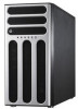
Product introduction Chapter 1 This chapter describes the general features of the server, including sections on front panel and rear panel specifications. ASUS TS300-E6/PS4
Product introduction Chapter 1 This chapter describes the general features of the server, including sections on front panel and rear panel specifications. ASUS TS300-E6/PS4
User Manual
Page 12
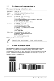
... take note of the above items is damaged or missing, contact your problems. TS300-E6/PS4 xxS0xxxxxxxxxx 1-2 Chapter 1: Product introduction 1.1 System package contents Check your system package for the following items. Model Name TS300-E6/PS4 Chassis ASUS T50A Pedestal 5U Rackmount Chassis Motherboard ASUS P7F-E Server Board Component 1 x 390W 80+ Single Power Supply 4 x hot-swap HDD trays 1 x SAS...
... take note of the above items is damaged or missing, contact your problems. TS300-E6/PS4 xxS0xxxxxxxxxx 1-2 Chapter 1: Product introduction 1.1 System package contents Check your system package for the following items. Model Name TS300-E6/PS4 Chassis ASUS T50A Pedestal 5U Rackmount Chassis Motherboard ASUS P7F-E Server Board Component 1 x 390W 80+ Single Power Supply 4 x hot-swap HDD trays 1 x SAS...
User Manual
Page 13
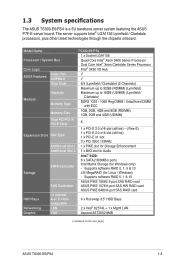
... LAN Graphic VGA Aspeed AST2050 8MB (continued on the next page) ASUS TS300-E6/PS4 1-3 The server supports Intel® LGA1156 Lynnfield / Clarkdale processors, plus other latest technologies through the chipsets onboard. 1.3 System specifications The ASUS TS300-E6/PS4 is a 5U barebone server system featuring the ASUS P7F-E server board. Supports software RAID 0, 1 & 10 ASUS PIKE 1064E 4-port SAS RAID card SAS Controller...
... LAN Graphic VGA Aspeed AST2050 8MB (continued on the next page) ASUS TS300-E6/PS4 1-3 The server supports Intel® LGA1156 Lynnfield / Clarkdale processors, plus other latest technologies through the chipsets onboard. 1.3 System specifications The ASUS TS300-E6/PS4 is a 5U barebone server system featuring the ASUS P7F-E server board. Supports software RAID 0, 1 & 10 ASUS PIKE 1064E 4-port SAS RAID card SAS Controller...

User Manual
Page 14
... ~ 90% ( Non- condensing) *Specifications are subject to change without any notice) Optional anti-virus CD Pack Optional ASMB4-iKVM for KVM-over-IP support ASUS ASWM 2.0® 445mm x 217.5mm x 545mm 20 Kg 390W (80+) Single Power Supply Input: 100-240Vac, 6-3A, 50-60Hz, Class I /O... Port 3 x RJ-45 ports (1 for ASMB4-iKVM) 4 x USB 2.0 ports (Front x 2, Rear x 2) 1 x VGA port 1 x PS/2 keyboard port 1 x PS/2 mouse port Windows® Server 2008 Enterprise 32 / 64-bit Windows® Server 2003 R2 Enterprise 32 / 64-bit RedHat® Enterprise Linux AS5.0 32 / 64-bit SuSE® Linux Enterprise...
... ~ 90% ( Non- condensing) *Specifications are subject to change without any notice) Optional anti-virus CD Pack Optional ASMB4-iKVM for KVM-over-IP support ASUS ASWM 2.0® 445mm x 217.5mm x 545mm 20 Kg 390W (80+) Single Power Supply Input: 100-240Vac, 6-3A, 50-60Hz, Class I /O... Port 3 x RJ-45 ports (1 for ASMB4-iKVM) 4 x USB 2.0 ports (Front x 2, Rear x 2) 1 x VGA port 1 x PS/2 keyboard port 1 x PS/2 mouse port Windows® Server 2008 Enterprise 32 / 64-bit Windows® Server 2003 R2 Enterprise 32 / 64-bit RedHat® Enterprise Linux AS5.0 32 / 64-bit SuSE® Linux Enterprise...
User Manual
Page 15
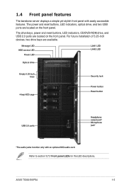
For future installation of 5.25-inch devices, two drive bays are located on the front panel. ASUS TS300-E6/PS4 1-5 The drive bays, power and reset buttons, LED indicators, CD/DVD-ROM drive, and USB 2.0 ports are available. Refer to section 1.7.1 Front panel... Reset button USB 2.0 ports Headphone output jack* Microphone jack* *The audio jacks function only with easily accessible features. 1.4 Front panel features The barebone server displays a simple yet stylish front panel with an optional MIO audio card. The power and reset buttons, LED indicators, optical drive, and two USB...
For future installation of 5.25-inch devices, two drive bays are located on the front panel. ASUS TS300-E6/PS4 1-5 The drive bays, power and reset buttons, LED indicators, CD/DVD-ROM drive, and USB 2.0 ports are available. Refer to section 1.7.1 Front panel... Reset button USB 2.0 ports Headphone output jack* Microphone jack* *The audio jacks function only with easily accessible features. 1.4 Front panel features The barebone server displays a simple yet stylish front panel with an optional MIO audio card. The power and reset buttons, LED indicators, optical drive, and two USB...
User Manual
Page 17
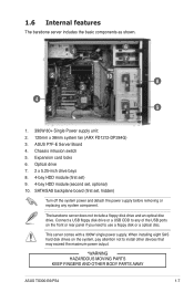
... to install other devices that may exceed the maximum power output. *WARNING HAZARDOUS MOVING PARTS KEEP FINGERS AND OTHER BODY PARTS AWAY ASUS TS300-E6/PS4 1-7 ASUS P7F-E Server Board 4. 1.6 Internal features The barebone server includes the basic components as shown. 1 6 7 2 10 8 3 4 5 9 1. 390W 80+ Single Power supply unit: 2. 120mm x 38mm system fan (ARX FD1212-DP284G) 3. Chassis intrusion...
... to install other devices that may exceed the maximum power output. *WARNING HAZARDOUS MOVING PARTS KEEP FINGERS AND OTHER BODY PARTS AWAY ASUS TS300-E6/PS4 1-7 ASUS P7F-E Server Board 4. 1.6 Internal features The barebone server includes the basic components as shown. 1 6 7 2 10 8 3 4 5 9 1. 390W 80+ Single Power supply unit: 2. 120mm x 38mm system fan (ARX FD1212-DP284G) 3. Chassis intrusion...
User Manual
Page 22
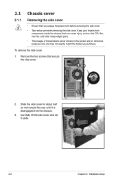
... inside the chassis that can cause injury, such as the CPU fan, rear fan, and other sharp-edged parts. • The images of the barebone server shown in this section are for about half an inch toward the rear until it aside. 1 2 2-2 Chapter 2: Hardware setup To remove the side cover 1. Slide...
... inside the chassis that can cause injury, such as the CPU fan, rear fan, and other sharp-edged parts. • The images of the barebone server shown in this section are for about half an inch toward the rear until it aside. 1 2 2-2 Chapter 2: Hardware setup To remove the side cover 1. Slide...
User Manual
Page 34
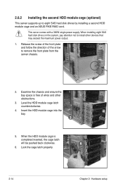
... HDD module cage is free of the arrow to eight SAS hard disk drives by installing a second HDD module cage and an ASUS PIKE RAID card. 2.6.2 Installing the second HDD module cage (optional) This server supports up to remove the front plate from the server chassis. 2. This server comes with a 390W single power supply.
... HDD module cage is free of the arrow to eight SAS hard disk drives by installing a second HDD module cage and an ASUS PIKE RAID card. 2.6.2 Installing the second HDD module cage (optional) This server supports up to remove the front plate from the server chassis. 2. This server comes with a 390W single power supply.
User Manual
Page 42
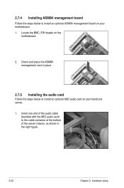
2.7.4 Installing ASMB4 management board Follow the steps below to install an optional ASMB4 management board on the motherboard. 2. Insert one end of the audio cable (bundled with the MIO audio card) to the cable container at the bottom of the server chassis, as shown in place. 2.7.5 Installing the audio card Follow the steps below to install an optional MIO audio card on your motherboard. 1. Locate the BMC_FW header on your barebone server. 1. Orient and press the ASMB4 management card in the right figure. 2-22 Chapter 2: Hardware setup
2.7.4 Installing ASMB4 management board Follow the steps below to install an optional ASMB4 management board on the motherboard. 2. Insert one end of the audio cable (bundled with the MIO audio card) to the cable container at the bottom of the server chassis, as shown in place. 2.7.5 Installing the audio card Follow the steps below to install an optional MIO audio card on your motherboard. 1. Locate the BMC_FW header on your barebone server. 1. Orient and press the ASMB4 management card in the right figure. 2-22 Chapter 2: Hardware setup

User Manual
Page 49
... for stability. Repeat step 1 and 2 to reinstall the rear system fan. 2.9.2 Chassis footpads The barebone server system is shipped with a Philips (cross) screwdriver. 3. Follow the previous instructions in reverse to remove the other three footpads. ASUS TS300-E6/PS4 2-29 Carefully �ta�k��e��o�ff��th��...
... for stability. Repeat step 1 and 2 to reinstall the rear system fan. 2.9.2 Chassis footpads The barebone server system is shipped with a Philips (cross) screwdriver. 3. Follow the previous instructions in reverse to remove the other three footpads. ASUS TS300-E6/PS4 2-29 Carefully �ta�k��e��o�ff��th��...
User Manual
Page 51
ASUS TS300-E6/PS4 Installation options Chapter 3 This chapter describes how to install the optional components and devices into the barebone server.
ASUS TS300-E6/PS4 Installation options Chapter 3 This chapter describes how to install the optional components and devices into the barebone server.

User Manual
Page 52
...chassis with screws. 3. Align the screw holes on removing the footpads. Repeat the previous steps to secure the other inner rail to the server 1. Removing the top cover Unscrew and slide the top cover toward the rear panel, and then lift it up from the rackmount rail... footpads for the optional configurations described in this chapter are purchased separately. • We recommend that you allot at least 1U space above the server system to the chassis top with screws. 3-2 Chapter 3: Installation options 3.1 Preparing the system for rack mounting • The items required for ...
...chassis with screws. 3. Align the screw holes on removing the footpads. Repeat the previous steps to secure the other inner rail to the server 1. Removing the top cover Unscrew and slide the top cover toward the rear panel, and then lift it up from the rackmount rail... footpads for the optional configurations described in this chapter are purchased separately. • We recommend that you allot at least 1U space above the server system to the chassis top with screws. 3-2 Chapter 3: Installation options 3.1 Preparing the system for rack mounting • The items required for ...
User Manual
Page 53
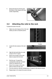
Align the front end holes of a rack rail pair to install the server. 2. Select one unit of the chassis with three screws respectively. 3.3 Attaching the rails to the rack To attach the rails to secure the rear end. 7. ... and the bottom of space (1U) on the outer holes to secure the front end. 5. Drive in two screws on the rack rails. 1U space 3. ASUS TS300-E6/PS4 3-3 4.
Align the front end holes of a rack rail pair to install the server. 2. Select one unit of the chassis with three screws respectively. 3.3 Attaching the rails to the rack To attach the rails to secure the rear end. 7. ... and the bottom of space (1U) on the outer holes to secure the front end. 5. Drive in two screws on the rack rails. 1U space 3. ASUS TS300-E6/PS4 3-3 4.
User Manual
Page 54
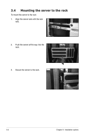
Align the server rails with the rack rails. 2. Push the server all the way into the rack. 3. 3.4 Mounting the server to the rack To mount the server to the rack. 3-4 Chapter 3: Installation options Secure the server to the rack 1.
Align the server rails with the rack rails. 2. Push the server all the way into the rack. 3. 3.4 Mounting the server to the rack To mount the server to the rack. 3-4 Chapter 3: Installation options Secure the server to the rack 1.
User Manual
Page 67
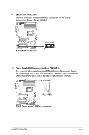
Power Supply SMBus connector (5-pin PSUSMB1) This connector allows you to connect SMBus (System Management Bus) to the power supply unit to read PSU information. BMC header (BMC_FW1) The BMC connector on the motherboard supports an ASUS® Server Management Board 4 Series (ASMB4). 10. Devices communicate with an SMBus host and/or other SMBus devices using the SMBus interface. ASUS TS300-E6/PS4 4-13 9.
Power Supply SMBus connector (5-pin PSUSMB1) This connector allows you to connect SMBus (System Management Bus) to the power supply unit to read PSU information. BMC header (BMC_FW1) The BMC connector on the motherboard supports an ASUS® Server Management Board 4 Series (ASMB4). 10. Devices communicate with an SMBus host and/or other SMBus devices using the SMBus interface. ASUS TS300-E6/PS4 4-13 9.
