User Manual
Page 6
...Installing hard disk drives 6-2 6.1.3 RAID controller selection 6-3 6.1.4 Setting the RAID item in BIOS 6-3 6.2 LSI Software RAID Configuration Utility 6-4 6.2.1 Creating a RAID set 6-5 6.2.2 Adding or viewing a RAID configuration 6-11 6.2.3 Initializing the virtual drives 6-12 6.2.4 Rebuilding failed drives 6-16 6.2.5 Checking the drives for data consistency 6-18 6.2.6 Deleting a RAID configuration 6-21 6.2.7 Selecting the boot drive from a RAID set 6-22 6.2.8 Enabling WriteCache 6-23 6.3 Intel® Matrix Storage Manager Option ROM Utility 6-24 6.3.1 Creating a RAID...
...Installing hard disk drives 6-2 6.1.3 RAID controller selection 6-3 6.1.4 Setting the RAID item in BIOS 6-3 6.2 LSI Software RAID Configuration Utility 6-4 6.2.1 Creating a RAID set 6-5 6.2.2 Adding or viewing a RAID configuration 6-11 6.2.3 Initializing the virtual drives 6-12 6.2.4 Rebuilding failed drives 6-16 6.2.5 Checking the drives for data consistency 6-18 6.2.6 Deleting a RAID configuration 6-21 6.2.7 Selecting the boot drive from a RAID set 6-22 6.2.8 Enabling WriteCache 6-23 6.3 Intel® Matrix Storage Manager Option ROM Utility 6-24 6.3.1 Creating a RAID...
User Manual
Page 9
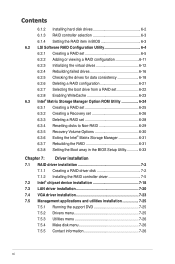
... products. Chapter 2: Hardware setup This chapter lists the hardware setup procedures that you have to enable proper reuse of the crossed out wheeled bin indicates that the battery should not be placed in municipal waste. Chapter 6: RAID configuration This chapter provides instructions for setting up, creating and configuring RAID sets using the available utilities. 7 Chapter 7: Driver installation This chapter provides instructions for installing the necessary drivers for disposal of configuring a server. Check local regulations...
... products. Chapter 2: Hardware setup This chapter lists the hardware setup procedures that you have to enable proper reuse of the crossed out wheeled bin indicates that the battery should not be placed in municipal waste. Chapter 6: RAID configuration This chapter provides instructions for setting up, creating and configuring RAID sets using the available utilities. 7 Chapter 7: Driver installation This chapter provides instructions for installing the necessary drivers for disposal of configuring a server. Check local regulations...
User Manual
Page 17
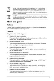
... install other devices that may exceed the maximum power output. *WARNING HAZARDOUS MOVING PARTS KEEP FINGERS AND OTHER BODY PARTS AWAY ASUS TS300-E6/PS4 1-7 Chassis intrusion switch 5. Optical drive 7. 2 x 5.25-inch drive bays 8. 4-bay HDD module (first set) 9. 4-bay HDD module (second set , hidden) Turn off the system power and detach the power supply before removing or replacing any of the USB ports on the system, pay attention not to use a floppy disk or a optical disc. Expansion card locks 6. 1.6 Internal...
... install other devices that may exceed the maximum power output. *WARNING HAZARDOUS MOVING PARTS KEEP FINGERS AND OTHER BODY PARTS AWAY ASUS TS300-E6/PS4 1-7 Chassis intrusion switch 5. Optical drive 7. 2 x 5.25-inch drive bays 8. 4-bay HDD module (first set) 9. 4-bay HDD module (second set , hidden) Turn off the system power and detach the power supply before removing or replacing any of the USB ports on the system, pay attention not to use a floppy disk or a optical disc. Expansion card locks 6. 1.6 Internal...
User Manual
Page 33
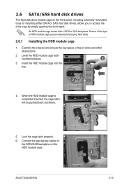
... you to the SATA/SAS backplane on the front panel, including externally removable trays for mounting either SATA or SAS hard disk drives, allows you purchase before buying hard disks. 2.6.1 Installing the HDD module cage 1. Ensure of the type of wires and other obstructions. 2. Connect the appropriate cables to access the drive trays by simply opening the front bezel. An HDD module cage comes with a SATA or SAS backplane. Examine the chassis and ensure the bay...
... you to the SATA/SAS backplane on the front panel, including externally removable trays for mounting either SATA or SAS hard disk drives, allows you purchase before buying hard disks. 2.6.1 Installing the HDD module cage 1. Ensure of the type of wires and other obstructions. 2. Connect the appropriate cables to access the drive trays by simply opening the front bezel. An HDD module cage comes with a SATA or SAS backplane. Examine the chassis and ensure the bay...
User Manual
Page 44
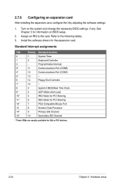
Install the software drivers for ISA or PCI devices. 2-24 Chapter 2: Hardware setup Refer to the card. Programmable Interrupt 3* 11 Communications Port (COM2) 4* 12 Communications Port (COM1) 5* 13 -- 6 14 Floppy Disk Controller 7* 15 -- 8 3 System CMOS/Real Time Clock 9* 4 ACPI Mode when used 10* 5 IRQ Holder for PCI Steering 11* 6 IRQ Holder for PCI Steering 12* 7 PS/2 Compatible Mouse Port 13 8 Numeric Data Processor 14* 9 Primary IDE Channel 15* 10 Secondary IDE...
Install the software drivers for ISA or PCI devices. 2-24 Chapter 2: Hardware setup Refer to the card. Programmable Interrupt 3* 11 Communications Port (COM2) 4* 12 Communications Port (COM1) 5* 13 -- 6 14 Floppy Disk Controller 7* 15 -- 8 3 System CMOS/Real Time Clock 9* 4 ACPI Mode when used 10* 5 IRQ Holder for PCI Steering 11* 6 IRQ Holder for PCI Steering 12* 7 PS/2 Compatible Mouse Port 13 8 Numeric Data Processor 14* 9 Primary IDE Channel 15* 10 Secondary IDE...
User Manual
Page 45
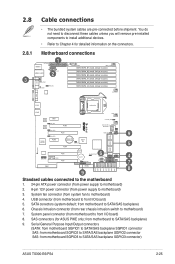
...-pin ATX power connector (from power supply to motherboard) 2. 8-pin 12V power connector (from motherboard SGPIO3 to motherboard) 3. USB connector (from system fan to front I /O board) 8. System fan connector (from motherboard to motherboard) 4. SAS connectors (for detailed information on the connectors. You do not need to disconnect these cables unless you will remove pre‑installed components to install additional devices. • Refer to motherboard) 7. Chassis Intrusion connector (from motherboard to SATA/SAS backplane) 9. from rear chassis intrusion switch to...
...-pin ATX power connector (from power supply to motherboard) 2. 8-pin 12V power connector (from motherboard SGPIO3 to motherboard) 3. USB connector (from system fan to front I /O board) 8. System fan connector (from motherboard to motherboard) 4. SAS connectors (for detailed information on the connectors. You do not need to disconnect these cables unless you will remove pre‑installed components to install additional devices. • Refer to motherboard) 7. Chassis Intrusion connector (from motherboard to SATA/SAS backplane) 9. from rear chassis intrusion switch to...
User Manual
Page 63
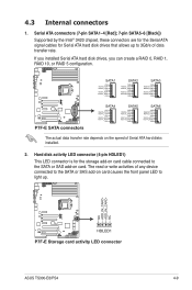
... the Intel® 3420 chipset, these connectors are for the Serial ATA signal cables for the storage add-on card cable connected to 3Gb/s of Serial ATA hard disks installed. 2. The read or write activities of any device connected to the SATA or SAS add-on card causes the front panel LED to light up to the SATA or SAS add-on the speed of data transfer rate. ASUS TS300-E6/PS4 4-9 If you installed Serial ATA hard disk drives, you can create a RAID 0, RAID 1, RAID 10, or RAID 5 configuration. 4.3 Internal connectors 1.
... the Intel® 3420 chipset, these connectors are for the Serial ATA signal cables for the storage add-on card cable connected to 3Gb/s of Serial ATA hard disks installed. 2. The read or write activities of any device connected to the SATA or SAS add-on card causes the front panel LED to light up to the SATA or SAS add-on the speed of data transfer rate. ASUS TS300-E6/PS4 4-9 If you installed Serial ATA hard disk drives, you can create a RAID 0, RAID 1, RAID 10, or RAID 5 configuration. 4.3 Internal connectors 1.
User Manual
Page 82
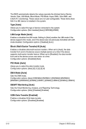
... if the device supports multi-sector transfer feature. Configuration options: [Not Installed] [Auto] [CDROM] [ARMD] LBA/Large Mode [Auto] Enables or disables the LBA mode. Setting to the system. When set to [Auto], the data transfer from and to select the data transfer mode. Configuration options: [Disabled] [Enabled] 5-10 Chapter 5: BIOS setup These values are not user-configurable. Configuration options: [Auto] [Disabled] [Enabled] 32Bit Data Transfer [Enabled] Enables or disables 32-bit data transfer. The BIOS automatically detects the values opposite...
... if the device supports multi-sector transfer feature. Configuration options: [Not Installed] [Auto] [CDROM] [ARMD] LBA/Large Mode [Auto] Enables or disables the LBA mode. Setting to the system. When set to [Auto], the data transfer from and to select the data transfer mode. Configuration options: [Disabled] [Enabled] 5-10 Chapter 5: BIOS setup These values are not user-configurable. Configuration options: [Auto] [Disabled] [Enabled] 32Bit Data Transfer [Enabled] Enables or disables 32-bit data transfer. The BIOS automatically detects the values opposite...
User Manual
Page 86
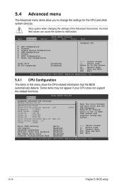
...Main Advanced Server BIOS SETUP UTILITY Power Boot Tools Exit Configure CPU. CPU Configuration Chipset Legacy Device Configuration USB Configuration PCIPnP ACPI Configuration Event Log Configuration Intel VT-d [Disabled] SR-IOV Supported [Disabled] ←→ Select Screen ↑↓ Select Item Enter Go to change the settings for the CPU and other system devices. Ratio CMOS Setting: C1E Support Hardware Prefetcher Adjacent Cache Line Prefetch Max CPUID Value Limit Intel(R) Virtualization Tech [Auto] [Enabled] [Enabled] [Enabled] [Disabled] [Enabled] F1...
...Main Advanced Server BIOS SETUP UTILITY Power Boot Tools Exit Configure CPU. CPU Configuration Chipset Legacy Device Configuration USB Configuration PCIPnP ACPI Configuration Event Log Configuration Intel VT-d [Disabled] SR-IOV Supported [Disabled] ←→ Select Screen ↑↓ Select Item Enter Go to change the settings for the CPU and other system devices. Ratio CMOS Setting: C1E Support Hardware Prefetcher Adjacent Cache Line Prefetch Max CPUID Value Limit Intel(R) Virtualization Tech [Auto] [Enabled] [Enabled] [Enabled] [Disabled] [Enabled] F1...
User Manual
Page 93
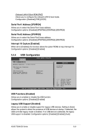
... options: [Disabled] [Enabled] 5.4.4 USB Configuration Advanced BIOS SETUP UTILITY USB Configuration Module Version - 2.24.3-13.4 USB Devices Enabled: 2 Hubs USB Functions [Enabled] Legacy USB Support [Auto] BIOS EHCI Hand-off [Enabled] Options Disabled Enabled +F1 F10 ESC Select Screen Select Item Change Option General Help Save and Exit Exit v02.61 (C)Copyright 1985-2008, American Megatrends, Inc. Configuration options: [Disabled] [Enabled] [Auto] ASUS TS300-E6 Series 5-21 Configuration options: [Disabled] [3F8/IRQ4] [3E8/IRQ4] [2E8/IRQ3] Serial Port2 Address [2F8...
... options: [Disabled] [Enabled] 5.4.4 USB Configuration Advanced BIOS SETUP UTILITY USB Configuration Module Version - 2.24.3-13.4 USB Devices Enabled: 2 Hubs USB Functions [Enabled] Legacy USB Support [Auto] BIOS EHCI Hand-off [Enabled] Options Disabled Enabled +F1 F10 ESC Select Screen Select Item Change Option General Help Save and Exit Exit v02.61 (C)Copyright 1985-2008, American Megatrends, Inc. Configuration options: [Disabled] [Enabled] [Auto] ASUS TS300-E6 Series 5-21 Configuration options: [Disabled] [3F8/IRQ4] [3E8/IRQ4] [2E8/IRQ3] Serial Port2 Address [2F8...
User Manual
Page 98
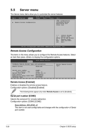
... monitoring and event log. ←→ Select Screen ↑↓ Select Item Enter Go to customize the server features. Configuration options: [COM1] [COM2] Base Address. Configuration options: [Disabled] [Enabled] The following items appear only when Remote Access is not user-configurable and changes with the configuration of Serial port number. 5-26 Chapter 5: BIOS setup Serial port number Base Address, IRQ Serial Port Mode Flow Control Redirection After BIOS POST Terminal Type [COM2] [2F8h, 3] [57600 8,n,1] [Hardware] [Disabled] [VT-UTF8] Remote Access [Enabled...
... monitoring and event log. ←→ Select Screen ↑↓ Select Item Enter Go to customize the server features. Configuration options: [COM1] [COM2] Base Address. Configuration options: [Disabled] [Enabled] The following items appear only when Remote Access is not user-configurable and changes with the configuration of Serial port number. 5-26 Chapter 5: BIOS setup Serial port number Base Address, IRQ Serial Port Mode Flow Control Redirection After BIOS POST Terminal Type [COM2] [2F8h, 3] [57600 8,n,1] [Hardware] [Disabled] [VT-UTF8] Remote Access [Enabled...
User Manual
Page 100
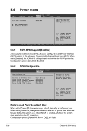
... to enable or disable the Advanced Configuration and Power Interface (ACPI) support in the RSDT pointer list. When set to [Power Off], the system goes into either off state after an AC power loss. When set to RSDT pointer list. ←→ Select Screen ↑↓ Select Item +- Configuration options: [Power Off] [Power On] [Last State] 5-28 Chapter 5: BIOS setup 5.6 Power menu Main Advanced Server BIOS SETUP UTILITY Power Boot Tools ACPI APIC support [Enabled] APM Configuration Hardware Monitor Exit...
... to enable or disable the Advanced Configuration and Power Interface (ACPI) support in the RSDT pointer list. When set to [Power Off], the system goes into either off state after an AC power loss. When set to RSDT pointer list. ←→ Select Screen ↑↓ Select Item +- Configuration options: [Power Off] [Power On] [Last State] 5-28 Chapter 5: BIOS setup 5.6 Power menu Main Advanced Server BIOS SETUP UTILITY Power Boot Tools ACPI APIC support [Enabled] APM Configuration Hardware Monitor Exit...
User Manual
Page 105
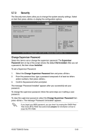
Main Advanced BIOS SETUP UTILITY Server Power Boot Tools Exit Security Settings Supervisor Password : Not Installed User Password : Not Installed to display the configuration options. The Supervisor Password item on how to disable password. To set your BIOS password, you can clear it by erasing the CMOS Real Time Clock (RTC) RAM. To clear the supervisor password, select the Change Supervisor Password then press . From the password box, type a password composed of the screen shows the default Not Installed. Confirm the password when...
Main Advanced BIOS SETUP UTILITY Server Power Boot Tools Exit Security Settings Supervisor Password : Not Installed User Password : Not Installed to display the configuration options. The Supervisor Password item on how to disable password. To set your BIOS password, you can clear it by erasing the CMOS Real Time Clock (RTC) RAM. To clear the supervisor password, select the Change Supervisor Password then press . From the password box, type a password composed of the screen shows the default Not Installed. Confirm the password when...
User Manual
Page 106
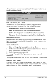
...], BIOS checks for user password when accessing the Setup utility. Configuration options: [Setup] [Always] 5-34 Chapter 5: BIOS setup On the password box that appears, type a password composed of the screen shows the default Not Installed. Change User Password Select this item shows Installed. Confirm the password when prompted. After you to [Setup], BIOS checks for user password both when accessing Setup and booting the system. To set a User Password: 1. Main Advanced BIOS SETUP UTILITY Server Power Boot Tools Supervisor Password : Installed User Password...
...], BIOS checks for user password when accessing the Setup utility. Configuration options: [Setup] [Always] 5-34 Chapter 5: BIOS setup On the password box that appears, type a password composed of the screen shows the default Not Installed. Change User Password Select this item shows Installed. Confirm the password when prompted. After you to [Setup], BIOS checks for user password both when accessing Setup and booting the system. To set a User Password: 1. Main Advanced BIOS SETUP UTILITY Server Power Boot Tools Supervisor Password : Installed User Password...

User Manual
Page 110
... SATA RAID solutions: • LSI MegaRAID software RAID Configuration Utility (default) with RAID 0, RAID 1, and RAID 10 support (for both Linux and Windows OS). • Intel Matrix Storage Manager with RAID 0, RAID 1, RAID 10, and RAID 5 support (for SATA hard disk drive installation. 6-2 Chapter 6: RAID configuration Use four new hard disk drives or use an existing drive and a new drive for this setup. 6.1 Setting up RAID The motherboard comes with the Intel® 3420 southbridge controller that of two new identical hard disk drives is required for RAID set configuration...
... SATA RAID solutions: • LSI MegaRAID software RAID Configuration Utility (default) with RAID 0, RAID 1, and RAID 10 support (for both Linux and Windows OS). • Intel Matrix Storage Manager with RAID 0, RAID 1, RAID 10, and RAID 5 support (for SATA hard disk drive installation. 6-2 Chapter 6: RAID configuration Use four new hard disk drives or use an existing drive and a new drive for this setup. 6.1 Setting up RAID The motherboard comes with the Intel® 3420 southbridge controller that of two new identical hard disk drives is required for RAID set configuration...

User Manual
Page 112
... commands. The utility main window appears. Turn on the next page. Refer to the menu level. The keys on the legend box allow you to enter the utility. LSI Software RAID Configuration Utility Ver A.62 Apr 29, 2009 BIOS Version A.09.04300936R Management Menu Configure Initialize Objects Rebuild Check Consistency Configure VD(s) Use Cursor Keys to the SATA connectors supported by the motherboard southbridge chip. 6.2 LSI Software RAID Configuration Utility The LSI MegaRAID software RAID configuration utility allows you to create RAID 0, RAID 1, or RAID...
... commands. The utility main window appears. Turn on the next page. Refer to the menu level. The keys on the legend box allow you to enter the utility. LSI Software RAID Configuration Utility Ver A.62 Apr 29, 2009 BIOS Version A.09.04300936R Management Menu Configure Initialize Objects Rebuild Check Consistency Configure VD(s) Use Cursor Keys to the SATA connectors supported by the motherboard southbridge chip. 6.2 LSI Software RAID Configuration Utility The LSI MegaRAID software RAID configuration utility allows you to create RAID 0, RAID 1, or RAID...
User Manual
Page 114
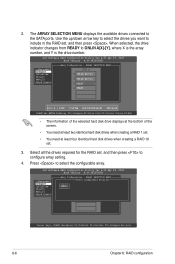
..., 2009 BIOS Version A.09.04300936R Easy Configuration - LSI Software RAID Configuration Utility Ver A.62 Apr 29, 2009 BIOS Version A.09.04300936R Management Menu Configure Initialize Objects Rebuild Check Consistency Easy Configuration - ARRAY SELECTION MENU Management Menu Configure Initialize Objects Rebuild Check Consistency PORT # 0 ONLIN A00-00 1 ONLIN A00-01 2 READY 3 READY Port # 1 DISK 77247MB HDS728080PLA380 PF20A60A SPACE-Sel,ENTER-EndArray,F10-Configure,F2-Drive Info,F3-Virtual Drives,F4-HSP • The information of the selected hard disk drive displays at...
..., 2009 BIOS Version A.09.04300936R Easy Configuration - LSI Software RAID Configuration Utility Ver A.62 Apr 29, 2009 BIOS Version A.09.04300936R Management Menu Configure Initialize Objects Rebuild Check Consistency Easy Configuration - ARRAY SELECTION MENU Management Menu Configure Initialize Objects Rebuild Check Consistency PORT # 0 ONLIN A00-00 1 ONLIN A00-01 2 READY 3 READY Port # 1 DISK 77247MB HDS728080PLA380 PF20A60A SPACE-Sel,ENTER-EndArray,F10-Configure,F2-Drive Info,F3-Virtual Drives,F4-HSP • The information of the selected hard disk drive displays at...
User Manual
Page 119
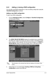
... . ASUS TS300-E6/PS4 6-11 6.2.2 Adding or viewing a RAID configuration You can add a new RAID configuration or view an existing configuration using the View/Add Configuration command. Adding a new RAID configuration To add a new RAID configuration: 1. LSI Software RAID Configuration Utility Ver A.62 Apr 29, 2009 BIOS Version A.09.04300936R Configuration Menu Easy Configuration Management MNeenwu Configuration Configure View/Add Configuration Initialize Clear Configuration Objects Select Boot Drive Rebuild Check Consistency View/Add to the SATA ports. Select the drive(s) you...
... . ASUS TS300-E6/PS4 6-11 6.2.2 Adding or viewing a RAID configuration You can add a new RAID configuration or view an existing configuration using the View/Add Configuration command. Adding a new RAID configuration To add a new RAID configuration: 1. LSI Software RAID Configuration Utility Ver A.62 Apr 29, 2009 BIOS Version A.09.04300936R Configuration Menu Easy Configuration Management MNeenwu Configuration Configure View/Add Configuration Initialize Clear Configuration Objects Select Boot Drive Rebuild Check Consistency View/Add to the SATA ports. Select the drive(s) you...
User Manual
Page 122
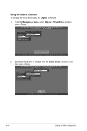
... Vitual Drive(1) Virtual Drive 0 Objects Management MAednaupter Configure Virtual Drive Initialize Physical Drive Objects Rebuild Check Consistency Select VD Press ENTER To Select A VD, To Delete A VD 6-14 Chapter 6: RAID configuration Using the Objects command To initialize the virtual drives using the Objects command 1. LSI Software RAID Configuration Utility Ver A.62 Apr 29, 2009 BIOS Version A.09.04300936R Objects Management MAednaupter Configure Virtual Drive Initialize Physical Drive Objects Rebuild Check Consistency Change VD Parameters Use Cursor Keys To...
... Vitual Drive(1) Virtual Drive 0 Objects Management MAednaupter Configure Virtual Drive Initialize Physical Drive Objects Rebuild Check Consistency Select VD Press ENTER To Select A VD, To Delete A VD 6-14 Chapter 6: RAID configuration Using the Objects command To initialize the virtual drives using the Objects command 1. LSI Software RAID Configuration Utility Ver A.62 Apr 29, 2009 BIOS Version A.09.04300936R Objects Management MAednaupter Configure Virtual Drive Initialize Physical Drive Objects Rebuild Check Consistency Change VD Parameters Use Cursor Keys To...
User Manual
Page 144
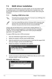
... command prompt 5. 7.1 RAID driver installation After creating the RAID sets for your changes, and then exit the BIOS Setup. 4. A floppy disk with the LSI Software RAID configuration utility, the boot priority of RAID driver disk you want to create and press to boot from the connected SATA ODD. Place the motherboard support DVD in a RAID set. Select the optical drive as the first boot priority to enter the sub-menu. The Makedisk menu appears. This part provides instructions on a hard disk drive that is required when installing Windows...
... command prompt 5. 7.1 RAID driver installation After creating the RAID sets for your changes, and then exit the BIOS Setup. 4. A floppy disk with the LSI Software RAID configuration utility, the boot priority of RAID driver disk you want to create and press to boot from the connected SATA ODD. Place the motherboard support DVD in a RAID set. Select the optical drive as the first boot priority to enter the sub-menu. The Makedisk menu appears. This part provides instructions on a hard disk drive that is required when installing Windows...


