User Guide
Page 4
... FM radio station 3-11 3.5.3 Presetting a station 3-12 3.5.4 Adjusting the volume 3-12 Chapter 4: Motherboard Info 4.1 Introduction 4-2 4.2 Motherboard layout 4-2 4.3 Jumpers 4-3 4.4 Connectors 4-5 Chapter 5: BIOS Information 5.1 Managing and updating your BIOS 5-2 5.1.1 Creating a bootable floppy disk 5-2 5.1.2 ASUS EZ Flash utility 5-3 5.1.3 AFUDOS utility 5-4 5.1.4 ASUS CrashFree BIOS 2 utility 5-6 5.1.5 ASUS Update utility 5-8 5.2 BIOS setup program 5-11 5.2.1 BIOS menu screen 5-12 5.2.2 Menu bar 5-12...
... FM radio station 3-11 3.5.3 Presetting a station 3-12 3.5.4 Adjusting the volume 3-12 Chapter 4: Motherboard Info 4.1 Introduction 4-2 4.2 Motherboard layout 4-2 4.3 Jumpers 4-3 4.4 Connectors 4-5 Chapter 5: BIOS Information 5.1 Managing and updating your BIOS 5-2 5.1.1 Creating a bootable floppy disk 5-2 5.1.2 ASUS EZ Flash utility 5-3 5.1.3 AFUDOS utility 5-4 5.1.4 ASUS CrashFree BIOS 2 utility 5-6 5.1.5 ASUS Update utility 5-8 5.2 BIOS setup program 5-11 5.2.1 BIOS menu screen 5-12 5.2.2 Menu bar 5-12...
User Guide
Page 8
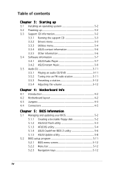
... connector locations. 5. How this guide is intended for this guide Audience This guide provides general information and installation instructions about the motherboard that comes with hardware knowledge of the ASUS T2-PH1. Appendix The Appendix includes the power supply unit specification for experienced users and integrators with the system. The chapter lists the system...
... connector locations. 5. How this guide is intended for this guide Audience This guide provides general information and installation instructions about the motherboard that comes with hardware knowledge of the ASUS T2-PH1. Appendix The Appendix includes the power supply unit specification for experienced users and integrators with the system. The chapter lists the system...
User Guide
Page 10
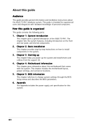
... • Optical drive (CD-ROM/CD-RW/DVD-ROM/DVD-RW) • Floppy disk drive x P H 1 b a r e b o n e s y s t e m with • ASUS motherboard • 250 W PFC/non-PFC power supply unit • Gigabit LAN port • CPU fan and heatsink assembly • 2 x 5.25" drive bays • 1 x 3.5" floppy disk ... • AC power cable • Serial ATA cable • Serial ATA power cable 3 . User guide 5 . System package contents Check your T2-PH1 system package for the following items. If any of the items is damaged or missing, contact your retailer immediately. Item description 1 .
... • Optical drive (CD-ROM/CD-RW/DVD-ROM/DVD-RW) • Floppy disk drive x P H 1 b a r e b o n e s y s t e m with • ASUS motherboard • 250 W PFC/non-PFC power supply unit • Gigabit LAN port • CPU fan and heatsink assembly • 2 x 5.25" drive bays • 1 x 3.5" floppy disk ... • AC power cable • Serial ATA cable • Serial ATA power cable 3 . User guide 5 . System package contents Check your T2-PH1 system package for the following items. If any of the items is damaged or missing, contact your retailer immediately. Item description 1 .
User Guide
Page 12
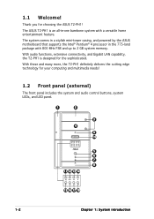
...-tower casing, and powered by the ASUS motherboard that supports the Intel® Pentium® 4 processor in -one barebone system with 800 MHz FSB and up to 2 GB system memory. With these and many more, the T2-PH1 definitely delivers the cutting edge technology for the sophisticated. The ASUS T2-PH1 is designed for your computing and...
...-tower casing, and powered by the ASUS motherboard that supports the Intel® Pentium® 4 processor in -one barebone system with 800 MHz FSB and up to 2 GB system memory. With these and many more, the T2-PH1 definitely delivers the cutting edge technology for the sophisticated. The ASUS T2-PH1 is designed for your computing and...
User Guide
Page 19
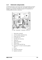
... 3. Chassis fan 7. Serial ATA connectors 13. PCI Express™ x16 slot for your reference. Hard disk drive metal tray 6. DIMM sockets 9. Expansion card slots ASUS T2-PH1 1-9 Front panel cover 5. ASUS motherboard 8. Proceed to Chapter 2 for instructions on installing additional system components. 1 6 3 2 9 8 7 4 5 10 13 11 12 1. LGA775 socket with PnP cap 10. PCI slot 12...
... 3. Chassis fan 7. Serial ATA connectors 13. PCI Express™ x16 slot for your reference. Hard disk drive metal tray 6. DIMM sockets 9. Expansion card slots ASUS T2-PH1 1-9 Front panel cover 5. ASUS motherboard 8. Proceed to Chapter 2 for instructions on installing additional system components. 1 6 3 2 9 8 7 4 5 10 13 11 12 1. LGA775 socket with PnP cap 10. PCI slot 12...
User Guide
Page 22
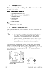
... sure that the standby power LED is ON, in sleep mode or in the system. DDR Dual Inline Memory Module (DIMM) 3. Hard disk drive 5. The motherboard comes with the component. Unplug the power cable from the power outlet and make sure that you have all the components you uninstall any system...
... sure that the standby power LED is ON, in sleep mode or in the system. DDR Dual Inline Memory Module (DIMM) 3. Hard disk drive 5. The motherboard comes with the component. Unplug the power cable from the power outlet and make sure that you have all the components you uninstall any system...
User Guide
Page 24
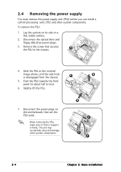
... a flat, stable surface. 2. Disconnect the optical drive and floppy disk drive power plugs. 3. Slightly lift the PSU. 7. Lay the system on its side on the motherboard, then set the PSU aside. The unit may accidentally drop and damage other system components. Remove the screw that secures 3 the PSU to hold or...
... a flat, stable surface. 2. Disconnect the optical drive and floppy disk drive power plugs. 3. Slightly lift the PSU. 7. Lay the system on its side on the motherboard, then set the PSU aside. The unit may accidentally drop and damage other system components. Remove the screw that secures 3 the PSU to hold or...
User Guide
Page 25
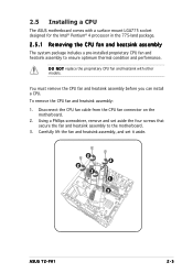
Using a Phillips screwdriver, remove and set it aside. 2 2 2 2 1 3 ASUS T2-PH1 2-5 Disconnect the CPU fan cable from the CPU fan connector on the motherboard. 2. Carefully lift the fan and heatsink assembly, and set aside the four screws that secure the fan and heatsink ...assembly to ensure optimum thermal condition and performance. To remove the CPU fan and heatsink assembly: 1. 2.5 Installing a CPU The ASUS motherboard comes with other models. You must remove the CPU fan and heatsink assembly before you can install a CPU. D O N O T replace the ...
Using a Phillips screwdriver, remove and set it aside. 2 2 2 2 1 3 ASUS T2-PH1 2-5 Disconnect the CPU fan cable from the CPU fan connector on the motherboard. 2. Carefully lift the fan and heatsink assembly, and set aside the four screws that secure the fan and heatsink ...assembly to ensure optimum thermal condition and performance. To remove the CPU fan and heatsink assembly: 1. 2.5 Installing a CPU The ASUS motherboard comes with other models. You must remove the CPU fan and heatsink assembly before you can install a CPU. D O N O T replace the ...
User Guide
Page 26
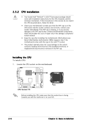
ASUS will process Return Merchandise Authorization (RMA) requests only if the motherboard comes with installation instructions for the CPU, heatsink, and the retention mechanism. Installing the CPU To install a CPU: 1. 2.5.2 CPU installation • Your boxed Intel®... is facing towards you see any damage to make sure that the PnP cap is shipment/ transit-related. • Keep the cap after installing the motherboard. ASUS will shoulder the cost of the PnP cap. Contact your left. 2-6 Chapter 2: Basic installation If the instructions in this section do not match the ...
ASUS will process Return Merchandise Authorization (RMA) requests only if the motherboard comes with installation instructions for the CPU, heatsink, and the retention mechanism. Installing the CPU To install a CPU: 1. 2.5.2 CPU installation • Your boxed Intel®... is facing towards you see any damage to make sure that the PnP cap is shipment/ transit-related. • Keep the cap after installing the motherboard. ASUS will shoulder the cost of the PnP cap. Contact your left. 2-6 Chapter 2: Basic installation If the instructions in this section do not match the ...
User Guide
Page 29
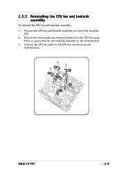
Position the CPU fan and heatsink assembly on the motherboard. 2 2 2 2 3 1 ASUS T2-PH1 2-9 Drive in the four screws you removed earlier into the CPU fan screw holes to secure the fan and heatsink assembly to the CPU fan connector on top of the installed CPU. 2. Connect the CPU fan cable to the motherboard. 3. 2.5.3 Reinstalling the CPU fan and heatsink assembly To reinstall the CPU fan and heatsink assembly: 1.
Position the CPU fan and heatsink assembly on the motherboard. 2 2 2 2 3 1 ASUS T2-PH1 2-9 Drive in the four screws you removed earlier into the CPU fan screw holes to secure the fan and heatsink assembly to the CPU fan connector on top of the installed CPU. 2. Connect the CPU fan cable to the motherboard. 3. 2.5.3 Reinstalling the CPU fan and heatsink assembly To reinstall the CPU fan and heatsink assembly: 1.
User Guide
Page 30
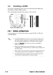
...installation For optimum compatibility, we recommend that you obtain memory modules from the same vendor. • Due to 2 GB system memory using 256 MB, 512 MB, and 1 GB DDR DIMMs. • Installing DDR DIMMS other than the recommended configurations may detect less than 2 GB system memory when ...you installed two 1 GB DDR memory. • This motherboard does not support memory modules made up of the recommended configurations in the table on the ...
...installation For optimum compatibility, we recommend that you obtain memory modules from the same vendor. • Due to 2 GB system memory using 256 MB, 512 MB, and 1 GB DDR DIMMs. • Installing DDR DIMMS other than the recommended configurations may detect less than 2 GB system memory when ...you installed two 1 GB DDR memory. • This motherboard does not support memory modules made up of the recommended configurations in the table on the ...
User Guide
Page 32
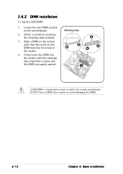
2.6.2 DIMM installation To install a DDR DIMM: 1. Retaining clips 2 2 3 4 4 1 A DDR DIMM is properly seated. Align a DIMM on the socket such that it fits in only one direction. DO NOT force a DIMM into the socket until the retaining clips snap back in place and the DIMM is keyed with a notch so that the notch on the DIMM matches the break on the motherboard. 2. Firmly insert the DIMM into a socket to avoid damaging the DIMM! 2-12 Chapter 2: Basic installation Locate the two DIMM sockets on the socket. 4. Unlock a socket by pressing the retaining clips outward. 3.
2.6.2 DIMM installation To install a DDR DIMM: 1. Retaining clips 2 2 3 4 4 1 A DDR DIMM is properly seated. Align a DIMM on the socket such that it fits in only one direction. DO NOT force a DIMM into the socket until the retaining clips snap back in place and the DIMM is keyed with a notch so that the notch on the DIMM matches the break on the motherboard. 2. Firmly insert the DIMM into a socket to avoid damaging the DIMM! 2-12 Chapter 2: Basic installation Locate the two DIMM sockets on the socket. 4. Unlock a socket by pressing the retaining clips outward. 3.
User Guide
Page 33
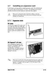
... cord before installing a PCI Express™ x16 graphic card. The figure shows a graphics card installed on the motherboard before adding or removing expansion cards. The following figure shows a LAN card installed on a PCI slot. ASUS T2-PH1 2-13 Failure to do so may need to the ATX12V2 connector on the PCI Express™ x16...
... cord before installing a PCI Express™ x16 graphic card. The figure shows a graphics card installed on the motherboard before adding or removing expansion cards. The following figure shows a LAN card installed on a PCI slot. ASUS T2-PH1 2-13 Failure to do so may need to the ATX12V2 connector on the PCI Express™ x16...
User Guide
Page 35
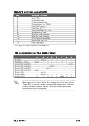
... Processor 14* Primary IDE Channel * These IRQs are usually available for this motherboard PCI slot 1 PCI Express x16 slot Onboard USB controller 1 Onboard USB controller 2 Onboard USB controller 3 Onboard USB controller 4 Onboard LAN Onboard Audio Onboard 1394 A B CD E -- shared -- -- ASUS T2-PH1 2-15 shared -- -- -- shared -- -- -- -- -- -- -- -- shared -- -- -- -- -- -- -- -- -- -- -- -- shared -- -- -- -- otherwise, conflicts will arise between the two...
... Processor 14* Primary IDE Channel * These IRQs are usually available for this motherboard PCI slot 1 PCI Express x16 slot Onboard USB controller 1 Onboard USB controller 2 Onboard USB controller 3 Onboard USB controller 4 Onboard LAN Onboard Audio Onboard 1394 A B CD E -- shared -- -- ASUS T2-PH1 2-15 shared -- -- -- shared -- -- -- -- -- -- -- -- shared -- -- -- -- -- -- -- -- -- -- -- -- shared -- -- -- -- otherwise, conflicts will arise between the two...
User Guide
Page 37
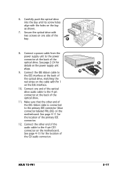
.... 7 8 9 ASUS T2-PH1 2-17 Secure the optical drive with two screws on the power supply unit plugs. 10 9. See page 4-13 for the location of the optical drive. 11. See page 4-11 for the location of the bay. 6 8. Connect a power cable from the power supply unit to the 4-pin CD1 connector on the motherboard.
.... 7 8 9 ASUS T2-PH1 2-17 Secure the optical drive with two screws on the power supply unit plugs. 10 9. See page 4-13 for the location of the optical drive. 11. See page 4-11 for the location of the bay. 6 8. Connect a power cable from the power supply unit to the 4-pin CD1 connector on the motherboard.
User Guide
Page 39
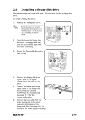
.... ASUS T2-PH1 6 4 2-19 Secure the floppy disk drive with one 3.25-inch drive bay for a floppy disk drive. 2.9 Installing a floppy disk drive The barebone system comes with two screws. 33 4. For instructions on how to remove the front panel cover, refer to the floppy disk drive connector (labeled FLOPPY) on the motherboard. Connect...
.... ASUS T2-PH1 6 4 2-19 Secure the floppy disk drive with one 3.25-inch drive bay for a floppy disk drive. 2.9 Installing a floppy disk drive The barebone system comes with two screws. 33 4. For instructions on how to remove the front panel cover, refer to the floppy disk drive connector (labeled FLOPPY) on the motherboard. Connect...
User Guide
Page 41
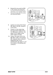
... 40-pin IDE cable to the HDD power connector. Connect a 4-pin power plug from the power supply unit to the IDE connector on the drive. 9. ASUS T2-PH1 2-21 See 8 page 2-24 for the location of the IDE ribbon cable to the chassis hooks. 7. Connect the other end of the primary IDE connector... labeled PRI_IDE) on the power supply unit plugs. 9 10. Secure the tray with the screw you removed earlier. 6 7 8. See page 4-11 for details on the motherboard. 6.
... 40-pin IDE cable to the HDD power connector. Connect a 4-pin power plug from the power supply unit to the IDE connector on the drive. 9. ASUS T2-PH1 2-21 See 8 page 2-24 for the location of the IDE ribbon cable to the chassis hooks. 7. Connect the other end of the primary IDE connector... labeled PRI_IDE) on the power supply unit plugs. 9 10. Secure the tray with the screw you removed earlier. 6 7 8. See page 4-11 for details on the motherboard. 6.
User Guide
Page 42
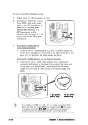
... from becoming unstable. To install a Serial ATA hard disk drive: 1. Follow steps 1-7 of the Serial ATA connectors. 3a 3. See page 4-12 for details on the motherboard.
... from becoming unstable. To install a Serial ATA hard disk drive: 1. Follow steps 1-7 of the Serial ATA connectors. 3a 3. See page 4-12 for details on the motherboard.
User Guide
Page 43
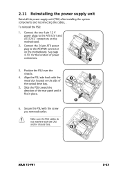
Connect the two 4-pin 12 V power plugs to the ATXPWR connector on the motherboard. Align the PSU side hook with the 4 3 metal slot located on the motherboard. 2. Make sure the PSU cables do not interfere with the screw you removed earlier. See page 4-10 for the location of the rear panel until ... system components and reconnecting the cables, . Slide the PSU toward the direction of power connectors. 2 1 1 3. Secure the PSU with the CPU and/or chassis fans. 6 ASUS T2-PH1 2-23
Connect the two 4-pin 12 V power plugs to the ATXPWR connector on the motherboard. Align the PSU side hook with the 4 3 metal slot located on the motherboard. 2. Make sure the PSU cables do not interfere with the screw you removed earlier. See page 4-10 for the location of the rear panel until ... system components and reconnecting the cables, . Slide the PSU toward the direction of power connectors. 2 1 1 3. Secure the PSU with the CPU and/or chassis fans. 6 ASUS T2-PH1 2-23
User Guide
Page 48
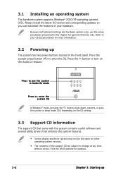
...restarts, or puts the system in the front panel. Press the system power button ( ) to change at any time without notice. Because motherboard settings and hardware options vary, use the setup procedures presented in this chapter for updates. 3-2 Chapter 3: Starting up The system has two ... contents of your hardware. 3.1 Installing an operating system The barebone system supports Windows® 2000/XP operating systems (OS). Visit the ASUS website for general reference only. Always install the latest OS version and corresponding updates so you can maximize the features of the support CD...
...restarts, or puts the system in the front panel. Press the system power button ( ) to change at any time without notice. Because motherboard settings and hardware options vary, use the setup procedures presented in this chapter for updates. 3-2 Chapter 3: Starting up The system has two ... contents of your hardware. 3.1 Installing an operating system The barebone system supports Windows® 2000/XP operating systems (OS). Visit the ASUS website for general reference only. Always install the latest OS version and corresponding updates so you can maximize the features of the support CD...


