T2-PE1 English User Manual E2151
Page 4
... 3: Starting up 3.1 Installing an operating system 3-2 3.2 Powering up 3-2 3.3 Support CD information 3-2 3.3.1 Running the support CD 3-3 3.3.2 Drivers menu 3-3 3.3.3 Utilities menu 3-4 3.3.4 ASUS contact information 3-5 3.3.5 Other information 3-6 3.4 Software information 3-7 3.4.1 ASUS Instant Music 3-7 3.4.2 ASUS Update 3-9 3.4.3 ASUS PC Probe II 3-11 Chapter 4: Motherboard Info 4.1 Introduction 4-2 4.2 Motherboard layout 4-2 4.3 Jumper 4-3 4.4 Connectors 4-4 Chapter 5: BIOS Information 5.1 Managing and updating your BIOS 5-2 5.1.1 Creating a bootable floppy disk...
... 3: Starting up 3.1 Installing an operating system 3-2 3.2 Powering up 3-2 3.3 Support CD information 3-2 3.3.1 Running the support CD 3-3 3.3.2 Drivers menu 3-3 3.3.3 Utilities menu 3-4 3.3.4 ASUS contact information 3-5 3.3.5 Other information 3-6 3.4 Software information 3-7 3.4.1 ASUS Instant Music 3-7 3.4.2 ASUS Update 3-9 3.4.3 ASUS PC Probe II 3-11 Chapter 4: Motherboard Info 4.1 Introduction 4-2 4.2 Motherboard layout 4-2 4.3 Jumper 4-3 4.4 Connectors 4-4 Chapter 5: BIOS Information 5.1 Managing and updating your BIOS 5-2 5.1.1 Creating a bootable floppy disk...
T2-PE1 English User Manual E2151
Page 8
...viii This guide is intended for this guide is organized This guide contains the following parts: 1. Chapter 4: Motherboard information This chapter gives information about the ASUS Terminator 2 barebone system. Chapter 5: BIOS information This chapter tells how to install components in the system. ...BIOS parameters. 6. About this guide Audience This guide provides general information and installation instructions about the motherboard that comes with hardware knowledge of the ASUS Terminator 2. Chapter 3: Starting up This chapter helps you power up the system and install drivers and...
...viii This guide is intended for this guide is organized This guide contains the following parts: 1. Chapter 4: Motherboard information This chapter gives information about the ASUS Terminator 2 barebone system. Chapter 5: BIOS information This chapter tells how to install components in the system. ...BIOS parameters. 6. About this guide Audience This guide provides general information and installation instructions about the motherboard that comes with hardware knowledge of the ASUS Terminator 2. Chapter 3: Starting up This chapter helps you power up the system and install drivers and...
T2-PE1 English User Manual E2151
Page 10
P E 1 b a r e b o n e s y s t e m with • ASUS motherboard • 250 W Passive PFC power supply unit • PCI Express™ Gigabit LAN port • CPU fan and heatsink assembly • 2 x 5.25" drive bays • 1 x 3.5" ... • Optical drive (CD-ROM/CD-RW/DVD-ROM/DVD-RW) • Floppy disk drive • Floppy disk drive cable x System package contents Check your T2-PE1 system package for the following items. If any of the items is damaged or missing, contact your retailer immediately. Cables • AC power cable •...
P E 1 b a r e b o n e s y s t e m with • ASUS motherboard • 250 W Passive PFC power supply unit • PCI Express™ Gigabit LAN port • CPU fan and heatsink assembly • 2 x 5.25" drive bays • 1 x 3.5" ... • Optical drive (CD-ROM/CD-RW/DVD-ROM/DVD-RW) • Floppy disk drive • Floppy disk drive cable x System package contents Check your T2-PE1 system package for the following items. If any of the items is damaged or missing, contact your retailer immediately. Cables • AC power cable •...
T2-PE1 English User Manual E2151
Page 12
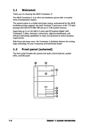
The ASUS Terminator 2 is an all-in the 775-land package with a versatile home entertainment feature. Thank you for your personal as well as business requirements. Supporting ... 1: System introduction With these and many more, the Terminator 2 definitely delivers the cutting edge technology for choosing the ASUS Terminator 2! 1.1 Welcome! The system comes in a stylish mini-tower casing, and powered by the ASUS motherboard that supports the Intel® Pentium® 4 processor in -one barebone system with 800/533 MHz FSB and...
The ASUS Terminator 2 is an all-in the 775-land package with a versatile home entertainment feature. Thank you for your personal as well as business requirements. Supporting ... 1: System introduction With these and many more, the Terminator 2 definitely delivers the cutting edge technology for choosing the ASUS Terminator 2! 1.1 Welcome! The system comes in a stylish mini-tower casing, and powered by the ASUS motherboard that supports the Intel® Pentium® 4 processor in -one barebone system with 800/533 MHz FSB and...
T2-PE1 English User Manual E2151
Page 17
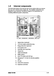
... discrete graphics card 11. Floppy disk drive (optional) 4. Chassis fan 7. ASUS motherboard 8. PCI Express™ x16 slot for instructions on installing additional system components. 1 6 3 2 9 7 10 11 13 4 8 5 12 1. The installed components are labeled for your reference. DIMM sockets 9. Expansion card slots ASUS T2-PE1 1-7 LGA 775 socket with PnP cap 10. Serial ATA connectors 13...
... discrete graphics card 11. Floppy disk drive (optional) 4. Chassis fan 7. ASUS motherboard 8. PCI Express™ x16 slot for instructions on installing additional system components. 1 6 3 2 9 7 10 11 13 4 8 5 12 1. The installed components are labeled for your reference. DIMM sockets 9. Expansion card slots ASUS T2-PE1 1-7 LGA 775 socket with PnP cap 10. Serial ATA connectors 13...
T2-PE1 English User Manual E2151
Page 20
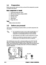
DDR Dual Inline Memory Module (DIMM) 3. The motherboard comes with the component. Expansion card(s) 4. Hard disk drive 5. This LED lights up to avoid touching the ICs on a grounded antistatic pad or in the ...
DDR Dual Inline Memory Module (DIMM) 3. The motherboard comes with the component. Expansion card(s) 4. Hard disk drive 5. This LED lights up to avoid touching the ICs on a grounded antistatic pad or in the ...
T2-PE1 English User Manual E2151
Page 22
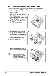
... the PSU, make sure to the chassis. 4. The unit may accidentally drop and damage other system components. Lay the system on its side on the motherboard, then set the PSU aside. To remove the PSU: 1. Disconnect the optical drive and floppy disk drive power plugs. 3. 2.4 Removing the power supply unit You...
... the PSU, make sure to the chassis. 4. The unit may accidentally drop and damage other system components. Lay the system on its side on the motherboard, then set the PSU aside. To remove the PSU: 1. Disconnect the optical drive and floppy disk drive power plugs. 3. 2.4 Removing the power supply unit You...
T2-PE1 English User Manual E2151
Page 23
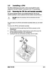
...you can install a CPU. Carefully lift the fan and heatsink assembly, and set it aside. 2 2 2 2 1 ASUS T2-PE1 2-5 To remove the CPU fan and heatsink assembly: 1. Disconnect the CPU fan cable from the CPU fan connector on the motherboard. 2. Using a Phillips screwdriver, release the four screws that secure the fan and heatsink assembly to... 775-land package. 2.5.1 Removing the CPU fan and heatsink assembly The system package includes a pre-installed proprietary CPU fan and heatsink assembly to the motherboard. 3. 2.5 Installing a CPU The ASUS motherboard comes with other models.
...you can install a CPU. Carefully lift the fan and heatsink assembly, and set it aside. 2 2 2 2 1 ASUS T2-PE1 2-5 To remove the CPU fan and heatsink assembly: 1. Disconnect the CPU fan cable from the CPU fan connector on the motherboard. 2. Using a Phillips screwdriver, release the four screws that secure the fan and heatsink assembly to... 775-land package. 2.5.1 Removing the CPU fan and heatsink assembly The system package includes a pre-installed proprietary CPU fan and heatsink assembly to the motherboard. 3. 2.5 Installing a CPU The ASUS motherboard comes with other models.
T2-PE1 English User Manual E2151
Page 24
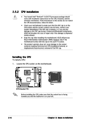
ASUS will shoulder the cost of the PnP cap. Locate the CPU socket on the motherboard. ¤ CPU Socket 775 Before installing the CPU, make sure that the socket box is facing towards you see any damage to the socket ... make sure that the PnP cap is shipment/ transit-related. • Keep the cap after installing the motherboard. ASUS will process Return Merchandise Authorization (RMA) requests only if the motherboard comes with installation instructions for the CPU, heatsink, and the retention mechanism. 2.5.2 CPU installation • Your boxed Intel® Pentium® 4 LGA775 ...
ASUS will shoulder the cost of the PnP cap. Locate the CPU socket on the motherboard. ¤ CPU Socket 775 Before installing the CPU, make sure that the socket box is facing towards you see any damage to the socket ... make sure that the PnP cap is shipment/ transit-related. • Keep the cap after installing the motherboard. ASUS will process Return Merchandise Authorization (RMA) requests only if the motherboard comes with installation instructions for the CPU, heatsink, and the retention mechanism. 2.5.2 CPU installation • Your boxed Intel® Pentium® 4 LGA775 ...
T2-PE1 English User Manual E2151
Page 27
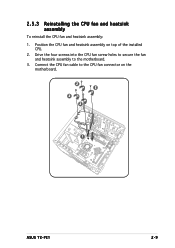
Position the CPU fan and heatsink assembly on the motherboard. 2 2 2 2 1 ASUS T2-PE1 2-9 Connect the CPU fan cable to the motherboard. 3. 2.5.3 Reinstalling the CPU fan and heatsink assembly To reinstall the CPU fan and heatsink assembly: 1. Drive the four screws into the CPU fan screw holes to secure the fan and heatsink assembly to the CPU fan connector on top of the installed CPU. 2.
Position the CPU fan and heatsink assembly on the motherboard. 2 2 2 2 1 ASUS T2-PE1 2-9 Connect the CPU fan cable to the motherboard. 3. 2.5.3 Reinstalling the CPU fan and heatsink assembly To reinstall the CPU fan and heatsink assembly: 1. Drive the four screws into the CPU fan screw holes to secure the fan and heatsink assembly to the CPU fan connector on top of the installed CPU. 2.

T2-PE1 English User Manual E2151
Page 28
104 Pins 80 Pins DIMM1 DIMM2 2.6 Installing a DIMM The system motherboard comes with the same CAS latency. The following figure illustrates the location of the recommended configurations in DIMM1 and DIMM2. • Always install DIMMs with ...
104 Pins 80 Pins DIMM1 DIMM2 2.6 Installing a DIMM The system motherboard comes with the same CAS latency. The following figure illustrates the location of the recommended configurations in DIMM1 and DIMM2. • Always install DIMMs with ...

T2-PE1 English User Manual E2151
Page 30
... such that it fits in place and 1 the DIMM is keyed with a notch so that the notch on the 2 4 DIMM matches the break on the motherboard. Locate the two DIMM sockets on 2 4 the socket. 4. Retaining clips 2. A DDR DIMM is properly seated. 2.6.2 DIMM installation To install a DDR DIMM...
... such that it fits in place and 1 the DIMM is keyed with a notch so that the notch on the 2 4 DIMM matches the break on the motherboard. Locate the two DIMM sockets on 2 4 the socket. 4. Retaining clips 2. A DDR DIMM is properly seated. 2.6.2 DIMM installation To install a DDR DIMM...
T2-PE1 English User Manual E2151
Page 31
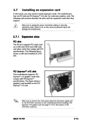
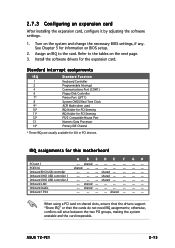
...; x16 slot for the location of the ATX12V2 connector. 2.7 Installing an expansion card In the future, you physical injury and damage the motherboard. 2.7.1 Expansion slots PCI slot The PCI slot supports PCI cards such as a LAN card, SCSI card, USB card, and other cards... that they support. PCI Express™ x16 slot This motherboard supports PCI Express™ x16 graphic cards that comply with PCI specifications. The following sub-sections describe the slots and the expansion cards that comply with PCI Express™ specifications. ASUS T2-PE1 2-13
...; x16 slot for the location of the ATX12V2 connector. 2.7 Installing an expansion card In the future, you physical injury and damage the motherboard. 2.7.1 Expansion slots PCI slot The PCI slot supports PCI cards such as a LAN card, SCSI card, USB card, and other cards... that they support. PCI Express™ x16 slot This motherboard supports PCI Express™ x16 graphic cards that comply with PCI specifications. The following sub-sections describe the slots and the expansion cards that comply with PCI Express™ specifications. ASUS T2-PE1 2-13
T2-PE1 English User Manual E2151
Page 33
... IRQ" or that the cards do not need IRQ assignments; Onboard LAN -- Refer to the card. Install the software drivers for this motherboard A BCDE F GH PCI slot 1 -- shared -- -- -- -- shared -- -- -- -- ASUS T2-PE1 2-15 When using a PCI card on the system and change the necessary BIOS settings, if any. Assign an IRQ to the tables...
... IRQ" or that the cards do not need IRQ assignments; Onboard LAN -- Refer to the card. Install the software drivers for this motherboard A BCDE F GH PCI slot 1 -- shared -- -- -- -- shared -- -- -- -- ASUS T2-PE1 2-15 When using a PCI card on the system and change the necessary BIOS settings, if any. Assign an IRQ to the tables...
T2-PE1 English User Manual E2151
Page 35
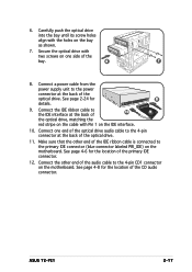
... the IDE ribbon cable is connected to the primary IDE connector (blue connector labeled PRI_IDE) on the motherboard. Carefully push the optical drive into the bay until its screw holes align with Pin 1 on the motherboard. Connect the other end of the CD audio connector. See page 2-24 for the location of... connector at the back of the audio cable to the 4-pin connector at the back of the primary IDE connector. 12. 6. See page 4-6 for 8 details. 9. ASUS T2-PE1 2-17
... the IDE ribbon cable is connected to the primary IDE connector (blue connector labeled PRI_IDE) on the motherboard. Carefully push the optical drive into the bay until its screw holes align with Pin 1 on the motherboard. Connect the other end of the CD audio connector. See page 2-24 for the location of... connector at the back of the audio cable to the 4-pin connector at the back of the primary IDE connector. 12. 6. See page 4-6 for 8 details. 9. ASUS T2-PE1 2-17

T2-PE1 English User Manual E2151
Page 36
See page 4-7 for details on the motherboard. Lock the front panel cover hooks to the Serial ATA interface at the back of Serial ATA connectors. 3. Connect a Serial ATA power cable from the ...
See page 4-7 for details on the motherboard. Lock the front panel cover hooks to the Serial ATA interface at the back of Serial ATA connectors. 3. Connect a Serial ATA power cable from the ...
T2-PE1 English User Manual E2151
Page 37
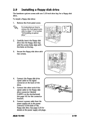
... the floppy disk drive with one 3.25-inch drive bay for a floppy disk drive. ASUS T2-PE1 6 4 2-19 For instructions on how to remove the front panel cover, refer to the floppy disk drive connector (labeled FLOPPY) on the motherboard. Connect a power cable from the power supply unit to the signal connector at the...
... the floppy disk drive with one 3.25-inch drive bay for a floppy disk drive. ASUS T2-PE1 6 4 2-19 For instructions on how to remove the front panel cover, refer to the floppy disk drive connector (labeled FLOPPY) on the motherboard. Connect a power cable from the power supply unit to the signal connector at the...
T2-PE1 English User Manual E2151
Page 39
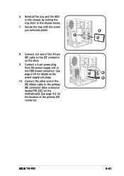
Reinstall the tray and the HDD to the chassis by locking the tray slots to the IDE connector on the drive. 9. ASUS T2-PE1 2-21 6. Connect one end of the 40-pin IDE cable to the chassis hooks. 7. Connect a 4-pin power plug from the power supply unit to the ... connector. Connect the other end of the primary IDE connector. Secure the tray with the screw you removed earlier. 6 7 8. See page 4-6 for details on the motherboard.
Reinstall the tray and the HDD to the chassis by locking the tray slots to the IDE connector on the drive. 9. ASUS T2-PE1 2-21 6. Connect one end of the 40-pin IDE cable to the chassis hooks. 7. Connect a 4-pin power plug from the power supply unit to the ... connector. Connect the other end of the primary IDE connector. Secure the tray with the screw you removed earlier. 6 7 8. See page 4-6 for details on the motherboard.
T2-PE1 English User Manual E2151
Page 40
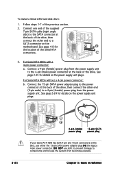
... the Serial ATA connectors. 3a 3. See page 4-8 for 2 the location of the drive, then connect the other end (4-pin male) to a SATA connector on the motherboard. Chapter 2: Basic installation D O N O T use either the 15-pin SATA power adapter plug O R the legacy 4-pin power connector. See page 2-25 for details on the power...
... the Serial ATA connectors. 3a 3. See page 4-8 for 2 the location of the drive, then connect the other end (4-pin male) to a SATA connector on the motherboard. Chapter 2: Basic installation D O N O T use either the 15-pin SATA power adapter plug O R the legacy 4-pin power connector. See page 2-25 for details on the power...
T2-PE1 English User Manual E2151
Page 41
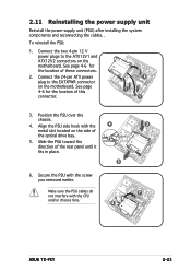
... motherboard. See page 4-6 for the location of this connector. 2 1 1 3. Slide the PSU toward the direction of the optical drive bay. 5. 2.11 Reinstalling the power supply unit Reinstall the power supply unit (PSU) after installing the system components and reconnecting the cables, . Secure the PSU with the CPU and/or chassis fans. 4 5 6 3 7 ASUS T2-PE1...
... motherboard. See page 4-6 for the location of this connector. 2 1 1 3. Slide the PSU toward the direction of the optical drive bay. 5. 2.11 Reinstalling the power supply unit Reinstall the power supply unit (PSU) after installing the system components and reconnecting the cables, . Secure the PSU with the CPU and/or chassis fans. 4 5 6 3 7 ASUS T2-PE1...


