T2-PE1 English User Manual E2151
Page 8
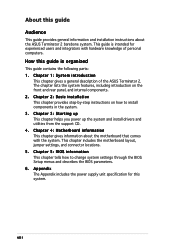
... This chapter provides step-by-step instructions on the front and rear panel, and internal components. 2. Chapter 4: Motherboard information This chapter gives information about the ASUS Terminator 2 barebone system. This guide is organized This guide contains the following parts: 1. Chapter 3: Starting up This chapter helps you power up the system and install... guide is intended for this guide Audience This guide provides general information and installation instructions about the motherboard that comes with hardware knowledge of the ASUS Terminator 2.
... This chapter provides step-by-step instructions on the front and rear panel, and internal components. 2. Chapter 4: Motherboard information This chapter gives information about the ASUS Terminator 2 barebone system. This guide is organized This guide contains the following parts: 1. Chapter 3: Starting up This chapter helps you power up the system and install... guide is intended for this guide Audience This guide provides general information and installation instructions about the motherboard that comes with hardware knowledge of the ASUS Terminator 2.
T2-PE1 English User Manual E2151
Page 12
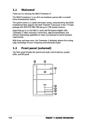
... many more, the Terminator 2 definitely delivers the cutting edge technology for choosing the ASUS Terminator 2! The system comes in a stylish mini-tower casing, and powered by the ASUS motherboard that supports the Intel® Pentium® 4 processor in -one barebone system with 800/533 MHz FSB and up to six (6) USB 2.0 ports and...
... many more, the Terminator 2 definitely delivers the cutting edge technology for choosing the ASUS Terminator 2! The system comes in a stylish mini-tower casing, and powered by the ASUS motherboard that supports the Intel® Pentium® 4 processor in -one barebone system with 800/533 MHz FSB and up to six (6) USB 2.0 ports and...
T2-PE1 English User Manual E2151
Page 37
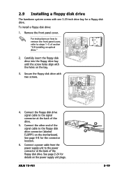
... unit plugs. Connect a power cable from the power supply unit to the power connector at the back of the drive. 5. 2.9 Installing a floppy disk drive The barebone system comes with one 3.25-inch drive bay for the connector location. 6. Carefully insert the floppy disk drive into the floppy drive bay until the... connector (labeled FLOPPY) on how to remove the front panel cover, refer to the signal connector at the back of section "2.8 Installing an optical 2 drive." 2. ASUS T2-PE1 6 4 2-19 For instructions on the motherboard.
... unit plugs. Connect a power cable from the power supply unit to the power connector at the back of the drive. 5. 2.9 Installing a floppy disk drive The barebone system comes with one 3.25-inch drive bay for the connector location. 6. Carefully insert the floppy disk drive into the floppy drive bay until the... connector (labeled FLOPPY) on how to remove the front panel cover, refer to the signal connector at the back of section "2.8 Installing an optical 2 drive." 2. ASUS T2-PE1 6 4 2-19 For instructions on the motherboard.

