
User Guide
Page 12
... introduction See the figure below. 1.1 System package contents Check your system package for the following items. Model Name Chassis RS520-E6/RS8 ASUS R20A 2U Rackmount Chassis Motherboard ASUS Z8NR-D12-SYS Server Board Component 1 x 770W Redundant Power Supply 1 x SATAII/SAS HDD Backplane (BP8LX-R20A) 8 x hot-swap HDD trays (varies by territories) 1 x Front I/O Board (FPB-AR14) 4 x System...
... introduction See the figure below. 1.1 System package contents Check your system package for the following items. Model Name Chassis RS520-E6/RS8 ASUS R20A 2U Rackmount Chassis Motherboard ASUS Z8NR-D12-SYS Server Board Component 1 x 770W Redundant Power Supply 1 x SATAII/SAS HDD Backplane (BP8LX-R20A) 8 x hot-swap HDD trays (varies by territories) 1 x Front I/O Board (FPB-AR14) 4 x System...

User Guide
Page 15
... Expansion slots LAN port 2 LAN port 1 VGA port Serial port USB ports LAN port 3* PS/2 keyboard port PS/2 mouse port Power cord connector Redundant power supply dummy cover • The ports for the PS/2 keyboard, PS/2 mouse, USB, VGA, and Gigabit LAN do not appear on ... HDD 4 HDD 8 1.5 Rear panel features The rear panel includes the expansion slots, system power socket, and rear fans. Refer to section 1.7.1 Front panel LEDs for ASUS ASMB4-iKVM controller card only. ASUS RS520-E6/RS8 1-5 The power and reset buttons, LED indicators, optical drive, and two USB ports are located on the ...
... Expansion slots LAN port 2 LAN port 1 VGA port Serial port USB ports LAN port 3* PS/2 keyboard port PS/2 mouse port Power cord connector Redundant power supply dummy cover • The ports for the PS/2 keyboard, PS/2 mouse, USB, VGA, and Gigabit LAN do not appear on ... HDD 4 HDD 8 1.5 Rear panel features The rear panel includes the expansion slots, system power socket, and rear fans. Refer to section 1.7.1 Front panel LEDs for ASUS ASMB4-iKVM controller card only. ASUS RS520-E6/RS8 1-5 The power and reset buttons, LED indicators, optical drive, and two USB ports are located on the ...

User Guide
Page 27
... press the retaining clips outward to unplug the power supply before adding or removing DIMMs or other system components. Failure to do so may cause severe damage to remove a DIMM. 2 1. Align a DIMM on the socket. 2 DIMM notch 1 1 Unlocked retaining clip A DIMM is properly seated. ASUS RS520-E6/RS8 2-9 DO NOT force a DIMM into the socket until...
... press the retaining clips outward to unplug the power supply before adding or removing DIMMs or other system components. Failure to do so may cause severe damage to remove a DIMM. 2 1. Align a DIMM on the socket. 2 DIMM notch 1 1 Unlocked retaining clip A DIMM is properly seated. ASUS RS520-E6/RS8 2-9 DO NOT force a DIMM into the socket until...

User Guide
Page 33
2.7 SATAII/SAS backplane cabling Connects a 8-pin plug from power supply Connects the data cables connected to the motherboard SGPIO_SEL jumper: pins 1-2 (Onboard) pins 2-3 (Add-on card) ASUS RS520-E6/RS8 2-15
2.7 SATAII/SAS backplane cabling Connects a 8-pin plug from power supply Connects the data cables connected to the motherboard SGPIO_SEL jumper: pins 1-2 (Onboard) pins 2-3 (Add-on card) ASUS RS520-E6/RS8 2-15

User Guide
Page 37
ASUS RS520-E6/RS8 2-19 Take out the seocond redundant power supply module from its package. Firmly pull the lever to slide the power supply module into the chassis. 3. Slide it into the chassis. 2.8.3 Redundant power supply module To install a second redundant power supply module: 1. Remove the redundant power supply dummy cover. 2.
ASUS RS520-E6/RS8 2-19 Take out the seocond redundant power supply module from its package. Firmly pull the lever to slide the power supply module into the chassis. 3. Slide it into the chassis. 2.8.3 Redundant power supply module To install a second redundant power supply module: 1. Remove the redundant power supply dummy cover. 2.

User Guide
Page 47
...RAM (CLRTC1) 2. LAN controller setting (3-pin LAN_SW1, LAN_SW2) 4. Hard disk activity LED connector (4-pin HDLED1) 4. USB connectors (10-1 pin USB34, USB56; 4-pin USB7) 7. SSI power ...ASUS RS520-E6/RS8 4-3 Serial General Purpose Input/Output connector (6-1 pin SGPIO1) 5. DDR3 voltage setting (4-pin LVDDR3_SEL1/2) Page 4-4 4-5 4-5 4-6 4-6 4-7 4-7 4-8 4-8 Internal connectors 1. Layout contents Jumpers 1. VGA controller setting (3-pin VGA_SW1) 3. SAS connectors (7-pin SAS1-4 [red], SAS5-8 [blue]) 3. System panel connector (20-1 pin PANEL1 [white]) 13. Power supply...
...RAM (CLRTC1) 2. LAN controller setting (3-pin LAN_SW1, LAN_SW2) 4. Hard disk activity LED connector (4-pin HDLED1) 4. USB connectors (10-1 pin USB34, USB56; 4-pin USB7) 7. SSI power ...ASUS RS520-E6/RS8 4-3 Serial General Purpose Input/Output connector (6-1 pin SGPIO1) 5. DDR3 voltage setting (4-pin LVDDR3_SEL1/2) Page 4-4 4-5 4-5 4-6 4-6 4-7 4-7 4-8 4-8 Internal connectors 1. Layout contents Jumpers 1. VGA controller setting (3-pin VGA_SW1) 3. SAS connectors (7-pin SAS1-4 [red], SAS5-8 [blue]) 3. System panel connector (20-1 pin PANEL1 [white]) 13. Power supply...
User Guide
Page 57
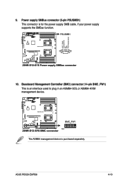
Power supply SMBus connector (5-pin PSUSMB1) This connector is purchased separately. ASUS RS520-E6/RS8 4-13 The ASMB4 management device is for the power supply SMB cable, if your power supply supports the SMBus function. 10. Baseboard Management Controller (BMC) connector (14-pin BMC_FW1) This is an interface used to plug in an ASMB4-SOL or ASMB4-iKVM management device. 9.
Power supply SMBus connector (5-pin PSUSMB1) This connector is purchased separately. ASUS RS520-E6/RS8 4-13 The ASMB4 management device is for the power supply SMB cable, if your power supply supports the SMBus function. 10. Baseboard Management Controller (BMC) connector (14-pin BMC_FW1) This is an interface used to plug in an ASMB4-SOL or ASMB4-iKVM management device. 9.


