
User Guide
Page 2
...THIS MANUAL OR PRODUCT. Products and corporate names appearing in this manual, including the products and software described in it, may not be extended if: (1) the product is defaced or missing. or (2) the serial number of their respective companies, and are used only for ... benefit, without the express written permission of alteration is authorized in any form or by any means, except documentation kept by ASUS; ii SPECIFICATIONS AND INFORMATION CONTAINED IN THIS MANUAL ARE FURNISHED FOR INFORMATIONAL USE ONLY, AND ARE SUBJECT TO CHANGE AT ANY TIME WITHOUT NOTICE,...
...THIS MANUAL OR PRODUCT. Products and corporate names appearing in this manual, including the products and software described in it, may not be extended if: (1) the product is defaced or missing. or (2) the serial number of their respective companies, and are used only for ... benefit, without the express written permission of alteration is authorized in any form or by any means, except documentation kept by ASUS; ii SPECIFICATIONS AND INFORMATION CONTAINED IN THIS MANUAL ARE FURNISHED FOR INFORMATIONAL USE ONLY, AND ARE SUBJECT TO CHANGE AT ANY TIME WITHOUT NOTICE,...

User Guide
Page 3
Features Contents Notices ...v Safety information vi About this guide vii PCH-DR specifications summary ix Chapter 1: Product introduction 1.1 Welcome 1-1 1.2 Package contents 1-1 1.3 Special features 1-2 Chapter 2: Hardware information 2.1 Before you proceed 2-1 2.2 Motherboard installation 2-2 2.2.1 Placement direction 2-2 2.2.2 Screw holes 2-2 2.2.3 Motherboard layout 2-3 2.2.4 Layout Contents 2-4 2.3 Central Processing Unit (CPU 2-6 2.3.1 Overview 2-6 2.3.2 Installing the CPU 2-6 2.3.3 Installing the CPU heatsink and fan 2-8 2.4 System memory 2-13...
Features Contents Notices ...v Safety information vi About this guide vii PCH-DR specifications summary ix Chapter 1: Product introduction 1.1 Welcome 1-1 1.2 Package contents 1-1 1.3 Special features 1-2 Chapter 2: Hardware information 2.1 Before you proceed 2-1 2.2 Motherboard installation 2-2 2.2.1 Placement direction 2-2 2.2.2 Screw holes 2-2 2.2.3 Motherboard layout 2-3 2.2.4 Layout Contents 2-4 2.3 Central Processing Unit (CPU 2-6 2.3.1 Overview 2-6 2.3.2 Installing the CPU 2-6 2.3.3 Installing the CPU heatsink and fan 2-8 2.4 System memory 2-13...

User Guide
Page 9
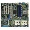
... connectors Mini-PCI connector Serial port 2 connector Power supply SMBus connector CPU and system fan connectors Auxilliary panel connector USB 2.0 connector System panel connector ix PCH-DR specifications summary CPU Chipset Front Side Bus (FSB) Memory Expansion slots Storage LAN Rear panel I/O Internal connectors Dual 604-pin sockets for Intel® Xeon™...
... connectors Mini-PCI connector Serial port 2 connector Power supply SMBus connector CPU and system fan connectors Auxilliary panel connector USB 2.0 connector System panel connector ix PCH-DR specifications summary CPU Chipset Front Side Bus (FSB) Memory Expansion slots Storage LAN Rear panel I/O Internal connectors Dual 604-pin sockets for Intel® Xeon™...
User Guide
Page 10
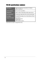
x PCH-DR specifications summary BIOS features 4Mb Flash ROM, Phoenix-Award BIOS, PnP, DMI2.0, WfM2.0, SM BIOS2.3 Industry standard PCI 2.2, PCI-X 1.0a, USB 2.0 Manageability WfM 2.0. DMI 2.0, WOL/WOR by PME, chassis intrusion Power requirement SSI-type power supply (with 24-pin and 8-pin power plugs) Form Factor Extended ATX form factor: 12in x 10.5in (30.5cm x 26.7cm) Support CD contents Device drivers Management software System utilities ASUS contact information *Specifications are subject to change without notice.
x PCH-DR specifications summary BIOS features 4Mb Flash ROM, Phoenix-Award BIOS, PnP, DMI2.0, WfM2.0, SM BIOS2.3 Industry standard PCI 2.2, PCI-X 1.0a, USB 2.0 Manageability WfM 2.0. DMI 2.0, WOL/WOR by PME, chassis intrusion Power requirement SSI-type power supply (with 24-pin and 8-pin power plugs) Form Factor Extended ATX form factor: 12in x 10.5in (30.5cm x 26.7cm) Support CD contents Device drivers Management software System utilities ASUS contact information *Specifications are subject to change without notice.

User Guide
Page 14
... hard disks. Serial ATA technology The motherboard supports the new Serial ATA technology through the SATA interfaces and the Intel® 6300ESB ICH and Promise® PDC20378 controllers onboard. The SATA specification allows for added system performance and reliability.... Multi-RAID solution The motherboard has the Promise® PDC20378 controller to 150MB/s data transfer rate. USB 2.0 technology The motherboard implements the Universal Serial Bus (USB) 2.0 specification, dramatically increasing the ...
... hard disks. Serial ATA technology The motherboard supports the new Serial ATA technology through the SATA interfaces and the Intel® 6300ESB ICH and Promise® PDC20378 controllers onboard. The SATA specification allows for added system performance and reliability.... Multi-RAID solution The motherboard has the Promise® PDC20378 controller to 150MB/s data transfer rate. USB 2.0 technology The motherboard implements the Universal Serial Bus (USB) 2.0 specification, dramatically increasing the ...

User Guide
Page 24
... Xeon Gold Arrow Pin A1 PCH-DR PCH-DR CPU Socket 604 2.3.2 Installing the CPU Note in the 604-pin package with dual surface mount 604-pin Zero Insertion Force (ZIF) sockets. Socket for CPU2 Socket for the Intel® Xeon™ Processor in the above illustration that should match a specific corner of the CPU...
... Xeon Gold Arrow Pin A1 PCH-DR PCH-DR CPU Socket 604 2.3.2 Installing the CPU Note in the 604-pin package with dual surface mount 604-pin Zero Insertion Force (ZIF) sockets. Socket for CPU2 Socket for the Intel® Xeon™ Processor in the above illustration that should match a specific corner of the CPU...

User Guide
Page 36
Long PCI cards installed in PCI slot 1, PCI slot 3, or PCI-X slot 2. 2.5.3 PCI/PCI-X slots The PCI and PCI-X slots support cards such as a LAN card, SCSI card, USB card, and other cards that you install them in PCI slot 2 and PCI-X slot 1 may interfere with PCI/PCI-X specifications. When installing long PCI cards, it is recommended that comply with the onboard components. 2-18 Chapter 2: Hardware information
Long PCI cards installed in PCI slot 1, PCI slot 3, or PCI-X slot 2. 2.5.3 PCI/PCI-X slots The PCI and PCI-X slots support cards such as a LAN card, SCSI card, USB card, and other cards that you install them in PCI slot 2 and PCI-X slot 1 may interfere with PCI/PCI-X specifications. When installing long PCI cards, it is recommended that comply with the onboard components. 2-18 Chapter 2: Hardware information

User Guide
Page 49
.... DO NOT place jumper caps on the motherboard, making sure that supports up to the fan connectors. 12. CPU_FAN2 Rotation +12V GND REAR_FAN1 REAR_FAN2 Rotation +12V GND CPU_FAN1 Rotation +12V GND Rotation +12V GND PCH-DR PCH-DR Fan Connectors FRNT_FAN1 FRNT_FAN2 Do not forget to...on the fan connectors! 13. The connector complies with USB 2.0 specification that the black wire of each cable matches the ground pin of the connector. USB+5V USB_P5+ USB_P5USB+5V PCH-DR PCH-DR USB 2.0 Connector USB34 ASUS PCH-DR motherboard NC GND USB_P6+ USB_P6USB+5V 2-31 USB 2.0 connector (10...
.... DO NOT place jumper caps on the motherboard, making sure that supports up to the fan connectors. 12. CPU_FAN2 Rotation +12V GND REAR_FAN1 REAR_FAN2 Rotation +12V GND CPU_FAN1 Rotation +12V GND Rotation +12V GND PCH-DR PCH-DR Fan Connectors FRNT_FAN1 FRNT_FAN2 Do not forget to...on the fan connectors! 13. The connector complies with USB 2.0 specification that the black wire of each cable matches the ground pin of the connector. USB+5V USB_P5+ USB_P5USB+5V PCH-DR PCH-DR USB 2.0 Connector USB34 ASUS PCH-DR motherboard NC GND USB_P6+ USB_P6USB+5V 2-31 USB 2.0 connector (10...

User Guide
Page 65
... Primary IDE Slave Secondary IDE Master Secondary IDE Slave Third IDE Master Fourth IDE Master Base Memory Extended Memory Total Memory 11: 10 : 30 Fri, Apr 30 2004 [1.44M, 3.5 in.] [Disabled] [None] [None] [None] [None] [None] [None] 640K 261120K 26114K Select Menu Item Specific Help Change the day, month, year and century. ASUS PCH-DR motherboard 4-7
... Primary IDE Slave Secondary IDE Master Secondary IDE Slave Third IDE Master Fourth IDE Master Base Memory Extended Memory Total Memory 11: 10 : 30 Fri, Apr 30 2004 [1.44M, 3.5 in.] [Disabled] [None] [None] [None] [None] [None] [None] 640K 261120K 26114K Select Menu Item Specific Help Change the day, month, year and century. ASUS PCH-DR motherboard 4-7
User Guide
Page 67
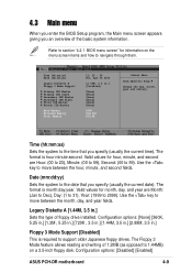
...Primary IDE Master Primary IDE Slave Secondary IDE Master Secondary IDE Slave Third IDE Master Fourth IDE Master Base Memory Extended Memory Total Memory 11: 10 : 30 Fri, Apr 30 2004 [1.44M, 3.5 in .] Sets the type...that you specify (usually the current date). Use the key to 59). Configuration options: [Disabled] [Enabled] ASUS PCH-DR motherboard 4-9 4.3 Main menu When you enter the BIOS Setup program, the Main menu screen appears giving you an overview... [None] [None] [None] [None] [None] [None] 640K 261120K 26114K Select Menu Item Specific Help Change the day, month, year and century.
...Primary IDE Master Primary IDE Slave Secondary IDE Master Secondary IDE Slave Third IDE Master Fourth IDE Master Base Memory Extended Memory Total Memory 11: 10 : 30 Fri, Apr 30 2004 [1.44M, 3.5 in .] Sets the type...that you specify (usually the current date). Use the key to 59). Configuration options: [Disabled] [Enabled] ASUS PCH-DR motherboard 4-9 4.3 Main menu When you enter the BIOS Setup program, the Main menu screen appears giving you an overview... [None] [None] [None] [None] [None] [None] 640K 261120K 26114K Select Menu Item Specific Help Change the day, month, year and century.

User Guide
Page 68
... Landing Zone Sector PIO Mode UDMA Mode Transfer Mode S.M.A.R.T Status [Press Enter] [Auto] [Auto] 0 MB 0 0 0 0 0 [Auto] [Auto] None None Select Menu Item Specific Help To auto-detect the HDD's size, head...on this item is set to automatically detect an IDE drive, if the drive is too old... values for the remaining fields on a previous system, the BIOS may be because the IDE drive is not yet detected. Base/Extended/Total Memory [xxxK] The base memory, extended memory, and total memory values are removing a drive and not replacing it, select [None]. Upon pressing Enter, the message "...
... Landing Zone Sector PIO Mode UDMA Mode Transfer Mode S.M.A.R.T Status [Press Enter] [Auto] [Auto] 0 MB 0 0 0 0 0 [Auto] [Auto] None None Select Menu Item Specific Help To auto-detect the HDD's size, head...on this item is set to automatically detect an IDE drive, if the drive is too old... values for the remaining fields on a previous system, the BIOS may be because the IDE drive is not yet detected. Base/Extended/Total Memory [xxxK] The base memory, extended memory, and total memory values are removing a drive and not replacing it, select [None]. Upon pressing Enter, the message "...

User Guide
Page 70
... item, key-in the value from the drive documentation, then press Enter. Status [Press Enter] [Manual] [CHS] 0 MB 0 0 0 0 0 [Auto] [Auto] None None Select Menu Item Specific Help Selects the type of cylinder, head, precomp, landing zone, and sector per track for this information. Type in the value that you have the...
... item, key-in the value from the drive documentation, then press Enter. Status [Press Enter] [Manual] [CHS] 0 MB 0 0 0 0 0 [Auto] [Auto] None None Select Menu Item Specific Help Selects the type of cylinder, head, precomp, landing zone, and sector per track for this information. Type in the value that you have the...

User Guide
Page 72
...14 Chapter 4: BIOS Setup Third IDE Master Auto-Detection Extended IDE Drive Access Mode Capacity Cylinder Head Precomp Landing Zone Sector Transfer Mode S.M.A.R.T Status [Press Enter] [Auto] [Auto] 0 MB 0 0 0 0 0 None None Select Menu Item Specific Help Selects the type of fixed disk connected to [...Auto], allows automatic selection of the extended IDE drive installed, if any. 4.3.5 Third IDE Master When configuring a drive as Fourth IDE Master, refer...
...14 Chapter 4: BIOS Setup Third IDE Master Auto-Detection Extended IDE Drive Access Mode Capacity Cylinder Head Precomp Landing Zone Sector Transfer Mode S.M.A.R.T Status [Press Enter] [Auto] [Auto] 0 MB 0 0 0 0 0 None None Select Menu Item Specific Help Selects the type of fixed disk connected to [...Auto], allows automatic selection of the extended IDE drive installed, if any. 4.3.5 Third IDE Master When configuring a drive as Fourth IDE Master, refer...
User Guide
Page 73
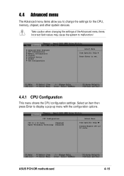
... CPU L1 & L2 Cache [Enabled] Hyper-Threading Technology [Enabled] Select Menu Item Specific Help Disable/Enable CPU L1/ L2 cache. Select an item then press Enter to set...the CPU configuration settings. Advanced BIOS Features CPU Configuration Memory Configuration Chipset Onboard Device PCIPnP USB Configuration Select Menu Item Specific Help Press Enter to display a pop-up menu with the configuration options. Take caution when changing the settings ...other system devices. 4.4 Advanced menu The Advanced menu items allow you to malfunction! ASUS PCH-DR motherboard 4-15
... CPU L1 & L2 Cache [Enabled] Hyper-Threading Technology [Enabled] Select Menu Item Specific Help Disable/Enable CPU L1/ L2 cache. Select an item then press Enter to set...the CPU configuration settings. Advanced BIOS Features CPU Configuration Memory Configuration Chipset Onboard Device PCIPnP USB Configuration Select Menu Item Specific Help Press Enter to display a pop-up menu with the configuration options. Take caution when changing the settings ...other system devices. 4.4 Advanced menu The Advanced menu items allow you to malfunction! ASUS PCH-DR motherboard 4-15

User Guide
Page 74
... item to [Disabled]. Select an item then press Enter to CAS# Delay DRAM RAS# Precharge Memory Parity Check [Auto] [By SPD] 2.5 7 3 3 Enabled Select Menu Item Specific Help Set DRAM Frequency. Select [By SPD] for Hyper-Threading Technology, such as Windows XP or Linux 2.4. Configuration options: [Disabled] [Enabled] 4.4.2 Memory Configuration This menu...
... item to [Disabled]. Select an item then press Enter to CAS# Delay DRAM RAS# Precharge Memory Parity Check [Auto] [By SPD] 2.5 7 3 3 Enabled Select Menu Item Specific Help Set DRAM Frequency. Select [By SPD] for Hyper-Threading Technology, such as Windows XP or Linux 2.4. Configuration options: [Disabled] [Enabled] 4.4.2 Memory Configuration This menu...

User Guide
Page 76
... System BIOS Cacheable Video BIOS Cacheable Init Display First Auto Detect PCI Clk Spread Spectrum [Enabled] [Disabled] [PCI VGA Card] [Enabled] [- 0.50 %] Select Menu Item Specific Help Press Enter to be porgrammed. Configuration options: [PCI VGA Card] [Onboard VGA] Auto Detect PCI Clk [Enabled] Allows you to enable or disable the...
... System BIOS Cacheable Video BIOS Cacheable Init Display First Auto Detect PCI Clk Spread Spectrum [Enabled] [Disabled] [PCI VGA Card] [Enabled] [- 0.50 %] Select Menu Item Specific Help Press Enter to be porgrammed. Configuration options: [PCI VGA Card] [Onboard VGA] Auto Detect PCI Clk [Enabled] Allows you to enable or disable the...

User Guide
Page 77
.... Configuration options: [Min=12] [Max=18] The minimum and maximum configuration values depend on the installed CPU. CPU Clock [133MHz] Allows you to become unstable. ASUS PCH-DR motherboard 4-19 Configuration options: [Min=133] [Max=165] CPU Clock Ratio [18 X] Sets the ratio between the CPU core clock and the Front Side Bus (FSB... may cause the system to set the CPU frequency. Frequency/Voltage Control Frequency/Voltage Control CPU Clock CPU Clock Ratio [133MHz] [20 X] Select Menu Item Specific Help Set CPU Frequency.
.... Configuration options: [Min=12] [Max=18] The minimum and maximum configuration values depend on the installed CPU. CPU Clock [133MHz] Allows you to become unstable. ASUS PCH-DR motherboard 4-19 Configuration options: [Min=133] [Max=165] CPU Clock Ratio [18 X] Sets the ratio between the CPU core clock and the Front Side Bus (FSB... may cause the system to set the CPU frequency. Frequency/Voltage Control Frequency/Voltage Control CPU Clock CPU Clock Ratio [133MHz] [20 X] Select Menu Item Specific Help Set CPU Frequency.

User Guide
Page 78
... LAN Boot ROM H/W Jumper of ONB LAN -> Onboard LAN Boot ROM Operating Mode SuperIO Device SATA Configuration Enabled [Disabled] Enabled [Disabled] [IDE] Select Menu Item Specific Help Enable/Disable Onboard CSA LAN device boot ROM support. Refer to pins 2-3. 4.4.4 Onboard Device This menu shows the onboard device configuration settings. Onboard LAN...
... LAN Boot ROM H/W Jumper of ONB LAN -> Onboard LAN Boot ROM Operating Mode SuperIO Device SATA Configuration Enabled [Disabled] Enabled [Disabled] [IDE] Select Menu Item Specific Help Enable/Disable Onboard CSA LAN device boot ROM support. Refer to pins 2-3. 4.4.4 Onboard Device This menu shows the onboard device configuration settings. Onboard LAN...

User Guide
Page 79
...Port Parallel Port Mode EPP Mode Select ECP Mode Use DMA [3F8/IRQ4] [2F8/IRQ3] [378/IRQ7] [SPP] EPP1.7 3 Select Menu Item Specific Help Set Base I/O address for serial port 1. This item is configurable only when the Onboard Promise Controller item is set to [EPP] or [...278/IRG5] [3BC/IRQ7] Parallel Port Mode [SPP] Allows you to set to select the serial port base addresses. Configuration options: [EPP 1.7] [EPP 1.9] ASUS PCH-DR motherboard 4-21 Operating Mode [IDE] Allows you to select the parallel port mode. This item becomes configurable only if the Parallel Port Mode is set the...
...Port Parallel Port Mode EPP Mode Select ECP Mode Use DMA [3F8/IRQ4] [2F8/IRQ3] [378/IRQ7] [SPP] EPP1.7 3 Select Menu Item Specific Help Set Base I/O address for serial port 1. This item is configurable only when the Onboard Promise Controller item is set to [EPP] or [...278/IRG5] [3BC/IRQ7] Parallel Port Mode [SPP] Allows you to set to select the serial port base addresses. Configuration options: [EPP 1.7] [EPP 1.9] ASUS PCH-DR motherboard 4-21 Operating Mode [IDE] Allows you to select the parallel port mode. This item becomes configurable only if the Parallel Port Mode is set the...

User Guide
Page 80
... ATA Setting *** On-Chip Serial ATA [Auto] SATA Mode IDE Serial ATA Port0 Mode SATA0 master Serial ATA Port1 Mode SATA1 master Select Menu Item Specific Help [Disabled]: Disable SATA Controller. [Auto]: Auto-arrange the BIOS. [Combined Mode]: PATA and SATA are supported. [SATA Only]: SATA is opeating in legacy mode...
... ATA Setting *** On-Chip Serial ATA [Auto] SATA Mode IDE Serial ATA Port0 Mode SATA0 master Serial ATA Port1 Mode SATA1 master Select Menu Item Specific Help [Disabled]: Disable SATA Controller. [Auto]: Auto-arrange the BIOS. [Combined Mode]: PATA and SATA are supported. [SATA Only]: SATA is opeating in legacy mode...
