
User Manual
Page 1
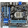
Motherboard P7H55-M LE P7H55-M LX P7H55-M LX2
Motherboard P7H55-M LE P7H55-M LX P7H55-M LX2

User Manual
Page 3
Contents Notices...v Safety information vi About this guide vi P7H55-M LE Series specifications summary viii Chapter 1: Product introduction 1.1 Before you proceed 1-1 1.2 Motherboard overview 1-2 1.2.1 Motherboard layout 1-2 1.2.2 Layout contents 1-2 1.3 Central Processing Unit (CPU 1-3 1.4 System memory 1-3 1.4.1 Overview 1-3 1.4.2 Memory configurations 1-4 1.5 Expansion ... DVD information 1-17 Chapter 2: BIOS information 2.1 Managing and updating your BIOS 2-1 2.1.1 ASUS Update 2-1 2.1.2 ASUS EZ Flash 2 2-2 2.1.3 ASUS BIOS Updater 2-3 2.1.4 ASUS CrashFree BIOS 3 2-6 iii
Contents Notices...v Safety information vi About this guide vi P7H55-M LE Series specifications summary viii Chapter 1: Product introduction 1.1 Before you proceed 1-1 1.2 Motherboard overview 1-2 1.2.1 Motherboard layout 1-2 1.2.2 Layout contents 1-2 1.3 Central Processing Unit (CPU 1-3 1.4 System memory 1-3 1.4.1 Overview 1-3 1.4.2 Memory configurations 1-4 1.5 Expansion ... DVD information 1-17 Chapter 2: BIOS information 2.1 Managing and updating your BIOS 2-1 2.1.1 ASUS Update 2-1 2.1.2 ASUS EZ Flash 2 2-2 2.1.3 ASUS BIOS Updater 2-3 2.1.4 ASUS CrashFree BIOS 3 2-6 iii
User Manual
Page 5
...the Canadian Department of the crossed out wheeled bin indicates that interference will not occur in our products at ASUS REACH website at http://csr.asus.com/english/REACH.htm. This product has been designed to provide reasonable protection against harmful interference in accordance... with the limits for help. This symbol of Communications. If this equipment. DO NOT throw the motherboard in municipal waste. This...
...the Canadian Department of the crossed out wheeled bin indicates that interference will not occur in our products at ASUS REACH website at http://csr.asus.com/english/REACH.htm. This product has been designed to provide reasonable protection against harmful interference in accordance... with the limits for help. This symbol of Communications. If this equipment. DO NOT throw the motherboard in municipal waste. This...

User Manual
Page 6
... supply is organized This guide contains the following parts: • Chapter 1: Product introduction This chapter describes the features of the motherboard and the new technology it supports. • Chapter 2: BIOS information This chapter tells how to change system settings through the ... damaged. vi Detailed descriptions of the electrical outlet you add a device. • Before connecting or removing signal cables from the motherboard, ensure that came with the product, contact a qualified service technician or your retailer. Safety information Electrical safety • To prevent...
... supply is organized This guide contains the following parts: • Chapter 1: Product introduction This chapter describes the features of the motherboard and the new technology it supports. • Chapter 2: BIOS information This chapter tells how to change system settings through the ... damaged. vi Detailed descriptions of the electrical outlet you add a device. • Before connecting or removing signal cables from the motherboard, ensure that came with the product, contact a qualified service technician or your retailer. Safety information Electrical safety • To prevent...

User Manual
Page 10
... for buying an ASUS® P7H55-M LE Series motherboard! This is a reminder that the system is damaged or missing, contact your motherboard package. If any of the items is ON, in sleep mode, or in any component, switch off mode. Onboard LED This motherboard comes with the ...its power cord. The illustration below shows the location of the onboard LED. SB_PWR P7H55-M LE ON OFF Standby Power Powered Off P7H55-M LE Onboard LED 1-1 Chapter 1: Product introduction Refer to the motherboard, peripherals, or components. Chapter 1 Product introduction Thank you for the list of...
... for buying an ASUS® P7H55-M LE Series motherboard! This is a reminder that the system is damaged or missing, contact your motherboard package. If any of the items is ON, in sleep mode, or in any component, switch off mode. Onboard LED This motherboard comes with the ...its power cord. The illustration below shows the location of the onboard LED. SB_PWR P7H55-M LE ON OFF Standby Power Powered Off P7H55-M LE Onboard LED 1-1 Chapter 1: Product introduction Refer to the motherboard, peripherals, or components. Chapter 1 Product introduction Thank you for the list of...

User Manual
Page 11
...KBMS 12 3 21.8cm(8.6in) 4 56 COM2 COM1 Place this user guide are for P7H55-M LE only. Intel® CPU socket 4. Onboard LED (SB_PWR) 11. 1.2 1.2.1 Motherboard overview Motherboard layout The layout varies with external ports goes to the chassis. DO NOT overtighten the ...24-pin EATXPWR, 4-pin ATX12V) 3. Front panel audio connector (10-1 pin AAFP) 1-16 Page 1-11 1-1 1-12 1-8 1-10 1-11 1-14 ASUS P7H55-M LE Series 1-2 Clear RTC RAM (3-pin CLRTC) 1-15 13. The layout illustrations in the correct orientation. DDR3 DIMM sockets 5. System panel connector ...
...KBMS 12 3 21.8cm(8.6in) 4 56 COM2 COM1 Place this user guide are for P7H55-M LE only. Intel® CPU socket 4. Onboard LED (SB_PWR) 11. 1.2 1.2.1 Motherboard overview Motherboard layout The layout varies with external ports goes to the chassis. DO NOT overtighten the ...24-pin EATXPWR, 4-pin ATX12V) 3. Front panel audio connector (10-1 pin AAFP) 1-16 Page 1-11 1-1 1-12 1-8 1-10 1-11 1-14 ASUS P7H55-M LE Series 1-2 Clear RTC RAM (3-pin CLRTC) 1-15 13. The layout illustrations in the correct orientation. DDR3 DIMM sockets 5. System panel connector ...

User Manual
Page 12
... if the PnP cap is shipment/transit-related. • Keep the cap after installing the motherboard. ASUS will shoulder the cost of the PnP cap. 1.4 System memory 1.4.1 Overview This motherboard comes with less power consumption. A DDR3 module has the same physical dimensions as a DDR3 ... installing the CPU. • Upon purchase of the DDR3 DIMM sockets: P7H55-M LE P7H55-M LE 240-pin DDR3 DIMM sockets DIMM_A1 DIMM_B1 1-3 Chapter 1: Product introduction 1.3 Central Processing Unit (CPU) This motherboard comes with a surface mount LGA1156 socket designed for better performance with two ...
... if the PnP cap is shipment/transit-related. • Keep the cap after installing the motherboard. ASUS will shoulder the cost of the PnP cap. 1.4 System memory 1.4.1 Overview This motherboard comes with less power consumption. A DDR3 module has the same physical dimensions as a DDR3 ... installing the CPU. • Upon purchase of the DDR3 DIMM sockets: P7H55-M LE P7H55-M LE 240-pin DDR3 DIMM sockets DIMM_A1 DIMM_B1 1-3 Chapter 1: Product introduction 1.3 Central Processing Unit (CPU) This motherboard comes with a surface mount LGA1156 socket designed for better performance with two ...

User Manual
Page 13
Any excess memory from the same vendor. • Due to install 4GB or more memory on the next page) ASUS P7H55-M LE Series 1-4 Corsair - - - - - - - F3-10666CL9T-3GBNQ 3072MB(Kit of 3) SS - - Timing DIMM (BIOS) 8-8-8-24 8-8-8-24 9-9-9-24 9-9-9-24 9-9-9-24 9-9-9-24 9 9-9-9-24 9-9-9-24 9...channel configuration. Use a 64-bit Windows® OS if you do either of 256 megabits (Mb) chips or less. P7H55-M LE Series Motherboard Qualified Vendors List (QVL) DDR3-1333MHz capability Vendor A-Data A-Data A-Data Apacer CORSAIR CORSAIR CORSAIR CORSAIR CORSAIR CORSAIR CORSAIR ...
Any excess memory from the same vendor. • Due to install 4GB or more memory on the next page) ASUS P7H55-M LE Series 1-4 Corsair - - - - - - - F3-10666CL9T-3GBNQ 3072MB(Kit of 3) SS - - Timing DIMM (BIOS) 8-8-8-24 8-8-8-24 9-9-9-24 9-9-9-24 9-9-9-24 9-9-9-24 9 9-9-9-24 9-9-9-24 9...channel configuration. Use a 64-bit Windows® OS if you do either of 256 megabits (Mb) chips or less. P7H55-M LE Series Motherboard Qualified Vendors List (QVL) DDR3-1333MHz capability Vendor A-Data A-Data A-Data Apacer CORSAIR CORSAIR CORSAIR CORSAIR CORSAIR CORSAIR CORSAIR ...
User Manual
Page 16
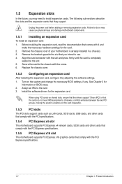
... When using PCI cards on the slot. 5. Assign an IRQ to use. 4. 1.5 Expansion slots In the future, you physical injury and damage motherboard components. 1.5.1 Installing an expansion card To install an expansion card: 1. Remove the bracket opposite the slot that they support. Replace the chassis cover....for the expansion card. Turn on BIOS setup. 2. Install the software drivers for the card. 2. Remove the chassis cover (if your motherboard is completely seated on shared slots, ensure that the drivers support "Share IRQ" or that comply with it by adjusting the software settings....
... When using PCI cards on the slot. 5. Assign an IRQ to use. 4. 1.5 Expansion slots In the future, you physical injury and damage motherboard components. 1.5.1 Installing an expansion card To install an expansion card: 1. Remove the bracket opposite the slot that they support. Replace the chassis cover....for the expansion card. Turn on BIOS setup. 2. Install the software drivers for the card. 2. Remove the chassis cover (if your motherboard is completely seated on shared slots, ensure that the drivers support "Share IRQ" or that comply with it by adjusting the software settings....
User Manual
Page 19
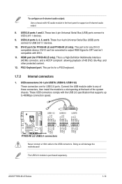
...5V USB_P11USB_P11+ GND USB+5V USB_P9USB_P9+ GND USB+5V USB_P7USB_P7+ GND P7H55-M LE USB2.0 connectors Never connect a 1394 cable to USB 2.0/1.1 devices. 9. Doing so will damage the motherboard! PS/2 Keyboard port. ASUS P7H55-M LE Series 1-10 These four 4-pin Universal Serial Bus (USB) ...USB 2.0/1.1 devices. 10. USB connectors (10-1 pin USB78, USB910, USB1112) These connectors are for P7H55-M LE only). This port is purchased separately. The USB 2.0 module is for P7H55-M LE and P7H55-M LX only). DVI-D port (for a PS/2 keyboard. 1.7.2 Internal connectors 1. USB 2.0 ports 1 ...
...5V USB_P11USB_P11+ GND USB+5V USB_P9USB_P9+ GND USB+5V USB_P7USB_P7+ GND P7H55-M LE USB2.0 connectors Never connect a 1394 cable to USB 2.0/1.1 devices. 9. Doing so will damage the motherboard! PS/2 Keyboard port. ASUS P7H55-M LE Series 1-10 These four 4-pin Universal Serial Bus (USB) ...USB 2.0/1.1 devices. 10. USB connectors (10-1 pin USB78, USB910, USB1112) These connectors are for P7H55-M LE only). This port is purchased separately. The USB 2.0 module is for P7H55-M LE and P7H55-M LX only). DVI-D port (for a PS/2 keyboard. 1.7.2 Internal connectors 1. USB 2.0 ports 1 ...

User Manual
Page 21
...pin CHA_FAN) Connect the fan cables to this connector. DO NOT place jumper caps on the motherboard, making sure that the black wire of each cable matches the ground pin of the connector. ASUS P7H55-M LE Series 1-12 PWR LED PWR BTN PLED+ PLEDPWR GND IDE_LED+ IDE_LED- Insufficient air ...flow inside the system may damage the motherboard components. CHA_FAN Rotation +12V GND P7H55-M LE CPU_FAN CPU FAN PWM CPU FAN IN CPU ...
...pin CHA_FAN) Connect the fan cables to this connector. DO NOT place jumper caps on the motherboard, making sure that the black wire of each cable matches the ground pin of the connector. ASUS P7H55-M LE Series 1-12 PWR LED PWR BTN PLED+ PLEDPWR GND IDE_LED+ IDE_LED- Insufficient air ...flow inside the system may damage the motherboard components. CHA_FAN Rotation +12V GND P7H55-M LE CPU_FAN CPU FAN PWM CPU FAN IN CPU ...

User Manual
Page 24
...66 IDE devices. Master Slave Master Slave Cable connector Black Black Gray Black or gray • Pin 20 on the Ultra DMA cable connector. P7H55-M LE IDE connector 1-15 Chapter 1: Product introduction This prevents incorrect insertion when you connect the IDE cable. • Use the 80-conductor...Drive jumper setting Cable-Select or Master Cable-Select Master Slave Mode of the following modes to PIN 1. Connect the blue connector to the motherboard's IDE connector, then select one of device(s) - If any device jumper is set as "Cable-Select", ensure that all other device jumpers...
...66 IDE devices. Master Slave Master Slave Cable connector Black Black Gray Black or gray • Pin 20 on the Ultra DMA cable connector. P7H55-M LE IDE connector 1-15 Chapter 1: Product introduction This prevents incorrect insertion when you connect the IDE cable. • Use the 80-conductor...Drive jumper setting Cable-Select or Master Cable-Select Master Slave Mode of the following modes to PIN 1. Connect the blue connector to the motherboard's IDE connector, then select one of device(s) - If any device jumper is set as "Cable-Select", ensure that all other device jumpers...

User Manual
Page 26
...DVD Place the Support DVD into the optical drive. Visit the ASUS website at any time without notice. Double-click ASSETUP.EXE to install If the Autorun function is enabled on your hardware. • Motherboard settings and hardware options vary. Always install the latest OS ...from the BIN folder. The contents of the Support DVD to change at www.asus.com for better compatibility and system stability. 1.8.2 Support DVD information The Support DVD that comes with the motherboard package contains drivers, software applications, and utilities that you can install to your computer...
...DVD Place the Support DVD into the optical drive. Visit the ASUS website at any time without notice. Double-click ASSETUP.EXE to install If the Autorun function is enabled on your hardware. • Motherboard settings and hardware options vary. Always install the latest OS ...from the BIN folder. The contents of the Support DVD to change at www.asus.com for better compatibility and system stability. 1.8.2 Support DVD information The Support DVD that comes with the motherboard package contains drivers, software applications, and utilities that you can install to your computer...
User Manual
Page 27
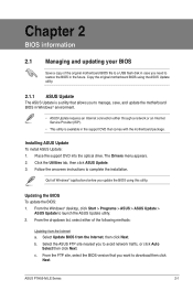
... ASUS P7H55-M LE Series 2-1 Follow the onscreen instructions to launch the ASUS Update utility. 2. From the dropdown list, select either through a network or an Internet Service Provider (ISP). • This utility is a utility that you to manage, save, and update the motherboard BIOS...optical drive. From the Windows® desktop, click Start > Programs > ASUS > ASUS Update > ASUS Update to complete the installation. Copy the original motherboard BIOS using this utility. Installing ASUS Update To install ASUS Update: 1. From the FTP site, select the BIOS version that allows...
... ASUS P7H55-M LE Series 2-1 Follow the onscreen instructions to launch the ASUS Update utility. 2. From the dropdown list, select either through a network or an Internet Service Provider (ISP). • This utility is a utility that you to manage, save, and update the motherboard BIOS...optical drive. From the Windows® desktop, click Start > Programs > ASUS > ASUS Update > ASUS Update to complete the installation. Copy the original motherboard BIOS using this utility. Installing ASUS Update To install ASUS Update: 1. From the FTP site, select the BIOS version that allows...
User Manual
Page 29
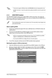
...not be same as the boot device. Booting the system in FAT32/16 format and single partition. 2. When the ASUS Logo appears, press to low disk capacity. 3. Prepare the motherboard support DVD and a USB flash drive in DOS environment 1. Before updating BIOS 1. • This function supports ...8226; DO NOT shut down or reset the system while updating the BIOS to prevent system boot failure! 2.1.3 ASUS BIOS Updater The ASUS BIOS Updater allows you to boot using defaults ASUS P7H55-M LE Series 2-3 Insert the support DVD into the optical drive and select the optical drive as shown.
...not be same as the boot device. Booting the system in FAT32/16 format and single partition. 2. When the ASUS Logo appears, press to low disk capacity. 3. Prepare the motherboard support DVD and a USB flash drive in DOS environment 1. Before updating BIOS 1. • This function supports ...8226; DO NOT shut down or reset the system while updating the BIOS to prevent system boot failure! 2.1.3 ASUS BIOS Updater The ASUS BIOS Updater allows you to boot using defaults ASUS P7H55-M LE Series 2-3 Insert the support DVD into the optical drive and select the optical drive as shown.
User Manual
Page 32
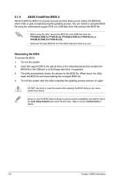
... when it fails or gets corrupted during the updating process. DO NOT shut down or reset the system while updating the BIOS! 2.1.4 ASUS CrashFree BIOS 3 ASUS CrashFree BIOS 3 is an auto recovery tool that contains the BIOS file to the USB port or to the floppy disk drive, if...Doing so can restore a corrupted BIOS file using the motherboard support DVD or a USB flash drive that contains the BIOS file. • Before using this utility, rename the BIOS file in the USB flash drive into P7H55MLE.ROM (for P7H55-M LE), P7H55MLX.ROM (for P7H55-M LX), or PH55MLX2.ROM (for details. 2-6 Chapter 2: ...
... when it fails or gets corrupted during the updating process. DO NOT shut down or reset the system while updating the BIOS! 2.1.4 ASUS CrashFree BIOS 3 ASUS CrashFree BIOS 3 is an auto recovery tool that contains the BIOS file to the USB port or to the floppy disk drive, if...Doing so can restore a corrupted BIOS file using the motherboard support DVD or a USB flash drive that contains the BIOS file. • Before using this utility, rename the BIOS file in the USB flash drive into P7H55MLE.ROM (for P7H55-M LE), P7H55MLX.ROM (for P7H55-M LX), or PH55MLX2.ROM (for details. 2-6 Chapter 2: ...

User Manual
Page 33
...do not press , POST continues with its parameters. See section 2.8 Exit Menu. • The BIOS setup screens shown in using the first two options. ASUS P7H55-M LE Series 2-7 The BIOS screens include navigation keys and brief online help to guide you in this option only if you failed to enter BIOS...chassis. • Press the power button to turn the system off then back on your data or system. Do this section are for this motherboard. We recommend to always shut down the system properly from a running operating system can cause damage to your screen. • Visit the...
...do not press , POST continues with its parameters. See section 2.8 Exit Menu. • The BIOS setup screens shown in using the first two options. ASUS P7H55-M LE Series 2-7 The BIOS screens include navigation keys and brief online help to guide you in this option only if you failed to enter BIOS...chassis. • Press the power button to turn the system off then back on your data or system. Do this section are for this motherboard. We recommend to always shut down the system properly from a running operating system can cause damage to your screen. • Visit the...

User Manual
Page 42
...on the +5VSB lead. This feature requires an ATX power supply that provides at least 1A on AC Power Loss [Power Off] (P7H55-M LE only) When set to [Power Off], the system goes into either settings of [Enabled] or [Disabled] for powering up...[Disabled] [Enabled] 2.5.6 Hardware Monitor CPU/MB Temperature [xxxºC/xxxºF] or [Ignored] The onboard hardware monitor automatically detects and displays the motherboard and CPU temperatures. Configuration options: [Disabled] [Enabled] Power On By External Modems [Disabled] This allows either off mode. 2.5.5 APM Configuration Restore ...
...on the +5VSB lead. This feature requires an ATX power supply that provides at least 1A on AC Power Loss [Power Off] (P7H55-M LE only) When set to [Power Off], the system goes into either settings of [Enabled] or [Disabled] for powering up...[Disabled] [Enabled] 2.5.6 Hardware Monitor CPU/MB Temperature [xxxºC/xxxºF] or [Ignored] The onboard hardware monitor automatically detects and displays the motherboard and CPU temperatures. Configuration options: [Disabled] [Enabled] Power On By External Modems [Disabled] This allows either off mode. 2.5.5 APM Configuration Restore ...
User Manual
Page 47
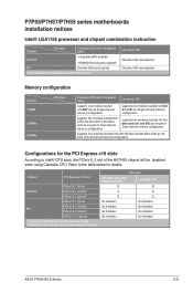
... integrated GPU) Lynnfield CPU O O X O O O No limitation No limitation No limitation No limitation No limitation No limitation No limitation No limitation ASUS P7H55-M LE Series 2-21 P7P55/P7H57/P7H55 series motherboards installation notices Intel® LGA1156 processor and chipset combination instruction Chipset CPU type Clarkdale CPU (with integrated GPU) H57/H55 • Integrated GPU enabled...
... integrated GPU) Lynnfield CPU O O X O O O No limitation No limitation No limitation No limitation No limitation No limitation No limitation No limitation ASUS P7H55-M LE Series 2-21 P7P55/P7H57/P7H55 series motherboards installation notices Intel® LGA1156 processor and chipset combination instruction Chipset CPU type Clarkdale CPU (with integrated GPU) H57/H55 • Integrated GPU enabled...

User Manual
Page 49
.... 21, 2010 EC Declaration of the FCC Rules. Country: TAIWAN Authorized representative in Europe: ASUS COMPUTER GmbH Address, City: HARKORT STR. 21-23, 40880 RATINGEN Country: GERMANY declare the following apparatus: Product name : Motherboard Model name : P7H55-M LE/SI;P7H55-M LX;P7H55-M LX2 conform with the essential requirements of the following directives: 2004/108/EC-EMC...
.... 21, 2010 EC Declaration of the FCC Rules. Country: TAIWAN Authorized representative in Europe: ASUS COMPUTER GmbH Address, City: HARKORT STR. 21-23, 40880 RATINGEN Country: GERMANY declare the following apparatus: Product name : Motherboard Model name : P7H55-M LE/SI;P7H55-M LX;P7H55-M LX2 conform with the essential requirements of the following directives: 2004/108/EC-EMC...


