User Manual
Page 2
... source code of this product is dependent on the preferred carrier and the location where you want to have it shipped to, by sending a request to anyone in it from http://support.asus.com/download; ii E5956 First Edition V1 July 2010 Copyright © 2010 ASUSTeK Computer Inc. No part of this manual, including the products and software...
... source code of this product is dependent on the preferred carrier and the location where you want to have it shipped to, by sending a request to anyone in it from http://support.asus.com/download; ii E5956 First Edition V1 July 2010 Copyright © 2010 ASUSTeK Computer Inc. No part of this manual, including the products and software...

User Manual
Page 3
... Unit (CPU 1-3 1.4 System memory 1-3 1.4.1 Overview 1-3 1.4.2 Memory configurations 1-4 1.5 Expansion slots 1-7 1.5.1 Installing an expansion card 1-7 1.5.2 Configuring an expansion card 1-7 1.5.3 PCI slots 1-7 1.5.4 PCI Express x4 slot 1-7 1.5.5 PCI Express x16 slot 1-7 1.6 Jumpers 1-8 1.7 Connectors 1-9 1.7.1 Rear panel ports 1-9 1.7.2 Internal connectors 1-10 1.8 Software support 1-17 1.8.1 Installing an operating system 1-17 1.8.2 Support DVD information 1-17 Chapter 2: BIOS information 2.1 Managing and updating your BIOS 2-1 2.1.1 ASUS Update 2-1 2.1.2 ASUS EZ Flash...
... Unit (CPU 1-3 1.4 System memory 1-3 1.4.1 Overview 1-3 1.4.2 Memory configurations 1-4 1.5 Expansion slots 1-7 1.5.1 Installing an expansion card 1-7 1.5.2 Configuring an expansion card 1-7 1.5.3 PCI slots 1-7 1.5.4 PCI Express x4 slot 1-7 1.5.5 PCI Express x16 slot 1-7 1.6 Jumpers 1-8 1.7 Connectors 1-9 1.7.1 Rear panel ports 1-9 1.7.2 Internal connectors 1-10 1.8 Software support 1-17 1.8.1 Installing an operating system 1-17 1.8.2 Support DVD information 1-17 Chapter 2: BIOS information 2.1 Managing and updating your BIOS 2-1 2.1.1 ASUS Update 2-1 2.1.2 ASUS EZ Flash...
User Manual
Page 8
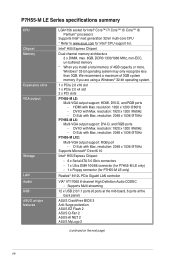
... with Max. D-Sub with Max. Supports Multi-streaming 12 x USB 2.0/1.1 ports (6 ports at the mid-board, 6 ports at the back panel) ASUS CrashFree BIOS 3 Anti-Surge protection ASUS EZ Flash 2 ASUS Q-Fan 2 ASUS AI NET 2 ASUS MyLogo 2 (continued on the next page) viii P7H55-M LE Series specifications summary CPU Chipset Memory Expansion slots VGA output Storage LAN Audio USB ASUS unique features LGA1156 socket for Intel® Core™ i7/ Core™ i5/ Core™ i3/ Pentium® processors Supports Intel® next generation 32nm multi-core CPU...
... with Max. D-Sub with Max. Supports Multi-streaming 12 x USB 2.0/1.1 ports (6 ports at the mid-board, 6 ports at the back panel) ASUS CrashFree BIOS 3 Anti-Surge protection ASUS EZ Flash 2 ASUS Q-Fan 2 ASUS AI NET 2 ASUS MyLogo 2 (continued on the next page) viii P7H55-M LE Series specifications summary CPU Chipset Memory Expansion slots VGA output Storage LAN Audio USB ASUS unique features LGA1156 socket for Intel® Core™ i7/ Core™ i5/ Core™ i3/ Pentium® processors Supports Intel® next generation 32nm multi-core CPU...
User Manual
Page 9
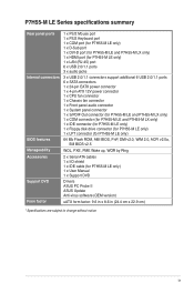
... P7H55-M LE Series specifications summary Rear panel ports Internal connectors BIOS features Manageability Accessories Support DVD Form factor 1 x PS/2 Mouse port 1 x PS/2 Keyboard port 1 x COM port (for P7H55-M LE only) 1 x D-Sub port 1 x DVI-D port (for P7H55-M LE and P7H55-M LX only) 1 x HDMI port (for P7H55-M LE only) 1 x LAN (RJ-45) port 6 x USB 2.0/1.1 ports 3 x audio jacks 3 x USB 2.0/1.1 connectors support additional 6 USB 2.0/1.1 ports 6 x SATA connectors 1 x 24-pin EATX power connector 1 x 4-pin ATX 12V power connector 1 x CPU fan connector 1 x Chassis fan connector 1 x Front panel...
... P7H55-M LE Series specifications summary Rear panel ports Internal connectors BIOS features Manageability Accessories Support DVD Form factor 1 x PS/2 Mouse port 1 x PS/2 Keyboard port 1 x COM port (for P7H55-M LE only) 1 x D-Sub port 1 x DVI-D port (for P7H55-M LE and P7H55-M LX only) 1 x HDMI port (for P7H55-M LE only) 1 x LAN (RJ-45) port 6 x USB 2.0/1.1 ports 3 x audio jacks 3 x USB 2.0/1.1 connectors support additional 6 USB 2.0/1.1 ports 6 x SATA connectors 1 x 24-pin EATX power connector 1 x 4-pin ATX 12V power connector 1 x CPU fan connector 1 x Chassis fan connector 1 x Front panel...

User Manual
Page 11
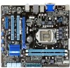
...IDE connector (40-1 pin PRI_EIDE) Page Connectors/Jumpers/Slots/LED 1-12 9. Onboard LED (SB_PWR) 11. Clear RTC RAM (3-pin CLRTC) 1-15 13. Front panel audio connector (10-1 pin AAFP) 1-16 Page 1-11 1-1 1-12 1-8 1-10 1-11 1-14 ASUS P7H55-M LE Series 1-2 ATX power connectors (24-pin EATXPWR, 4-pin ATX12V) 3. Serial port connectors (10-1 pin COM2) 6. 1.2 1.2.1 Motherboard overview Motherboard layout The layout varies with external ports goes to the chassis. Ensure that you install the motherboard into the holes indicated by circles to secure the motherboard to the rear part...
...IDE connector (40-1 pin PRI_EIDE) Page Connectors/Jumpers/Slots/LED 1-12 9. Onboard LED (SB_PWR) 11. Clear RTC RAM (3-pin CLRTC) 1-15 13. Front panel audio connector (10-1 pin AAFP) 1-16 Page 1-11 1-1 1-12 1-8 1-10 1-11 1-14 ASUS P7H55-M LE Series 1-2 ATX power connectors (24-pin EATXPWR, 4-pin ATX12V) 3. Serial port connectors (10-1 pin COM2) 6. 1.2 1.2.1 Motherboard overview Motherboard layout The layout varies with external ports goes to the chassis. Ensure that you install the motherboard into the holes indicated by circles to secure the motherboard to the rear part...
User Manual
Page 16
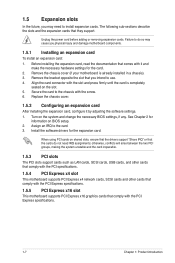
... the system and change the necessary BIOS settings, if any. Replace the chassis cover. 1.5.2 Configuring an expansion card After installing the expansion card, configure it and make the necessary hardware settings for the expansion card. Turn on BIOS setup. 2. Install the software drivers for the card. 2. When using PCI cards on the slot. 5. Before installing the expansion card, read the documentation that you physical injury and damage motherboard components. 1.5.1 Installing an expansion card To install an expansion card: 1. The following...
... the system and change the necessary BIOS settings, if any. Replace the chassis cover. 1.5.2 Configuring an expansion card After installing the expansion card, configure it and make the necessary hardware settings for the expansion card. Turn on BIOS setup. 2. Install the software drivers for the card. 2. When using PCI cards on the slot. 5. Before installing the expansion card, read the documentation that you physical injury and damage motherboard components. 1.5.1 Installing an expansion card To install an expansion card: 1. The following...
User Manual
Page 19
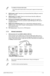
... 8-channel audio output: Use a chassis with DVI-I. 11. This port is for P7H55-M LE and P7H55-M LX only). Doing so will damage the motherboard! This port is for any of these connectors, then install the module to any DVI-D compatible device. Connect the USB module cable to a slot opening at the back of HD DVD, Blu-Ray, and other protected content. 12. DVI-D port (for a PS/2 keyboard. 1.7.2 Internal connectors 1. These USB connectors comply with the USB 2.0 specification...
... 8-channel audio output: Use a chassis with DVI-I. 11. This port is for P7H55-M LE and P7H55-M LX only). Doing so will damage the motherboard! This port is for any of these connectors, then install the module to any DVI-D compatible device. Connect the USB module cable to a slot opening at the back of HD DVD, Blu-Ray, and other protected content. 12. DVI-D port (for a PS/2 keyboard. 1.7.2 Internal connectors 1. These USB connectors comply with the USB 2.0 specification...

User Manual
Page 21
...; Reset button (2-pin RESET) This 2-pin connector is for the chassis-mounted reset button for the system power LED. ASUS P7H55-M LE Series 1-12 System panel connector (10-1 pin F_PANEL) This connector supports several chassis-mounted functions. DO NOT place jumper caps on the motherboard, making sure that the black wire of each cable matches the ground pin of the connector. The IDE LED lights up when you turn on the system power, and blinks when the system is in sleep mode. • Hard disk drive...
...; Reset button (2-pin RESET) This 2-pin connector is for the chassis-mounted reset button for the system power LED. ASUS P7H55-M LE Series 1-12 System panel connector (10-1 pin F_PANEL) This connector supports several chassis-mounted functions. DO NOT place jumper caps on the motherboard, making sure that the black wire of each cable matches the ground pin of the connector. The IDE LED lights up when you turn on the system power, and blinks when the system is in sleep mode. • Hard disk drive...
User Manual
Page 27
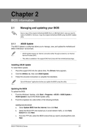
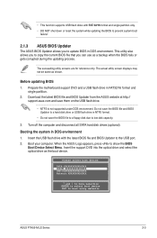
..., and update the motherboard BIOS in Windows® environment. • ASUS Update requires an Internet connection either of the original motherboard BIOS file to a USB flash disk in case you to complete the installation. Follow the onscreen instructions to avoid network traffic, or click Auto Select then click Next. From the Windows® desktop, click Start > Programs > ASUS > ASUS Update > ASUS Update to download then click Next. From the dropdown list, select either through a network or an Internet Service Provider...
..., and update the motherboard BIOS in Windows® environment. • ASUS Update requires an Internet connection either of the original motherboard BIOS file to a USB flash disk in case you to complete the installation. Follow the onscreen instructions to avoid network traffic, or click Auto Select then click Next. From the Windows® desktop, click Start > Programs > ASUS > ASUS Update > ASUS Update to download then click Next. From the dropdown list, select either through a network or an Internet Service Provider...
User Manual
Page 28
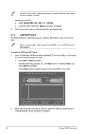
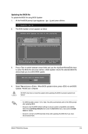
... Tools menu to select EZ Flash 2 and press to update the BIOS without using EZ Flash 2: 1. b. Always update the utility to avail all its features. ASUSTek EZ Flash 2 BIOS ROM Utility V4.14 Current ROM BOARD: P7H55-M LX VER: 0301 (H:00 B:00) DATE: 07/12/2010 Update ROM BOARD: Unknown VER: Unknown DATE: Unknown PATH: A:\ A: Note [Enter] Select or Load [Up/Down/Home/End] Move [Tab] Switch [B] Backup [V] Drive Info [ESC] Exit 2. Locate the BIOS file...
... Tools menu to select EZ Flash 2 and press to update the BIOS without using EZ Flash 2: 1. b. Always update the utility to avail all its features. ASUSTek EZ Flash 2 BIOS ROM Utility V4.14 Current ROM BOARD: P7H55-M LX VER: 0301 (H:00 B:00) DATE: 07/12/2010 Update ROM BOARD: Unknown VER: Unknown DATE: Unknown PATH: A:\ A: Note [Enter] Select or Load [Up/Down/Home/End] Move [Tab] Switch [B] Backup [V] Drive Info [ESC] Exit 2. Locate the BIOS file...
User Manual
Page 29
The actual utility screen displays may not be same as the boot device. Do not save the BIOS file and BIOS Updater to a hard disk drive or USB flash drive in DOS environment. Turn off the computer and disconnect all SATA hard disk drives (optional). Insert the support DVD into the optical drive and select the optical drive as shown. Before updating BIOS 1. Prepare the motherboard support DVD and a USB flash drive in DOS environment 1. Please select boot device: SATA:XXXXXXXXXXXXXXXX CDROM:XXXXXXXXXXXXXXX USB:XXXXXXXXXXXXXXXXX Network:XXXXXXXXXXXXX ↑ and...
The actual utility screen displays may not be same as the boot device. Do not save the BIOS file and BIOS Updater to a hard disk drive or USB flash drive in DOS environment. Turn off the computer and disconnect all SATA hard disk drives (optional). Insert the support DVD into the optical drive and select the optical drive as shown. Before updating BIOS 1. Prepare the motherboard support DVD and a USB flash drive in DOS environment 1. Please select boot device: SATA:XXXXXXXXXXXXXXXX CDROM:XXXXXXXXXXXXXXX USB:XXXXXXXXXXXXXXXXX Network:XXXXXXXXXXXXX ↑ and...
User Manual
Page 31
... keys to exit BIOS Updater. At the FreeDOS prompt, type bupdater /pc /g and press . ASUSTek BIOS Updater for details. • Ensure to connect all SATA hard disk drives after updating BIOS. • Ensure to load the BIOS default settings to update BIOS? Are you sure to ensure system compatibility and stability. The BIOS Updater screen appears as below. Restart your computer. Select the Load Setup Defaults item under the Exit BIOS menu. ASUS P7H55-M LE Series 2-5 Yes No 4. Updating the BIOS file To update the BIOS file using BIOS Updater...
... keys to exit BIOS Updater. At the FreeDOS prompt, type bupdater /pc /g and press . ASUSTek BIOS Updater for details. • Ensure to connect all SATA hard disk drives after updating BIOS. • Ensure to load the BIOS default settings to update BIOS? Are you sure to ensure system compatibility and stability. The BIOS Updater screen appears as below. Restart your computer. Select the Load Setup Defaults item under the Exit BIOS menu. ASUS P7H55-M LE Series 2-5 Yes No 4. Updating the BIOS file To update the BIOS file using BIOS Updater...
User Manual
Page 32
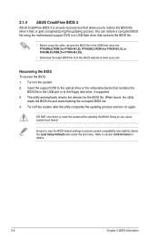
... during the updating process. You can cause system boot failure! Refer to section 2.8 Exit menu for the BIOS file. Doing so can restore a corrupted BIOS file using the motherboard support DVD or a USB flash drive that contains the BIOS file. • Before using this utility, rename the BIOS file in the USB flash drive into P7H55MLE.ROM (for P7H55-M LE), P7H55MLX.ROM (for P7H55-M LX), or PH55MLX2.ROM (for P7H55-M LX2). • Download the latest BIOS file from the ASUS website at www.asus.com. Recovering...
... during the updating process. You can cause system boot failure! Refer to section 2.8 Exit menu for the BIOS file. Doing so can restore a corrupted BIOS file using the motherboard support DVD or a USB flash drive that contains the BIOS file. • Before using this utility, rename the BIOS file in the USB flash drive into P7H55MLE.ROM (for P7H55-M LE), P7H55MLX.ROM (for P7H55-M LX), or PH55MLX2.ROM (for P7H55-M LX2). • Download the latest BIOS file from the ASUS website at www.asus.com. Recovering...
User Manual
Page 35
... SATA device type. LBA/Large Mode [Auto] Enables or disables the LBA mode. Configuration options: [Disabled] [Auto] PIO Mode [Auto] Selects the PIO mode. Configuration options: [Auto] [Disabled] [Enabled] 32Bit Data Transfer [Enabled] Enables or disables 32-bit data transfer. Configuration options: [IDE] [AHCI] Due to Intel chipset driver support regulation, the AHCI mode is either a ZIP, LS-120, or MO drive. ASUS P7H55-M LE Series 2-9 When set or change the configurations for the Serial ATA connectors supported by Windows Vista/7 with LBA mode disabled. Configuration options...
... SATA device type. LBA/Large Mode [Auto] Enables or disables the LBA mode. Configuration options: [Disabled] [Auto] PIO Mode [Auto] Selects the PIO mode. Configuration options: [Auto] [Disabled] [Enabled] 32Bit Data Transfer [Enabled] Enables or disables 32-bit data transfer. Configuration options: [IDE] [AHCI] Due to Intel chipset driver support regulation, the AHCI mode is either a ZIP, LS-120, or MO drive. ASUS P7H55-M LE Series 2-9 When set or change the configurations for the Serial ATA connectors supported by Windows Vista/7 with LBA mode disabled. Configuration options...

User Manual
Page 36
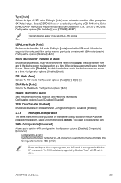
... and other system devices. System Memory Displays the auto-detected system memory. 2.4 Advanced menu The Advanced menu items allow you an overview of the Advanced menu items. Incorrect field values can cause the system to change the settings for detecting ATA/ATAPI devices. Main Advanced Power BIOS SETUP UTILITY Boot Tools Exit CPU Configuration Chipset Onboard Devices Configuration USB Configuration PCIPnP Intel VT-d Configuration Configure CPU. 2.4.1 CPU Configuration The items in ratio numbers directly. Key in this menu. Configuration options: [0] [5] [10] [15] [20...
... and other system devices. System Memory Displays the auto-detected system memory. 2.4 Advanced menu The Advanced menu items allow you an overview of the Advanced menu items. Incorrect field values can cause the system to change the settings for detecting ATA/ATAPI devices. Main Advanced Power BIOS SETUP UTILITY Boot Tools Exit CPU Configuration Chipset Onboard Devices Configuration USB Configuration PCIPnP Intel VT-d Configuration Configure CPU. 2.4.1 CPU Configuration The items in ratio numbers directly. Key in this menu. Configuration options: [0] [5] [10] [15] [20...

User Manual
Page 38
...], the CPU speed is [PEG/PCI]. Uncore configuration DRAM Frequency [Auto] Allows you to select the front panel type. Configuration options: [Enabled] [Disabled] Front Panel Type [HD Audio] Allows you to use as the primary boot device. Configuration options: [Enabled] [Disabled] Intel(R) TurboMode Tech [Enabled] This item appears only if you to decide which graphics controller to adjust the DRAM frequency. Configuration options: [Disabled] [Enabled] Initiate Graphic Adapter [PCIE/PCI] Allows you set HD Audio mode. Configuration options: [AC97] [HD Audio] 2-12 Chapter 2: BIOS...
...], the CPU speed is [PEG/PCI]. Uncore configuration DRAM Frequency [Auto] Allows you to select the front panel type. Configuration options: [Enabled] [Disabled] Front Panel Type [HD Audio] Allows you to use as the primary boot device. Configuration options: [Enabled] [Disabled] Intel(R) TurboMode Tech [Enabled] This item appears only if you to decide which graphics controller to adjust the DRAM frequency. Configuration options: [Disabled] [Enabled] Initiate Graphic Adapter [PCIE/PCI] Allows you set HD Audio mode. Configuration options: [AC97] [HD Audio] 2-12 Chapter 2: BIOS...
User Manual
Page 39
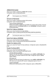
... to enable or disable the onboard LAN controller. This item allows you to select the EPP version. Configuration options: [IRQ5] [IRQ7] ASUS P7H55-M LE Series 2-13 Onboard LAN [Enabled] Allows you to enable or disable the boot ROM in the onboard LAN controller. Configuration options: [Normal] [EPP] [ECP] [EPP+ECP] ECP Mode DMA Channel [DMA3] Appears only when the Parallel Port Mode item is set to [ECP] or [EPP+ECP]. Configuration options: [1.9] [1.7] Parallel Port IRQ [IRQ7] Allows you to select the Serial...
... to enable or disable the onboard LAN controller. This item allows you to select the EPP version. Configuration options: [IRQ5] [IRQ7] ASUS P7H55-M LE Series 2-13 Onboard LAN [Enabled] Allows you to enable or disable the boot ROM in the onboard LAN controller. Configuration options: [Normal] [EPP] [ECP] [EPP+ECP] ECP Mode DMA Channel [DMA3] Appears only when the Parallel Port Mode item is set to [ECP] or [EPP+ECP]. Configuration options: [1.9] [1.7] Parallel Port IRQ [IRQ7] Allows you to select the Serial...

User Manual
Page 40
... Sec] [40 Sec] Emulation Type [Auto] Allows you to initialize. The menu includes setting IRQ and DMA channel resources for either PCI/PnP or legacy ISA devices, and setting the memory size block for Legacy USB storage devices, including USB flash drives and USB hard drives. Plug and Play O/S [No] When set the maximum time that the BIOS waits for the USB storage device to enable or disable support for legacy ISA devices. Configuration options: [Auto] [Floppy] [Forced 2.4.5 PCI PnP The PCI PnP menu items allow you to display the configuration options.
... Sec] [40 Sec] Emulation Type [Auto] Allows you to initialize. The menu includes setting IRQ and DMA channel resources for either PCI/PnP or legacy ISA devices, and setting the memory size block for Legacy USB storage devices, including USB flash drives and USB hard drives. Plug and Play O/S [No] When set the maximum time that the BIOS waits for the USB storage device to enable or disable support for legacy ISA devices. Configuration options: [Auto] [Floppy] [Forced 2.4.5 PCI PnP The PCI PnP menu items allow you to display the configuration options.
User Manual
Page 41
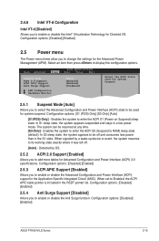
... Main Advanced Power BIOS SETUP UTILITY Boot Tools Exit Suspend Mode ACPI 2.0 Support ACPI APIC Support Anti Surge Support [Auto] [Enabled] [Enabled] [Disabled] APM Configuration Hardware Monitor Select the ACPI state used for the Advanced Power Management (APM). When signaled by OS. 2.5.2 ACPI 2.0 Support [Enabled] Allows you to enable or disable the Advanced Configuration and Power Interface (ACPI) support in the Application-Specific Integrated Circuit (ASIC). Configuration options: [S1 (POS) Only] [S3 Only] [Auto] [S1(POS) Only] - Enables the system to enter the ACPI...
... Main Advanced Power BIOS SETUP UTILITY Boot Tools Exit Suspend Mode ACPI 2.0 Support ACPI APIC Support Anti Surge Support [Auto] [Enabled] [Enabled] [Disabled] APM Configuration Hardware Monitor Select the ACPI state used for the Advanced Power Management (APM). When signaled by OS. 2.5.2 ACPI 2.0 Support [Enabled] Allows you to enable or disable the Advanced Configuration and Power Interface (ACPI) support in the Application-Specific Integrated Circuit (ASIC). Configuration options: [S1 (POS) Only] [S3 Only] [Auto] [S1(POS) Only] - Enables the system to enter the ACPI...

User Manual
Page 43
... you to enable or disable the CPU/Chassis Q-Fan function. Configuration options: [1st FLOPPY DRIVE] (for P7H55-M LE) / [Removable Dev.] (for P7H55-M LX) [Hard Drive] [ATAPI CD-ROM] [Disabled] • To select the boot device suring system startup, press when ASUS Logo appears. • To access Windows® OS in Safe Mode, do any of devices installed in the system. Configuration options: [Disabled] [Enabled] Set this item allows the BIOS to boot the system. ASUS P7H55-M LE Series 2-17 Main Advanced Power BIOS SETUP UTILITY Boot Tools Exit Boot Settings Boot Device...
... you to enable or disable the CPU/Chassis Q-Fan function. Configuration options: [1st FLOPPY DRIVE] (for P7H55-M LE) / [Removable Dev.] (for P7H55-M LX) [Hard Drive] [ATAPI CD-ROM] [Disabled] • To select the boot device suring system startup, press when ASUS Logo appears. • To access Windows® OS in Safe Mode, do any of devices installed in the system. Configuration options: [Disabled] [Enabled] Set this item allows the BIOS to boot the system. ASUS P7H55-M LE Series 2-17 Main Advanced Power BIOS SETUP UTILITY Boot Tools Exit Boot Settings Boot Device...


