User Manual
Page 11
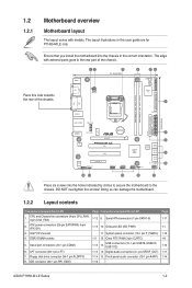
... 1-13 10. Front panel audio connector (10-1 pin AAFP) 1-16 Page 1-11 1-1 1-12 1-8 1-10 1-11 1-14 ASUS P7H55-M LE Series 1-2 The layout illustrations in the correct orientation. CPU and Chassis fan connectors (4-pin CPU_FAN, 3-pin CHA_FAN) 2. ATX power ..., USB1112) 1-15 14. KBMS 12 3 21.8cm(8.6in) 4 56 COM2 COM1 Place this user guide are for P7H55-M LE only. DDR3 DIMM sockets 5. 1.2 1.2.1 Motherboard overview Motherboard layout The layout varies with external ports goes to the chassis... contents Connectors/Jumpers/Slots/LED 1. Clear RTC RAM (3-pin CLRTC) 1-15 13.
... 1-13 10. Front panel audio connector (10-1 pin AAFP) 1-16 Page 1-11 1-1 1-12 1-8 1-10 1-11 1-14 ASUS P7H55-M LE Series 1-2 The layout illustrations in the correct orientation. CPU and Chassis fan connectors (4-pin CPU_FAN, 3-pin CHA_FAN) 2. ATX power ..., USB1112) 1-15 14. KBMS 12 3 21.8cm(8.6in) 4 56 COM2 COM1 Place this user guide are for P7H55-M LE only. DDR3 DIMM sockets 5. 1.2 1.2.1 Motherboard overview Motherboard layout The layout varies with external ports goes to the chassis... contents Connectors/Jumpers/Slots/LED 1. Clear RTC RAM (3-pin CLRTC) 1-15 13.
User Manual
Page 17
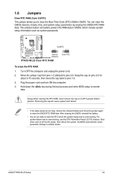
...failure! • If the steps above do not need to clear the RTC when the system hangs due to clear the CMOS RTC RAM data. After clearing the CMOS, reinstall the battery. • You do not help, remove the onboard battery and move the cap ..., and system setup parameters by erasing the CMOS RTC RAM data. ASUS P7H55-M LE Series 1-8 The onboard button cell battery powers the RAM data in CMOS. P7H55-M LE CLRTC 12 23 Normal (Default) Clear RTC P7H55-M LE Clear RTC RAM To erase the RTC RAM: 1. 1.6 Jumpers Clear RTC RAM (3-pin CLRTC) This jumper allows you to pins 2-3....
...failure! • If the steps above do not need to clear the RTC when the system hangs due to clear the CMOS RTC RAM data. After clearing the CMOS, reinstall the battery. • You do not help, remove the onboard battery and move the cap ..., and system setup parameters by erasing the CMOS RTC RAM data. ASUS P7H55-M LE Series 1-8 The onboard button cell battery powers the RAM data in CMOS. P7H55-M LE CLRTC 12 23 Normal (Default) Clear RTC P7H55-M LE Clear RTC RAM To erase the RTC RAM: 1. 1.6 Jumpers Clear RTC RAM (3-pin CLRTC) This jumper allows you to pins 2-3....
User Manual
Page 41
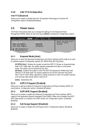
... Intel® Virtualization Technology for Directed I/O. In S1 sleep state, the system appears suspended and stays in the RSDT pointer list. Configuration options: [Disabled] [Enabled] ASUS P7H55-M LE Series 2-15 Configuration options: [S1 (POS) Only] [S3 Only] [Auto] [S1(POS) Only] - Configuration options: [Disabled] [Enabled] 2.5.4 Anti Surge Support [Disabled] Allows you to ... Allows you to change the settings for the Advanced Power Management (APM). Configuration options: [Disabled] [Enabled] 2.5 Power menu The Power menu items allow you to RAM) sleep state (default).
... Intel® Virtualization Technology for Directed I/O. In S1 sleep state, the system appears suspended and stays in the RSDT pointer list. Configuration options: [Disabled] [Enabled] ASUS P7H55-M LE Series 2-15 Configuration options: [S1 (POS) Only] [S3 Only] [Auto] [S1(POS) Only] - Configuration options: [Disabled] [Enabled] 2.5.4 Anti Surge Support [Disabled] Allows you to ... Allows you to change the settings for the Advanced Power Management (APM). Configuration options: [Disabled] [Enabled] 2.5 Power menu The Power menu items allow you to RAM) sleep state (default).
User Manual
Page 44
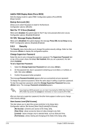
...BIOS information Confirm the password when prompted. allows access but does not allow you can clear it by erasing the CMOS Real Time Clock (RTC) RAM. Configuration options: [Disabled] [Enabled] Hit 'DEL' Message Display [Enabled] When set or change the supervisor password. The Supervisor Password item ...Select an item then press to be pressed when error occurs. See section 1.6 Jumpers for option ROM. prevents user access to erase the RTC RAM. allows viewing and changing all the fields in a password containing up to run Setup during POST. Configuration options: [Force BIOS] [Keep ...
...BIOS information Confirm the password when prompted. allows access but does not allow you can clear it by erasing the CMOS Real Time Clock (RTC) RAM. Configuration options: [Disabled] [Enabled] Hit 'DEL' Message Display [Enabled] When set or change the supervisor password. The Supervisor Password item ...Select an item then press to be pressed when error occurs. See section 1.6 Jumpers for option ROM. prevents user access to erase the RTC RAM. allows viewing and changing all the fields in a password containing up to run Setup during POST. Configuration options: [Force BIOS] [Keep ...

User Manual
Page 46
... the PC is turned off. Discard Changes This option allows you to exit. Pressing does not immediately exit this operation. Select OK to the CMOS RAM. F10 key can be used for this menu. Exit & Save Changes Once you are saved to load default values. When you select this option,...the changes that you made and restore the previously saved values. Select OK to save changes and exit. An onboard backup battery sustains the CMOS RAM so it stays on the Setup menus. Select OK to discard any changes and load the previously saved values. After selecting this option, a ...
... the PC is turned off. Discard Changes This option allows you to exit. Pressing does not immediately exit this operation. Select OK to the CMOS RAM. F10 key can be used for this menu. Exit & Save Changes Once you are saved to load default values. When you select this option,...the changes that you made and restore the previously saved values. Select OK to save changes and exit. An onboard backup battery sustains the CMOS RAM so it stays on the Setup menus. Select OK to discard any changes and load the previously saved values. After selecting this option, a ...


