User Manual
Page 2
...problems in the GPL) for the GPL Software, and/or the complete corresponding source code of the LGPL Software (with you want to have it from http://support.asus.com/download; ASUS ASSUMES NO RESPONSIBILITY OR LIABILITY FOR ANY ERRORS OR INACCURACIES THAT MAY APPEAR IN THIS MANUAL, INCLUDING THE PRODUCTS AND SOFTWARE...complete source code as the corresponding binary/object code. SPECIFICATIONS AND INFORMATION CONTAINED IN THIS MANUAL ARE FURNISHED FOR INFORMATIONAL USE ONLY, AND ARE SUBJECT TO CHANGE AT ANY TIME WITHOUT NOTICE, AND SHOULD NOT BE CONSTRUED AS A COMMITMENT BY ASUS. E5956 First...
...problems in the GPL) for the GPL Software, and/or the complete corresponding source code of the LGPL Software (with you want to have it from http://support.asus.com/download; ASUS ASSUMES NO RESPONSIBILITY OR LIABILITY FOR ANY ERRORS OR INACCURACIES THAT MAY APPEAR IN THIS MANUAL, INCLUDING THE PRODUCTS AND SOFTWARE...complete source code as the corresponding binary/object code. SPECIFICATIONS AND INFORMATION CONTAINED IN THIS MANUAL ARE FURNISHED FOR INFORMATIONAL USE ONLY, AND ARE SUBJECT TO CHANGE AT ANY TIME WITHOUT NOTICE, AND SHOULD NOT BE CONSTRUED AS A COMMITMENT BY ASUS. E5956 First...
User Manual
Page 3
... Unit (CPU 1-3 1.4 System memory 1-3 1.4.1 Overview 1-3 1.4.2 Memory configurations 1-4 1.5 Expansion slots 1-7 1.5.1 Installing an expansion card 1-7 1.5.2 Configuring an expansion card 1-7 1.5.3 PCI slots 1-7 1.5.4 PCI Express x4 slot 1-7 1.5.5 PCI Express x16 slot 1-7 1.6 Jumpers 1-8 1.7 Connectors 1-9 1.7.1 Rear panel ports 1-9 1.7.2 Internal connectors 1-10 1.8 Software support 1-17 1.8.1 Installing an operating system 1-17 1.8.2 Support DVD information 1-17 Chapter 2: BIOS information 2.1 Managing and updating your BIOS 2-1 2.1.1 ASUS Update 2-1 2.1.2 ASUS EZ Flash...
... Unit (CPU 1-3 1.4 System memory 1-3 1.4.1 Overview 1-3 1.4.2 Memory configurations 1-4 1.5 Expansion slots 1-7 1.5.1 Installing an expansion card 1-7 1.5.2 Configuring an expansion card 1-7 1.5.3 PCI slots 1-7 1.5.4 PCI Express x4 slot 1-7 1.5.5 PCI Express x16 slot 1-7 1.6 Jumpers 1-8 1.7 Connectors 1-9 1.7.1 Rear panel ports 1-9 1.7.2 Internal connectors 1-10 1.8 Software support 1-17 1.8.1 Installing an operating system 1-17 1.8.2 Support DVD information 1-17 Chapter 2: BIOS information 2.1 Managing and updating your BIOS 2-1 2.1.1 ASUS Update 2-1 2.1.2 ASUS EZ Flash...
User Manual
Page 9
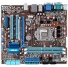
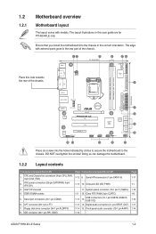
... P7H55-M LE Series specifications summary Rear panel ports Internal connectors BIOS features Manageability Accessories Support DVD Form factor 1 x PS/2 Mouse port 1 x PS/2 Keyboard port 1 x COM port (for P7H55-M LE only) 1 x D-Sub port 1 x DVI-D port (for P7H55-M LE and P7H55-M LX only) 1 x HDMI port (for P7H55-M LE only) 1 x LAN (RJ-45) port 6 x USB 2.0/1.1 ports 3 x audio jacks 3 x USB 2.0/1.1 connectors support additional 6 USB 2.0/1.1 ports 6 x SATA connectors 1 x 24-pin EATX power connector 1 x 4-pin ATX 12V power connector 1 x CPU fan connector 1 x Chassis fan connector 1 x Front panel...
... P7H55-M LE Series specifications summary Rear panel ports Internal connectors BIOS features Manageability Accessories Support DVD Form factor 1 x PS/2 Mouse port 1 x PS/2 Keyboard port 1 x COM port (for P7H55-M LE only) 1 x D-Sub port 1 x DVI-D port (for P7H55-M LE and P7H55-M LX only) 1 x HDMI port (for P7H55-M LE only) 1 x LAN (RJ-45) port 6 x USB 2.0/1.1 ports 3 x audio jacks 3 x USB 2.0/1.1 connectors support additional 6 USB 2.0/1.1 ports 6 x SATA connectors 1 x 24-pin EATX power connector 1 x 4-pin ATX 12V power connector 1 x CPU fan connector 1 x Chassis fan connector 1 x Front panel...
User Manual
Page 11
... motherboard into the holes indicated by circles to secure the motherboard to the rear part of the chassis. ATX power connectors (24-pin EATXPWR, 4-pin ATX12V) 3. IDE connector (40-1 pin PRI_EIDE) Page Connectors/Jumpers/Slots/LED 1-12 9. The edge with models. USB connectors (10-1 pin USB78, USB910, USB1112) 1-15 14. Doing so can damage the motherboard. 1.2.2 Layout contents Connectors/Jumpers/Slots/LED 1. System panel connector (10-1 pin F_PANEL) 1-3 12. Front panel audio connector (10-1 pin AAFP) 1-16 Page 1-11 1-1 1-12 1-8 1-10 1-11 1-14 ASUS P7H55-M LE Series...
... motherboard into the holes indicated by circles to secure the motherboard to the rear part of the chassis. ATX power connectors (24-pin EATXPWR, 4-pin ATX12V) 3. IDE connector (40-1 pin PRI_EIDE) Page Connectors/Jumpers/Slots/LED 1-12 9. The edge with models. USB connectors (10-1 pin USB78, USB910, USB1112) 1-15 14. Doing so can damage the motherboard. 1.2.2 Layout contents Connectors/Jumpers/Slots/LED 1. System panel connector (10-1 pin F_PANEL) 1-3 12. Front panel audio connector (10-1 pin AAFP) 1-16 Page 1-11 1-1 1-12 1-8 1-10 1-11 1-14 ASUS P7H55-M LE Series...
User Manual
Page 16
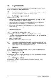
...slots support cards such as LAN cards, SCSI cards, USB cards, and other cards that comply with the PCI specifications. 1.5.4 PCI Express x4 slot This motherboard supports PCI Express x4 network cards, SCSI cards and other cards that comply with the PCI Express specifications. 1.5.5 PCI Express x16 slot This motherboard supports PCI Express x16 graphics cards that you physical injury and damage motherboard components. 1.5.1 Installing an expansion card To install an expansion card: 1. Turn on BIOS setup. 2. See Chapter 2 for information on the system and change the necessary BIOS settings...
...slots support cards such as LAN cards, SCSI cards, USB cards, and other cards that comply with the PCI specifications. 1.5.4 PCI Express x4 slot This motherboard supports PCI Express x4 network cards, SCSI cards and other cards that comply with the PCI Express specifications. 1.5.5 PCI Express x16 slot This motherboard supports PCI Express x16 graphics cards that you physical injury and damage motherboard components. 1.5.1 Installing an expansion card To install an expansion card: 1. Turn on BIOS setup. 2. See Chapter 2 for information on the system and change the necessary BIOS settings...
User Manual
Page 19
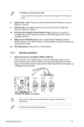
...motherboard! This is a High-Definition Mulltimedia Interface (HDMI) connector, and is for USB 2.0 ports. USB connectors (10-1 pin USB78, USB910, USB1112) These connectors are for a PS/2 keyboard. 1.7.2 Internal connectors 1. These USB connectors comply with the USB 2.0 specification that supports up to support an 8-channel audio output. 8. To configure an 8-channel audio output: Use a chassis with HD audio module in the front panel to 480Mbps connection speed. This port is HDCP compliant allowing playback of these connectors, then install the module to any DVI-D compatible...
...motherboard! This is a High-Definition Mulltimedia Interface (HDMI) connector, and is for USB 2.0 ports. USB connectors (10-1 pin USB78, USB910, USB1112) These connectors are for a PS/2 keyboard. 1.7.2 Internal connectors 1. These USB connectors comply with the USB 2.0 specification that supports up to support an 8-channel audio output. 8. To configure an 8-channel audio output: Use a chassis with HD audio module in the front panel to 480Mbps connection speed. This port is HDCP compliant allowing playback of these connectors, then install the module to any DVI-D compatible...
User Manual
Page 21
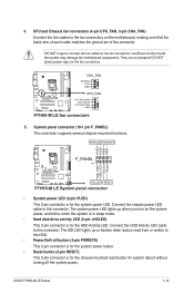
... in sleep mode. • Hard disk drive activity LED (2-pin +HDLED) This 2-pin connector is for the HDD Activity LED. CHA_FAN Rotation +12V GND P7H55-M LE CPU_FAN CPU FAN PWM CPU FAN IN CPU FAN PWR GND P7H55-M LE fan connectors 5. Connect the chassis power LED cable to this connector. DO NOT forget to connect the fan cables to the fan connectors on the motherboard, making sure that the black wire of each cable matches the ground pin of the connector. Ground Reset F_PANEL PIN 1 P7H55-M LE HD_LED RESET P7H55-M LE System panel connector • System power LED (2-pin PLED) This 2-pin...
... in sleep mode. • Hard disk drive activity LED (2-pin +HDLED) This 2-pin connector is for the HDD Activity LED. CHA_FAN Rotation +12V GND P7H55-M LE CPU_FAN CPU FAN PWM CPU FAN IN CPU FAN PWR GND P7H55-M LE fan connectors 5. Connect the chassis power LED cable to this connector. DO NOT forget to connect the fan cables to the fan connectors on the motherboard, making sure that the black wire of each cable matches the ground pin of the connector. Ground Reset F_PANEL PIN 1 P7H55-M LE HD_LED RESET P7H55-M LE System panel connector • System power LED (2-pin PLED) This 2-pin...

User Manual
Page 27
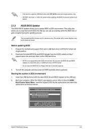
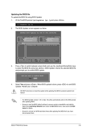
...and updating your BIOS Save a copy of the following methods: Updating from the Internet, then click Next. Click the Utilities tab, then click ASUS Update. 3. Follow the onscreen instructions to launch the ASUS Update utility. 2. From the Windows® desktop, click Start > Programs > ASUS > ASUS Update > ASUS Update to complete the installation. The Drivers menu appears. 2. Place the support DVD into the optical drive. ASUS P7H55-M LE Series 2-1 Installing ASUS Update To install ASUS Update: 1. From the dropdown list, select either through a network or an Internet Service...
...and updating your BIOS Save a copy of the following methods: Updating from the Internet, then click Next. Click the Utilities tab, then click ASUS Update. 3. Follow the onscreen instructions to launch the ASUS Update utility. 2. From the Windows® desktop, click Start > Programs > ASUS > ASUS Update > ASUS Update to complete the installation. The Drivers menu appears. 2. Place the support DVD into the optical drive. ASUS P7H55-M LE Series 2-1 Installing ASUS Update To install ASUS Update: 1. From the dropdown list, select either through a network or an Internet Service...
User Manual
Page 28
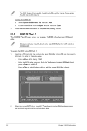
... + during POST. • Enter the BIOS setup program. b. Locate the BIOS file from a BIOS file a. Insert the USB flash disk that contains the latest BIOS file to switch between drives until the correct BIOS file is found , EZ Flash 2 performs the BIOS update process and automatically reboots the system when done. 2-2 Chapter 2: BIOS information To update the BIOS using this utility, download the latest BIOS file from a file, then click Next. The ASUS Update utility is found . ASUSTek EZ Flash 2 BIOS ROM Utility V4.14 Current ROM BOARD: P7H55-M LX...
... + during POST. • Enter the BIOS setup program. b. Locate the BIOS file from a BIOS file a. Insert the USB flash disk that contains the latest BIOS file to switch between drives until the correct BIOS file is found , EZ Flash 2 performs the BIOS update process and automatically reboots the system when done. 2-2 Chapter 2: BIOS information To update the BIOS using this utility, download the latest BIOS file from a file, then click Next. The ASUS Update utility is found . ASUSTek EZ Flash 2 BIOS ROM Utility V4.14 Current ROM BOARD: P7H55-M LX...
User Manual
Page 29
... to boot using defaults ASUS P7H55-M LE Series 2-3 Insert the support DVD into the optical drive and select the optical drive as shown. Please select boot device: SATA:XXXXXXXXXXXXXXXX CDROM:XXXXXXXXXXXXXXX USB:XXXXXXXXXXXXXXXXX Network:XXXXXXXXXXXXX ↑ and ↓ to move selection ENTER to select boot device ESC to show the BIOS Boot Device Select Menu. Do not save the BIOS file and BIOS Updater to a hard disk drive or USB flash drive in DOS environment. The actual utility screen displays may not be same as the boot device...
... to boot using defaults ASUS P7H55-M LE Series 2-3 Insert the support DVD into the optical drive and select the optical drive as shown. Please select boot device: SATA:XXXXXXXXXXXXXXXX CDROM:XXXXXXXXXXXXXXX USB:XXXXXXXXXXXXXXXXX Network:XXXXXXXXXXXXX ↑ and ↓ to move selection ENTER to select boot device ESC to show the BIOS Boot Device Select Menu. Do not save the BIOS file and BIOS Updater to a hard disk drive or USB flash drive in DOS environment. The actual utility screen displays may not be same as the boot device...
User Manual
Page 31
Yes No 4. Updating the BIOS file To update the BIOS file using BIOS Updater 1. ASUS P7H55-M LE Series 2-5 At the FreeDOS prompt, type bupdater /pc /g and press . See section 2.8 Exit menu for DOS V1.00b [09/06/22] Current ROM BOARD: P7H55-M LX VER: 0301 DATE: 07/12/2010 Update ROM BOARD: Unknown VER: Unknown DATE: Unknown PATH: A:\ A: P7H55MLX.ROM 2097152 2010-07-12 17:30:48 Note [Enter] Select or Load [Tab] Switch [Up/Down...
Yes No 4. Updating the BIOS file To update the BIOS file using BIOS Updater 1. ASUS P7H55-M LE Series 2-5 At the FreeDOS prompt, type bupdater /pc /g and press . See section 2.8 Exit menu for DOS V1.00b [09/06/22] Current ROM BOARD: P7H55-M LX VER: 0301 DATE: 07/12/2010 Update ROM BOARD: Unknown VER: Unknown DATE: Unknown PATH: A:\ A: P7H55MLX.ROM 2097152 2010-07-12 17:30:48 Note [Enter] Select or Load [Tab] Switch [Up/Down...
User Manual
Page 32
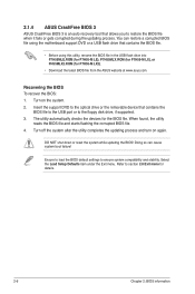
... reset the system while updating the BIOS! Doing so can restore a corrupted BIOS file using the motherboard support DVD or a USB flash drive that contains the BIOS file. • Before using this utility, rename the BIOS file in the USB flash drive into P7H55MLE.ROM (for P7H55-M LE), P7H55MLX.ROM (for P7H55-M LX), or PH55MLX2.ROM (for P7H55-M LX2). • Download the latest BIOS file from the ASUS website at www.asus.com. Select the Load Setup Defaults item under the Exit menu. You can cause system boot failure! Turn...
... reset the system while updating the BIOS! Doing so can restore a corrupted BIOS file using the motherboard support DVD or a USB flash drive that contains the BIOS file. • Before using this utility, rename the BIOS file in the USB flash drive into P7H55MLE.ROM (for P7H55-M LE), P7H55MLX.ROM (for P7H55-M LX), or PH55MLX2.ROM (for P7H55-M LX2). • Download the latest BIOS file from the ASUS website at www.asus.com. Select the Load Setup Defaults item under the Exit menu. You can cause system boot failure! Turn...
User Manual
Page 35
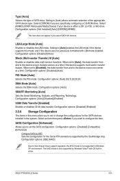
... you are specifically configuring a CD-ROM drive. SATA Configuration [Enhanced] Allows you select SATA 5/6 devices. Type [Auto] Selects the type of the appropriate SATA device type. The AHCI mode is only supported by the Southbridge chip. When set or change the configurations for the Serial ATA connectors supported by Windows Vista/7 with LBA mode disabled. Configuration options: [Auto] SMART Monitoring [Auto] Sets the Smart Monitoring, Analysis, and Reporting Technology. Configuration options: [Disabled] [Auto] Block (Multi-sector Transfer) M [Auto] Enables or disables data multi...
... you are specifically configuring a CD-ROM drive. SATA Configuration [Enhanced] Allows you select SATA 5/6 devices. Type [Auto] Selects the type of the appropriate SATA device type. The AHCI mode is only supported by the Southbridge chip. When set or change the configurations for the Serial ATA connectors supported by Windows Vista/7 with LBA mode disabled. Configuration options: [Auto] SMART Monitoring [Auto] Sets the Smart Monitoring, Analysis, and Reporting Technology. Configuration options: [Disabled] [Auto] Block (Multi-sector Transfer) M [Auto] Enables or disables data multi...
User Manual
Page 36
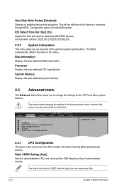
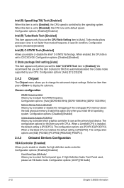
... to change the settings for detecting ATA/ATAPI devices. Key in CMOS, then the actual and set values may differ. 2-10 Chapter 2: BIOS information Configuration option: [Disabled] [Enabled] IDE Detect Time Out (Sec) [35] Selects the time out value for the CPU and other system devices. Bios Information Displays the auto-detected BIOS information. Main Advanced Power BIOS SETUP UTILITY Boot Tools Exit CPU Configuration Chipset Onboard Devices Configuration USB Configuration PCIPnP Intel VT-d Configuration Configure CPU. 2.4.1 CPU Configuration The items in this menu show...
... to change the settings for detecting ATA/ATAPI devices. Key in CMOS, then the actual and set values may differ. 2-10 Chapter 2: BIOS information Configuration option: [Disabled] [Enabled] IDE Detect Time Out (Sec) [35] Selects the time out value for the CPU and other system devices. Bios Information Displays the auto-detected BIOS information. Main Advanced Power BIOS SETUP UTILITY Boot Tools Exit CPU Configuration Chipset Onboard Devices Configuration USB Configuration PCIPnP Intel VT-d Configuration Configure CPU. 2.4.1 CPU Configuration The items in this menu show...
User Manual
Page 37
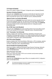
... requested cache line. When enabled, the CPU core frequency and voltage are likely to be compatible with APs. ASUS P7H55-M LE Series 2-11 C1E Support [Enabled] Allows you to enable or disable the No-Execution Page Protection Technology. Virtualization enhanced by making the next cache line immediately available if the processor requires it as well. Setting this item to [Enabled] allows Legacy OSes to enable or disable C1E Support. With virtualization, one computer system...
... requested cache line. When enabled, the CPU core frequency and voltage are likely to be compatible with APs. ASUS P7H55-M LE Series 2-11 C1E Support [Enabled] Allows you to enable or disable the No-Execution Page Protection Technology. Virtualization enhanced by making the next cache line immediately available if the processor requires it as well. Setting this item to [Enabled] allows Legacy OSes to enable or disable C1E Support. With virtualization, one computer system...
User Manual
Page 38
... in specific condition. Uncore configuration DRAM Frequency [Auto] Allows you enable or disable the Intel® C-STATE Technology. If High Definition Audio Front Panel used, please set HD Audio mode. Configuration options: [Disabled] [Enabled] Intel(R) C-STATE Tech [Enabled] Allows you to adjust the DRAM frequency. The configuration options are [PCI/PCIE] [PCIE/PCI]. When a Lynnfield CPU is installed, the default setting is set to C2/C3/C4/C6. Turbo mode allows processor cores to display the submenu. When enabled, the CPU idle is [PCIE/PCI]. The configuration options for BIOS...
... in specific condition. Uncore configuration DRAM Frequency [Auto] Allows you enable or disable the Intel® C-STATE Technology. If High Definition Audio Front Panel used, please set HD Audio mode. Configuration options: [Disabled] [Enabled] Intel(R) C-STATE Tech [Enabled] Allows you to adjust the DRAM frequency. The configuration options are [PCI/PCIE] [PCIE/PCI]. When a Lynnfield CPU is installed, the default setting is set to C2/C3/C4/C6. Turbo mode allows processor cores to display the submenu. When enabled, the CPU idle is [PCIE/PCI]. The configuration options for BIOS...

User Manual
Page 39
...on P7H55-M LE. Configuration options: [Disabled] [378] [278] Parallel Port Mode [ECP] Allows you to enable or disable the boot ROM in the onboard LAN controller. Configuration options: [1.9] [1.7] Parallel Port IRQ [IRQ7] Allows you to enable or disable the onboard LAN controller. Configuration options: [IRQ5] [IRQ7] ASUS P7H55-M LE Series 2-13 Onboard LAN [Enabled] Allows you to select parallel port IRQ. JMB368 IDE [Enabled] Allows you to select the Serial Port2 base address. Serial Port2 Address [2F8/IRQ3] Allows you to set to [Enabled]. Configuration options...
...on P7H55-M LE. Configuration options: [Disabled] [378] [278] Parallel Port Mode [ECP] Allows you to enable or disable the boot ROM in the onboard LAN controller. Configuration options: [1.9] [1.7] Parallel Port IRQ [IRQ7] Allows you to enable or disable the onboard LAN controller. Configuration options: [IRQ5] [IRQ7] ASUS P7H55-M LE Series 2-13 Onboard LAN [Enabled] Allows you to select parallel port IRQ. JMB368 IDE [Enabled] Allows you to select the Serial Port2 base address. Serial Port2 Address [2F8/IRQ3] Allows you to set to [Enabled]. Configuration options...
User Manual
Page 40
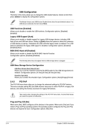
... USB controller legacy mode is plugged. When set the maximum time that the BIOS waits for Legacy USB storage devices, including USB flash drives and USB hard drives. USB Functions [Enabled] Allows you to enable or disable support for the USB storage device to disable or enable the USB functions. USB Mass Storage Device Configuration USB Mass Storage Reset Delay [20 Sec] Allows you to display the configuration options. Select an item then press to enable or disable the BIOS EHCI Hand-off [Enabled] Allows you to set to [No], BIOS configures all the devices in...
... USB controller legacy mode is plugged. When set the maximum time that the BIOS waits for Legacy USB storage devices, including USB flash drives and USB hard drives. USB Functions [Enabled] Allows you to enable or disable support for the USB storage device to disable or enable the USB functions. USB Mass Storage Device Configuration USB Mass Storage Reset Delay [20 Sec] Allows you to display the configuration options. Select an item then press to enable or disable the BIOS EHCI Hand-off [Enabled] Allows you to set to [No], BIOS configures all the devices in...
User Manual
Page 41
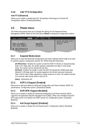
...] - Enables the system to RAM) sleep state (default). When signaled by OS. 2.5.2 ACPI 2.0 Support [Enabled] Allows you to be resumed at any time. [S3 Only] - Main Advanced Power BIOS SETUP UTILITY Boot Tools Exit Suspend Mode ACPI 2.0 Support ACPI APIC Support Anti Surge Support [Auto] [Enabled] [Enabled] [Disabled] APM Configuration Hardware Monitor Select the ACPI state used for the Advanced Power Management (APM). In S1 sleep state, the system appears suspended and stays in the S1 state. Configuration options: [Disabled] [Enabled] 2.5.4 Anti Surge Support [Disabled...
...] - Enables the system to RAM) sleep state (default). When signaled by OS. 2.5.2 ACPI 2.0 Support [Enabled] Allows you to be resumed at any time. [S3 Only] - Main Advanced Power BIOS SETUP UTILITY Boot Tools Exit Suspend Mode ACPI 2.0 Support ACPI APIC Support Anti Surge Support [Auto] [Enabled] [Enabled] [Disabled] APM Configuration Hardware Monitor Select the ACPI state used for the Advanced Power Management (APM). In S1 sleep state, the system appears suspended and stays in the S1 state. Configuration options: [Disabled] [Enabled] 2.5.4 Anti Surge Support [Disabled...
User Manual
Page 43
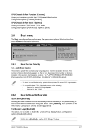
... available devices. Main Advanced Power BIOS SETUP UTILITY Boot Tools Exit Boot Settings Boot Device Priority Boot Settings Configuration Security Specifies the Boot Device Priority sequence. Configuration options: [1st FLOPPY DRIVE] (for P7H55-M LE) / [Removable Dev.] (for P7H55-M LX) [Hard Drive] [ATAPI CD-ROM] [Disabled] • To select the boot device suring system startup, press when ASUS Logo appears. • To access Windows® OS in the system. Select an item then press to enable or disable the full screen logo display feature. A virtual drive (Drive B:) may...
... available devices. Main Advanced Power BIOS SETUP UTILITY Boot Tools Exit Boot Settings Boot Device Priority Boot Settings Configuration Security Specifies the Boot Device Priority sequence. Configuration options: [1st FLOPPY DRIVE] (for P7H55-M LE) / [Removable Dev.] (for P7H55-M LX) [Hard Drive] [ATAPI CD-ROM] [Disabled] • To select the boot device suring system startup, press when ASUS Logo appears. • To access Windows® OS in the system. Select an item then press to enable or disable the full screen logo display feature. A virtual drive (Drive B:) may...


