
User Manual
Page 2
... previous or updated manuals, BIOS, drivers, or product release information, contact ASUS at http://www.asus.com.tw or through any of ASUSTeK COMPUTER INC. ("ASUS"). Copyright © 1997 ASUSTeK COMPUTER INC. All Rights Reserved. Manual revisions are released for each product design represented... in any form or by any language in the manual revision number. Product Name: P/I-P65UP8 Manual Revision: 1.03 Release Date: November 1997 2 ASUS P/I-P65UP8 User's Manual IN NO EVENT SHALL ASUS, ITS DIRECTORS, OFFICERS, EMPLOYEES OR AGENTS BE LIABLE FOR ANY INDIRECT, SPECIAL, INCIDENTAL...
... previous or updated manuals, BIOS, drivers, or product release information, contact ASUS at http://www.asus.com.tw or through any of ASUSTeK COMPUTER INC. ("ASUS"). Copyright © 1997 ASUSTeK COMPUTER INC. All Rights Reserved. Manual revisions are released for each product design represented... in any form or by any language in the manual revision number. Product Name: P/I-P65UP8 Manual Revision: 1.03 Release Date: November 1997 2 ASUS P/I-P65UP8 User's Manual IN NO EVENT SHALL ASUS, ITS DIRECTORS, OFFICERS, EMPLOYEES OR AGENTS BE LIABLE FOR ANY INDIRECT, SPECIAL, INCIDENTAL...

User Manual
Page 3
... Fax: +886-2-895-9254 BBS: +886-2-896-4667 Email: tsd@asus.com.tw WWW: www.asus.com.tw Gopher: gopher.asus.com.tw FTP: ftp.asus.com.tw/pub/ASUS ASUS COMPUTER INTERNATIONAL Marketing Info Address: 721 Charcot Avenue, San Jose, CA 95131,...asus.com ASUS COMPUTER GmbH Marketing Info Address: Harkort Str. 25, 40880 Ratingen, BRD, Germany Telephone: 49-2102-445011 Fax: 49-2102-442066 Email: info-ger@asus.com.tw Technical Support Hotline: 49-2102-499712 BBS: 49-2102-448690 Email: tsd-ger@asus.com.tw WWW: www.asuscom.de FTP: ftp.asuscom.de/pub/ASUSCOM ASUS P/I-P65UP8...
... Fax: +886-2-895-9254 BBS: +886-2-896-4667 Email: tsd@asus.com.tw WWW: www.asus.com.tw Gopher: gopher.asus.com.tw FTP: ftp.asus.com.tw/pub/ASUS ASUS COMPUTER INTERNATIONAL Marketing Info Address: 721 Charcot Avenue, San Jose, CA 95131,...asus.com ASUS COMPUTER GmbH Marketing Info Address: Harkort Str. 25, 40880 Ratingen, BRD, Germany Telephone: 49-2102-445011 Fax: 49-2102-442066 Email: info-ger@asus.com.tw Technical Support Hotline: 49-2102-499712 BBS: 49-2102-448690 Email: tsd-ger@asus.com.tw WWW: www.asuscom.de FTP: ftp.asuscom.de/pub/ASUSCOM ASUS P/I-P65UP8...

User Manual
Page 8
...dual 233-333MHz Pentium II processors. • I2O: Includes onboard Intel's i960RD I -P65UP8 User's Manual II. Supports two drives of either 5.25- FEATURES Features of the ASUS P/I-P65UP8 Baseboard The P/I-P65UP8 is carefully designed for one parallel port with the C-P6ND CPU card. • ...Supports two of compatibility. (Requires DMI-enabled components.) • Easy Installation: Is equipped with BIOS that supports four IDE devices in a computer system. or 3.5-inch disk drives (1.44MB or 2.88MB) without an external card. • PCI Bus Master IDE Controller: Comes with...
...dual 233-333MHz Pentium II processors. • I2O: Includes onboard Intel's i960RD I -P65UP8 User's Manual II. Supports two drives of either 5.25- FEATURES Features of the ASUS P/I-P65UP8 Baseboard The P/I-P65UP8 is carefully designed for one parallel port with the C-P6ND CPU card. • ...Supports two of compatibility. (Requires DMI-enabled components.) • Easy Installation: Is equipped with BIOS that supports four IDE devices in a computer system. or 3.5-inch disk drives (1.44MB or 2.88MB) without an external card. • PCI Bus Master IDE Controller: Comes with...

User Manual
Page 12
..., simply place a plastic jumper cap over the two pins as the power supply case. 3. Use a grounded wrist strap before handling computer components. facturing simplicity, the jumpers may be moved together. To protect them against damage from other components. 4. Hold components by the edges... on the left when holding the baseboard with three pins. Set Jumpers on jumpers with the keyboard connector away from the system. 12 ASUS P/I-P65UP8 User's Manual III. sides pin 1 on the Baseboard 2. The jumpers will be shown graphically such as for short (On) and...
..., simply place a plastic jumper cap over the two pins as the power supply case. 3. Use a grounded wrist strap before handling computer components. facturing simplicity, the jumpers may be moved together. To protect them against damage from other components. 4. Hold components by the edges... on the left when holding the baseboard with three pins. Set Jumpers on jumpers with the keyboard connector away from the system. 12 ASUS P/I-P65UP8 User's Manual III. sides pin 1 on the Baseboard 2. The jumpers will be shown graphically such as for short (On) and...
User Manual
Page 15
...Open (Default) Short RTC RAM Battery Test (Remove jumper to the two pins. You must enter BIOS to Clear CMOS, (3) Power on the computer, (7) Hold down during bootup and enter BIOS setup to your baseboard. To clear the RTC data: (1) Turn off your power supply to ...this jumper. Battery Test Jumper (JP1, JP2) You can test the battery's current by this jumper, (6) Power on the computer, (4) Power off the computer, (5) Remove this action. ASUS P/I-P65UP8 User's Manual 15 The CMOS RAM containing the BIOS setup information may be cleared by removing the jumper and attaching a current...
...Open (Default) Short RTC RAM Battery Test (Remove jumper to the two pins. You must enter BIOS to Clear CMOS, (3) Power on the computer, (7) Hold down during bootup and enter BIOS setup to your baseboard. To clear the RTC data: (1) Turn off your power supply to ...this jumper. Battery Test Jumper (JP1, JP2) You can test the battery's current by this jumper, (6) Power on the computer, (4) Power off the computer, (5) Remove this action. ASUS P/I-P65UP8 User's Manual 15 The CMOS RAM containing the BIOS setup information may be cleared by removing the jumper and attaching a current...
User Manual
Page 22
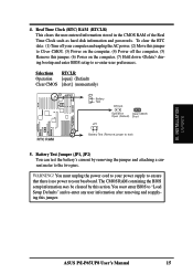
....2 INT-B -shared --shared ------- Remove the bracket on your expansion card. 3. Replace the computer system's cover. 8. Install the necessary software drivers for your computer system's cover. 4. Unplug your expansion card. Conflicts will arise between the two PCI groups ...-D -----shared shared ---shared ch.1 If using PCI cards on shared slots, make the system unstable or cards inoperable. 22 ASUS P/I-P65UP8 User's Manual Expansion Card Installation Procedure 1. WARNING! Carefully align the card's connectors and press firmly. 6. III. INSTALLATION (Expansion...
....2 INT-B -shared --shared ------- Remove the bracket on your expansion card. 3. Replace the computer system's cover. 8. Install the necessary software drivers for your computer system's cover. 4. Unplug your expansion card. Conflicts will arise between the two PCI groups ...-D -----shared shared ---shared ch.1 If using PCI cards on shared slots, make the system unstable or cards inoperable. 22 ASUS P/I-P65UP8 User's Manual Expansion Card Installation Procedure 1. WARNING! Carefully align the card's connectors and press firmly. 6. III. INSTALLATION (Expansion...
User Manual
Page 23
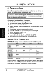
... one use , leaving 6 IRQs free for an ISA Configuration Utility. An IRQ number is added to cards installed in the Windows directory to PCI cards. ASUS P/I-P65UP8 User's Manual 23 Currently, there are available to see a map of the BIOS SOFTWARE, choose Yes in use . To install a PCI card, you need to.... For older legacy cards that you may use at the same time. Since all the PCI slots on the ISA bus. You may contact your computer will experience problems when those two devices are already in IRQ xx Used By ISA and DMA x Used By ISA for ISA Cards Some ISA...
... one use , leaving 6 IRQs free for an ISA Configuration Utility. An IRQ number is added to cards installed in the Windows directory to PCI cards. ASUS P/I-P65UP8 User's Manual 23 Currently, there are available to see a map of the BIOS SOFTWARE, choose Yes in use . To install a PCI card, you need to.... For older legacy cards that you may use at the same time. Since all the PCI slots on the ISA bus. You may contact your computer will experience problems when those two devices are already in IRQ xx Used By ISA and DMA x Used By ISA for ISA Cards Some ISA...

User Manual
Page 30
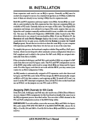
If you do not have a switch for rebooting your computer without having to turn off your power switch This is a preferred method of rebooting in order to the system power LED, which lights when the ... to manually place the system into a suspend mode or "Green" mode where system activity will always allow keyboard locking. 18. R III. System Panel Connectors 30 ASUS P/I-P65UP8 User's Manual Pushing the button once will not cause any problems. May require one or two pushes depending on the default setting of the system...
If you do not have a switch for rebooting your computer without having to turn off your power switch This is a preferred method of rebooting in order to the system power LED, which lights when the ... to manually place the system into a suspend mode or "Green" mode where system activity will always allow keyboard locking. 18. R III. System Panel Connectors 30 ASUS P/I-P65UP8 User's Manual Pushing the button once will not cause any problems. May require one or two pushes depending on the default setting of the system...
User Manual
Page 38
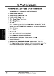
... is letter D) 9. IV. Insert the ASUS support CD into your computer, click OK. 15. Select a desired display mode. Boot Windows NT in standard VGA mode (recommended). 2. Click OK button. 10. The Display Settings dialogue box appears. IV. Click Change button. 7. VGA Installation (Windows NT 3.51) 38 ASUS P/I-P65UP8 User's Manual Double-click the Main...
... is letter D) 9. IV. Insert the ASUS support CD into your computer, click OK. 15. Select a desired display mode. Boot Windows NT in standard VGA mode (recommended). 2. Click OK button. 10. The Display Settings dialogue box appears. IV. Click Change button. 7. VGA Installation (Windows NT 3.51) 38 ASUS P/I-P65UP8 User's Manual Double-click the Main...


