Motherboard Installation Guide
Page 30
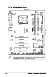
... Super I/O ESATA PARALLEL PORT FLOPPY DDR2 DIMM_B1 (64 bit,240-pin module) DDR2 DIMM_B2 (64 bit,240-pin module) ® P5W64 WS PRO DDR2 DIMM_A1 (64 bit,240-pin module) DDR2 DIMM_A2 (64 bit,240-pin module) LAN1_USB12 LAN2_USB34 EATXPWR EZ_PLUG PRI_IDE AUDIO CHA_FAN1 Intel®...Power PCIEX16_4 PCI1 SB_PWR TSB43AB22A Intel® ICH7R SATA4 SATA3 SATA2 SATA1 Marvell® 88E8001 8Mb PCI2 Marvell® 88SE614x TPM BIOS CLRTC CD COM1 USB78 USB56 IE1394_1 IE1394_2 EXT_SATA3 EXT_SATA2 EXT_SATA1 CHASSIS AAFP PANEL The Wireless LAN module and the USB port on...
... Super I/O ESATA PARALLEL PORT FLOPPY DDR2 DIMM_B1 (64 bit,240-pin module) DDR2 DIMM_B2 (64 bit,240-pin module) ® P5W64 WS PRO DDR2 DIMM_A1 (64 bit,240-pin module) DDR2 DIMM_A2 (64 bit,240-pin module) LAN1_USB12 LAN2_USB34 EATXPWR EZ_PLUG PRI_IDE AUDIO CHA_FAN1 Intel®...Power PCIEX16_4 PCI1 SB_PWR TSB43AB22A Intel® ICH7R SATA4 SATA3 SATA2 SATA1 Marvell® 88E8001 8Mb PCI2 Marvell® 88SE614x TPM BIOS CLRTC CD COM1 USB78 USB56 IE1394_1 IE1394_2 EXT_SATA3 EXT_SATA2 EXT_SATA1 CHASSIS AAFP PANEL The Wireless LAN module and the USB port on...
Motherboard Installation Guide
Page 53
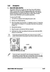
...down and reboot the system so the BIOS can clear the CMOS memory of date, time, and system setup parameters by erasing the CMOS RTC RAM data. Removing the cap will cause system boot failure! ® P5W64 WS PRO CLRTC 12 23 Normal (Default) P5W64 WS PRO Clear RTC RAM Clear RTC You do...cap from pins 1-2 (default) to clear the Real Time Clock (RTC) RAM in CMOS, which include system setup information such as system passwords. ASUS P5W64 WS Professional 2-27 Except when clearing the RTC RAM, never remove the cap on pins 2-3 for about 5~10 seconds, then move the cap back to ...
...down and reboot the system so the BIOS can clear the CMOS memory of date, time, and system setup parameters by erasing the CMOS RTC RAM data. Removing the cap will cause system boot failure! ® P5W64 WS PRO CLRTC 12 23 Normal (Default) P5W64 WS PRO Clear RTC RAM Clear RTC You do...cap from pins 1-2 (default) to clear the Real Time Clock (RTC) RAM in CMOS, which include system setup information such as system passwords. ASUS P5W64 WS Professional 2-27 Except when clearing the RTC RAM, never remove the cap on pins 2-3 for about 5~10 seconds, then move the cap back to ...
Motherboard Installation Guide
Page 58
...® ICH7R RAID controller. • These connectors are for Serial ATA signal cables for each RAID 0 or RAID 1 set the C o n f i g u r e S A T A A s item in the BIOS to these connectors, set . ® P5W64 WS PRO GND SATA_TXP2 SATA_TXN2 GND SATA_RXN2 SATA_RXP2 GND GND SATA_TXP3 SATA_TXN3 GND SATA_RXN3 SATA_RXP3 GND GND SATA_RXP0 SATA_RXN0 GND SATA_TXN0 SATA_TXP0 GND SATA4...
...® ICH7R RAID controller. • These connectors are for Serial ATA signal cables for each RAID 0 or RAID 1 set the C o n f i g u r e S A T A A s item in the BIOS to these connectors, set . ® P5W64 WS PRO GND SATA_TXP2 SATA_TXN2 GND SATA_RXN2 SATA_RXP2 GND GND SATA_TXP3 SATA_TXN3 GND SATA_RXN3 SATA_RXP3 GND GND SATA_RXP0 SATA_RXN0 GND SATA_TXN0 SATA_TXP0 GND SATA4...
Motherboard Installation Guide
Page 59
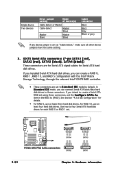
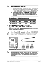
...connectors in the BIOS to [Enabled] to use the connectors to build a RAID set using Serial ATA hard disk drives. See section "4.4.6 Onboard Devices Configuration" for Serial ATA signal cables. otherwise, you are for details. ® P5W64 WS PRO GND RSATA_TX_0_DP RSATA_TX_0_DN ... GND EXT_SATA3 EXT_SATA2 EXT_SATA1 P5W64 WS PRO SATA 3 Gbps connector Before creating a RAID set . Serial ATA hard disk drive connection Connector Color Setting Use SATA1/SATA2 Red Master Boot disk SATA3/SATA4 Black Slave Data disk 4 . ASUS P5W64 WS Professional 2-33 Refer to the...
...connectors in the BIOS to [Enabled] to use the connectors to build a RAID set using Serial ATA hard disk drives. See section "4.4.6 Onboard Devices Configuration" for Serial ATA signal cables. otherwise, you are for details. ® P5W64 WS PRO GND RSATA_TX_0_DP RSATA_TX_0_DN ... GND EXT_SATA3 EXT_SATA2 EXT_SATA1 P5W64 WS PRO SATA 3 Gbps connector Before creating a RAID set . Serial ATA hard disk drive connection Connector Color Setting Use SATA1/SATA2 Red Master Boot disk SATA3/SATA4 Black Slave Data disk 4 . ASUS P5W64 WS Professional 2-33 Refer to the...
Motherboard Installation Guide
Page 60
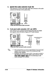
...connector is set the F r o n t P a n e l S u p p o r t T y p e item in the BIOS Setup to AC'97. HD-Audio-compliant pin definition Legacy AC'97-compliant pin definition AAFP P5W64 WS PRO Front panel audio connector • We recommend that connects to the audio connector at the back of... module to this connector to avail of the optical drive. ® P5W64 WS PRO Right Audio Channel Ground Ground Left Audio Channel AGND PRESENCE# SENSE1_RETUR SENSE2_RETUR ® P5W64 WS PRO AGND NC NC NC CD (black) P5W64 WS PRO Internal audio connector 6 . Optical drive audio connector (4-pin CD) This...
...connector is set the F r o n t P a n e l S u p p o r t T y p e item in the BIOS Setup to AC'97. HD-Audio-compliant pin definition Legacy AC'97-compliant pin definition AAFP P5W64 WS PRO Front panel audio connector • We recommend that connects to the audio connector at the back of... module to this connector to avail of the optical drive. ® P5W64 WS PRO Right Audio Channel Ground Ground Left Audio Channel AGND PRESENCE# SENSE1_RETUR SENSE2_RETUR ® P5W64 WS PRO AGND NC NC NC CD (black) P5W64 WS PRO Internal audio connector 6 . Optical drive audio connector (4-pin CD) This...

Motherboard Installation Guide
Page 67
PLED+ PLED+5V Ground Ground Speaker ® P5W64 WS PRO IDE_LED+ IDE_LED- The speaker allows you turn on the system power, and blinks when the system is in sleep or soft-off mode depending on ... button/soft-off the system power. Pressing the power button turns the system on the BIOS settings. ASUS P5W64 WS Professional 2-41 Connect the chassis power LED cable to this connector. Connect the HDD Activity LED cable to this connector. P5W64 WS PRO System panel connector • System power LED This 3-pin connector is for system reboot without...
PLED+ PLED+5V Ground Ground Speaker ® P5W64 WS PRO IDE_LED+ IDE_LED- The speaker allows you turn on the system power, and blinks when the system is in sleep or soft-off mode depending on ... button/soft-off the system power. Pressing the power button turns the system on the BIOS settings. ASUS P5W64 WS Professional 2-41 Connect the chassis power LED cable to this connector. Connect the HDD Activity LED cable to this connector. P5W64 WS PRO System panel connector • System power LED This 3-pin connector is for system reboot without...

Motherboard Installation Guide
Page 79
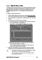
... and single partition only. • Do not shutdown or reset the system while updating the BIOS to prevent system boot failure! ASUS P5W64 WS Professional 4-5 ASUSTek EZ Flash 2 BIOS ROM Utility V3.00 FLASH TYPE: Winbond W39V080A 8Mb LPC Current ROM BOARD: P5W64-WS Pro VER: 0204 DATE: 07/04/2006 Update ROM BOARD: Unknown VER: Unknown DATE: Unknown...
... and single partition only. • Do not shutdown or reset the system while updating the BIOS to prevent system boot failure! ASUS P5W64 WS Professional 4-5 ASUSTek EZ Flash 2 BIOS ROM Utility V3.00 FLASH TYPE: Winbond W39V080A 8Mb LPC Current ROM BOARD: P5W64-WS Pro VER: 0204 DATE: 07/04/2006 Update ROM BOARD: Unknown VER: Unknown DATE: Unknown...
Motherboard Installation Guide
Page 118
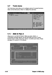
...right arrow key to select between [Yes] or [No], then press to display the sub-menu. ASUSTek EZ Flash 2 BIOS ROM Utility V3.00 FLASH TYPE: SST 49LF008 FWH Current ROM BOARD: P5W64-WS PRO VER: 0116 DATE: 08/01/2006 Update ROM BOARD: Unknown VER: Unknown DATE: Unknown PATH: C:\ A: C: BWiInN98SE...Sub Screen F1 General Help F10 Save and Exit ESC Exit v02.58 (C)Copyright 1985-2005, American Megatrends, Inc. 4.7.1 ASUS EZ Flash 2 Allows you to run the utility to run ASUS EZ Flash 2. 4.7 Tools menu The Tools menu items allow you press , a confirmation message appears. Select an item then...
...right arrow key to select between [Yes] or [No], then press to display the sub-menu. ASUSTek EZ Flash 2 BIOS ROM Utility V3.00 FLASH TYPE: SST 49LF008 FWH Current ROM BOARD: P5W64-WS PRO VER: 0116 DATE: 08/01/2006 Update ROM BOARD: Unknown VER: Unknown DATE: Unknown PATH: C:\ A: C: BWiInN98SE...Sub Screen F1 General Help F10 Save and Exit ESC Exit v02.58 (C)Copyright 1985-2005, American Megatrends, Inc. 4.7.1 ASUS EZ Flash 2 Allows you to run the utility to run ASUS EZ Flash 2. 4.7 Tools menu The Tools menu items allow you press , a confirmation message appears. Select an item then...
Motherboard Installation Guide
Page 119
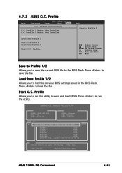
.../Home/End] Move ASUS P5W64 WS Professional 4-45 Profile Utility V1.00 Current CMOS BOARD: P5W64-WS PRO VER: 0116 DATE: 08/01/06 Update CMOS BOARD: Unknown VER: Unknown DATE: Unknown PATH: C:\ A: CMOS bWaIcNk9u8pSEis done! Press to load the file. Load from Profile 2 Start O.C. Press any key to the BIOS Flash. Profile Main Advanced BIOS SETUP UTILITY Power...
.../Home/End] Move ASUS P5W64 WS Professional 4-45 Profile Utility V1.00 Current CMOS BOARD: P5W64-WS PRO VER: 0116 DATE: 08/01/06 Update CMOS BOARD: Unknown VER: Unknown DATE: Unknown PATH: C:\ A: CMOS bWaIcNk9u8pSEis done! Press to load the file. Load from Profile 2 Start O.C. Press any key to the BIOS Flash. Profile Main Advanced BIOS SETUP UTILITY Power...

Motherboard Installation Guide
Page 163
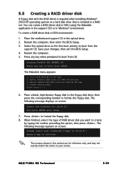
...174; 2000/XP operating system on a hard disk drive that is included in DOS environment: 1. Restart the computer, then enter the BIOS Setup. 3. Select the optical drive as the first boot priority to boot from the support CD. Press to boot from CD. Insert... Restart the computer. 5. The Makedisk menu appears. 1) Intel ICH7R RAID/AHCI Driver Page 2) Marvell 88SE6141 SATA Driver for P5WDG2 WS PRO Page 3) Marvell 88SE6145 SATA RAID Driver for P5W64 WS PRO Page 4) FreeDOS command prompt Please choose 1 ~ 4 6. The following message appears on screen. ASUS P5W64 WS Professional 5-39
...174; 2000/XP operating system on a hard disk drive that is included in DOS environment: 1. Restart the computer, then enter the BIOS Setup. 3. Select the optical drive as the first boot priority to boot from the support CD. Press to boot from CD. Insert... Restart the computer. 5. The Makedisk menu appears. 1) Intel ICH7R RAID/AHCI Driver Page 2) Marvell 88SE6141 SATA Driver for P5WDG2 WS PRO Page 3) Marvell 88SE6145 SATA RAID Driver for P5W64 WS PRO Page 4) FreeDOS command prompt Please choose 1 ~ 4 6. The following message appears on screen. ASUS P5W64 WS Professional 5-39

P5W64 WS Professional English Edition User's Manual
Page 30
... Super I/O ESATA PARALLEL PORT FLOPPY DDR2 DIMM_B1 (64 bit,240-pin module) DDR2 DIMM_B2 (64 bit,240-pin module) ® P5W64 WS PRO DDR2 DIMM_A1 (64 bit,240-pin module) DDR2 DIMM_A2 (64 bit,240-pin module) LAN1_USB12 LAN2_USB34 EATXPWR EZ_PLUG PRI_IDE AUDIO CHA_FAN1 Intel®...Power PCIEX16_4 PCI1 SB_PWR TSB43AB22A Intel® ICH7R SATA4 SATA3 SATA2 SATA1 Marvell® 88E8001 8Mb PCI2 Marvell® 88SE614x TPM BIOS CLRTC CD COM1 USB78 USB56 IE1394_1 IE1394_2 EXT_SATA3 EXT_SATA2 EXT_SATA1 CHASSIS AAFP PANEL The Wireless LAN module and the USB port on...
... Super I/O ESATA PARALLEL PORT FLOPPY DDR2 DIMM_B1 (64 bit,240-pin module) DDR2 DIMM_B2 (64 bit,240-pin module) ® P5W64 WS PRO DDR2 DIMM_A1 (64 bit,240-pin module) DDR2 DIMM_A2 (64 bit,240-pin module) LAN1_USB12 LAN2_USB34 EATXPWR EZ_PLUG PRI_IDE AUDIO CHA_FAN1 Intel®...Power PCIEX16_4 PCI1 SB_PWR TSB43AB22A Intel® ICH7R SATA4 SATA3 SATA2 SATA1 Marvell® 88E8001 8Mb PCI2 Marvell® 88SE614x TPM BIOS CLRTC CD COM1 USB78 USB56 IE1394_1 IE1394_2 EXT_SATA3 EXT_SATA2 EXT_SATA1 CHASSIS AAFP PANEL The Wireless LAN module and the USB port on...

P5W64 WS Professional English Edition User's Manual
Page 53
... RAM data in CMOS. Keep the cap on CLRTC jumper default position. Shut down the key during the boot process and enter BIOS setup to re-enter data. ASUS P5W64 WS Professional 2-27 Reinstall the battery. 5. Except when clearing the RTC RAM, never remove the cap on pins 2-3 for about 5~10 ... down and reboot the system so the BIOS can clear the CMOS memory of date, time, and system setup parameters by erasing the CMOS RTC RAM data. Removing the cap will cause system boot failure! ® P5W64 WS PRO CLRTC 12 23 Normal (Default) P5W64 WS PRO Clear RTC RAM Clear RTC You do ...
... RAM data in CMOS. Keep the cap on CLRTC jumper default position. Shut down the key during the boot process and enter BIOS setup to re-enter data. ASUS P5W64 WS Professional 2-27 Reinstall the battery. 5. Except when clearing the RTC RAM, never remove the cap on pins 2-3 for about 5~10 ... down and reboot the system so the BIOS can clear the CMOS memory of date, time, and system setup parameters by erasing the CMOS RTC RAM data. Removing the cap will cause system boot failure! ® P5W64 WS PRO CLRTC 12 23 Normal (Default) P5W64 WS PRO Clear RTC RAM Clear RTC You do ...

P5W64 WS Professional English Edition User's Manual
Page 58
... [black]) These connectors are set to [RAID]. If you intend to create a Serial ATA RAID set the C o n f i g u r e S A T A A s item in the BIOS to S t a n d a r d I D E mode, you can connect Serial ATA boot/data hard disk drives to four Serial ATA hard disk drives for details. • For RAID 5, use... Slave Master Slave Cable connector Black Black Gray Black or gray If any device jumper is set . ® P5W64 WS PRO GND SATA_TXP2 SATA_TXN2 GND SATA_RXN2 SATA_RXP2 GND GND SATA_TXP3 SATA_TXN3 GND SATA_RXN3 SATA_RXP3 GND GND SATA_RXP0 SATA_RXN0 GND SATA_TXN0 SATA_TXP0 GND SATA4...
... [black]) These connectors are set to [RAID]. If you intend to create a Serial ATA RAID set the C o n f i g u r e S A T A A s item in the BIOS to S t a n d a r d I D E mode, you can connect Serial ATA boot/data hard disk drives to four Serial ATA hard disk drives for details. • For RAID 5, use... Slave Master Slave Cable connector Black Black Gray Black or gray If any device jumper is set . ® P5W64 WS PRO GND SATA_TXP2 SATA_TXN2 GND SATA_RXN2 SATA_RXP2 GND GND SATA_TXP3 SATA_TXN3 GND SATA_RXN3 SATA_RXP3 GND GND SATA_RXP0 SATA_RXN0 GND SATA_TXN0 SATA_TXP0 GND SATA4...

P5W64 WS Professional English Edition User's Manual
Page 59
...These connectors are using Windows® 2000/XP/Server 2003 or later version. • When using the connectors in the BIOS to [Enabled] to use the connectors to the table below for the recommended SATA hard disk drive connections. Serial ATA ... GND RSATA_RX_2_DN RSATA_RX_2_DP GND EXT_SATA3 EXT_SATA2 EXT_SATA1 P5W64 WS PRO SATA 3 Gbps connector Before creating a RAID set . See section "4.4.6 Onboard Devices Configuration" for Serial ATA signal cables. These connectors support Serial ATA hard disk drives. ASUS P5W64 WS Professional 2-33 Important notes on Serial ATA &#...
...These connectors are using Windows® 2000/XP/Server 2003 or later version. • When using the connectors in the BIOS to [Enabled] to use the connectors to the table below for the recommended SATA hard disk drive connections. Serial ATA ... GND RSATA_RX_2_DN RSATA_RX_2_DP GND EXT_SATA3 EXT_SATA2 EXT_SATA1 P5W64 WS PRO SATA 3 Gbps connector Before creating a RAID set . See section "4.4.6 Onboard Devices Configuration" for Serial ATA signal cables. These connectors support Serial ATA hard disk drives. ASUS P5W64 WS Professional 2-33 Important notes on Serial ATA &#...

P5W64 WS Professional English Edition User's Manual
Page 60
...S u p p o r t T y p e item in the BIOS Setup to [HD Audio]. MIC_L MIC_R Line out_R NC Line out_L PORT1 L PORT1 R PORT2 R SENSE_SEND PORT2 L 2-34 Chapter 2: Hardware information HD-Audio-compliant pin definition Legacy AC'97-compliant pin definition AAFP P5W64 WS PRO Front panel audio connector • We recommend that you..., set to avail of the optical drive. ® P5W64 WS PRO Right Audio Channel Ground Ground Left Audio Channel AGND PRESENCE# SENSE1_RETUR SENSE2_RETUR ® P5W64 WS PRO AGND NC NC NC CD (black) P5W64 WS PRO Internal audio connector 6 . If you connect a high-...
...S u p p o r t T y p e item in the BIOS Setup to [HD Audio]. MIC_L MIC_R Line out_R NC Line out_L PORT1 L PORT1 R PORT2 R SENSE_SEND PORT2 L 2-34 Chapter 2: Hardware information HD-Audio-compliant pin definition Legacy AC'97-compliant pin definition AAFP P5W64 WS PRO Front panel audio connector • We recommend that you..., set to avail of the optical drive. ® P5W64 WS PRO Right Audio Channel Ground Ground Left Audio Channel AGND PRESENCE# SENSE1_RETUR SENSE2_RETUR ® P5W64 WS PRO AGND NC NC NC CD (black) P5W64 WS PRO Internal audio connector 6 . If you connect a high-...

P5W64 WS Professional English Edition User's Manual
Page 67
... power button/soft-off button This connector is for the chassis-mounted reset button for system reboot without turning off mode depending on the BIOS settings. Pressing the power switch for more than four seconds while the system is ON turns the system OFF. • Reset button ...the system is in sleep or soft-off the system power. PWR Ground Reset Ground 14. P5W64 WS PRO System panel connector • System power LED This 3-pin connector is for the system power button. ASUS P5W64 WS Professional 2-41 Connect the chassis power LED cable to the HDD. • System warning speaker This...
... power button/soft-off button This connector is for the chassis-mounted reset button for system reboot without turning off mode depending on the BIOS settings. Pressing the power switch for more than four seconds while the system is ON turns the system OFF. • Reset button ...the system is in sleep or soft-off the system power. PWR Ground Reset Ground 14. P5W64 WS PRO System panel connector • System power LED This 3-pin connector is for the system power button. ASUS P5W64 WS Professional 2-41 Connect the chassis power LED cable to the HDD. • System warning speaker This...
P5W64 WS Professional English Edition User's Manual
Page 79
... rename the same to a floppy disk or a USB flash disk, then restart the system. 3. Save the BIOS file to W 6 4 W S P R O . ASUS P5W64 WS Professional 4-5 ASUSTek EZ Flash 2 BIOS ROM Utility V3.00 FLASH TYPE: Winbond W39V080A 8Mb LPC Current ROM BOARD: P5W64-WS Pro VER: 0204 DATE: 07/04/2006 Update ROM BOARD: Unknown VER: Unknown DATE: Unknown PATH: A:\ A: Note...
... rename the same to a floppy disk or a USB flash disk, then restart the system. 3. Save the BIOS file to W 6 4 W S P R O . ASUS P5W64 WS Professional 4-5 ASUSTek EZ Flash 2 BIOS ROM Utility V3.00 FLASH TYPE: Winbond W39V080A 8Mb LPC Current ROM BOARD: P5W64-WS Pro VER: 0204 DATE: 07/04/2006 Update ROM BOARD: Unknown VER: Unknown DATE: Unknown PATH: A:\ A: Note...

P5W64 WS Professional English Edition User's Manual
Page 118
...Please see page 4-5, section 4.1.3 for special functions. Main Advanced BIOS SETUP UTILITY Power Boot Tools EZ Flash 2 ASUS O.C. 4.7 Tools menu The Tools menu items allow you to confirm your choice. Profile Exit Press ENTER to run ASUS EZ Flash 2. Use the left/right arrow key to select between... doesn't support: 1. When you to run the utility to display the sub-menu. ASUSTek EZ Flash 2 BIOS ROM Utility V3.00 FLASH TYPE: SST 49LF008 FWH Current ROM BOARD: P5W64-WS PRO VER: 0116 DATE: 08/01/2006 Update ROM BOARD: Unknown VER: Unknown DATE: Unknown PATH: C:\ A:...
...Please see page 4-5, section 4.1.3 for special functions. Main Advanced BIOS SETUP UTILITY Power Boot Tools EZ Flash 2 ASUS O.C. 4.7 Tools menu The Tools menu items allow you to confirm your choice. Profile Exit Press ENTER to run ASUS EZ Flash 2. Use the left/right arrow key to select between... doesn't support: 1. When you to run the utility to display the sub-menu. ASUSTek EZ Flash 2 BIOS ROM Utility V3.00 FLASH TYPE: SST 49LF008 FWH Current ROM BOARD: P5W64-WS PRO VER: 0116 DATE: 08/01/2006 Update ROM BOARD: Unknown VER: Unknown DATE: Unknown PATH: C:\ A:...

P5W64 WS Professional English Edition User's Manual
Page 119
...and load CMOS. Profile Allows you to save the current BIOS file to load the previous BIOS settings saved in the BIOS Flash. Press to load the file. ASUSTek O.C. Profile Utility V1.00 Current CMOS BOARD: P5W64-WS PRO VER: 0116 DATE: 08/01/06 Update CMOS BOARD: ... [ESC] Exit [Tab] Switch [Up/Down/Home/End] Move ASUS P5W64 WS Professional 4-45 Profile 2 Status: Not Installed Save to Profile 1 Load from Profile 1 Save to Profile 2 Load from Profile 1/2 Allows you to the BIOS Flash. Start O.C. 4.7.2 ASUS O.C. Press any key to save the file. Profile Exit Save to...
...and load CMOS. Profile Allows you to save the current BIOS file to load the previous BIOS settings saved in the BIOS Flash. Press to load the file. ASUSTek O.C. Profile Utility V1.00 Current CMOS BOARD: P5W64-WS PRO VER: 0116 DATE: 08/01/06 Update CMOS BOARD: ... [ESC] Exit [Tab] Switch [Up/Down/Home/End] Move ASUS P5W64 WS Professional 4-45 Profile 2 Status: Not Installed Save to Profile 1 Load from Profile 1 Save to Profile 2 Load from Profile 1/2 Allows you to the BIOS Flash. Start O.C. 4.7.2 ASUS O.C. Press any key to save the file. Profile Exit Save to...
P5W64 WS Professional English Edition User's Manual
Page 163
...CD in DOS environment: 1. The Makedisk menu appears. 1) Intel ICH7R RAID/AHCI Driver Page 2) Marvell 88SE6141 SATA Driver for P5WDG2 WS PRO Page 3) Marvell 88SE6145 SATA RAID Driver for drive B:\ and press ENTER when ready... 7. The following message appears on your changes, then exit...the BIOS Setup. 3. Press any key when prompted to boot from the support CD. Save your screen. Press any key to boot from CD. The following message displays on a hard disk drive that is required when installing Windows® 2000/XP operating system on screen. ASUS P5W64 WS Professional ...
...CD in DOS environment: 1. The Makedisk menu appears. 1) Intel ICH7R RAID/AHCI Driver Page 2) Marvell 88SE6141 SATA Driver for P5WDG2 WS PRO Page 3) Marvell 88SE6145 SATA RAID Driver for drive B:\ and press ENTER when ready... 7. The following message appears on your changes, then exit...the BIOS Setup. 3. Press any key when prompted to boot from the support CD. Save your screen. Press any key to boot from CD. The following message displays on a hard disk drive that is required when installing Windows® 2000/XP operating system on screen. ASUS P5W64 WS Professional ...


